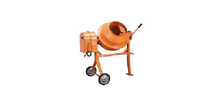
MACHINERY 3-1/2 Cubic Ft. Cement Mixer

Save This Manual Keep this manual for the safety warnings and precautions, assembly, operating, inspection, maintenance and cleaning procedures. Write the product’s serial number in the back of the manual near the assembly diagram (or month and year of purchase if product has no number). Keep this manual and the receipt in a safe and dry place for future reference.
Visit our website at: http://www.harborfreight.com
Email our technical support at: [email protected]
When unpacking, make sure that the product is intact and undamaged. If any parts are missing or broken, please call 1-888-866-5797 as soon as possible.
Copyright© 2009 by Harbor Freight Tools®. All rights reserved.
No portion of this manual or any artwork contained herein may be reproduced in any shape or form without the express written consent of Harbor Freight Tools. Diagrams within this manual may not be drawn proportionally. Due to continuing improvements, actual product may differ slightly from the product described herein. Tools required for assembly and service may not be included.
WARNING
Read this material before using this product. Failure to do so can result in serious injury. SAVE THIS MANUAL.
NOTICE
FOR CEMENT AND MORTAR ONLY. Do not use with Epoxy 2-part resin mix.
INSTRUCTIONS PERTAINING TO RISK OF FIRE, ELECTRIC SHOCK, OR INJURY TO PERSONS
IMPORTANT SAFETY INSTRUCTIONS
WARNING – When using electric appliances, basic precautions should always be followed, including the following:
- Read all the instructions before using the appliance.
- To reduce the risk of injury, close supervision is necessary when an appliance is used near children.
- Do not contact moving parts.
- Only use attachments recommended or sold by the manufacturer.
- To disconnect, turn all controls to the off (“O”) position, then remove plug from outlet.
- Do not unplug by pulling on cord. To unplug, grasp the plug, not the cord.
- Unplug from outlet when not in use and before servicing or cleaning.
- Do not operate any appliance with a damaged cord or plug, or after the appliance malfunctions or is dropped or damaged in any manner. Return appliance to the nearest authorized service facility for examination, repair, or electrical or mechanical adjustment.
- Connect to a properly grounded outlet only. See Grounding Instructions.
GROUNDING INSTRUCTIONS
This appliance must be grounded. In the event of malfunction or breakdown, grounding provides a path of least resistance for electric current to reduce the risk of electric shock. This appliance is equipped with a cord having an equipment-grounding conductor and a grounding plug. The plug must be plugged into an appropriate outlet that is properly installed and grounded in accordance with all local codes and ordinances.
WARNING
DANGER – Improper connection of the equipment-grounding conductor can result in a risk of electric shock. Check with a qualified electrician or serviceman if the grounding instructions are not completely understood, or if in doubt as to whether the appliance is properly grounded. Do not modify the plug provided with the appliance – if it will not fit the outlet, have a proper outlet installed by a qualified electrician.
NOTICE
FOR CEMENT AND MORTAR ONLY. Do not use with Epoxy 2-part resin mix.
This appliance is for use on a nominal 120 V circuit, and has a grounding plug that looks like the plug illustrated in Figure A.  A temporary adaptor, which looks like the adaptor illustrated in Figures B and C, may be used to connect this plug to a 2-pole receptacle as shown in Figure B if a properly grounded outlet is not available.
  The temporary adaptor should be used only until a properly grounded outlet can be installed by a qualified electrician. The green colored rigid ear, lug, and the like, extending from the adaptor must be connected to
a permanent ground such as a properly grounded outlet box cover. Whenever the adaptor is used, it must be held in place by the metal screw, as shown in Figure C.  Figure C: Grounding Adapter Connection
The adapter should not be used if a three-slot grounded receptacle is available. A qualified electrician should be consulted if there is any doubt as to whether an outlet box is properly grounded.
Extension Cords
- Extension cords (or a longer detachable power-supply cords) are available and may be used if care is exercised in their use.
- If an extension cord (or a longer detachable power-supply cord) is used:
a. The marked electrical rating of the detachable power-supply cord or extension cord should be at least as great as the electrical rating of the appliance,
b. If the appliance is of the grounded type, the extension cord should be a grounding type 3-wire cord, and
c. The longer extension cord (or a longer detachable power-supply cord) should be arranged so that it will not drape over the countertop or tabletop where it can be tripped over, snagged, or pulled on unintentionally (especially by children). - An outdoor-use extension cord should be used with an outdoor-use appliance. An outdoor-use extension cord is marked with suffix letter “W” and with a tag stating “Suitable for Use with Outdoor Appliances.”
- The connection to an extension cord should be kept dry and off the ground.
- Store appliance indoors when not in use. Keep out of reach of children.
- Do not clean this appliance with a water spray or the like.
- Grounded tools require a three wire extension cord. Double Insulated tools can use either a two or three wire extension cord.
- As the distance from the supply outlet increases, you must use a heavier gauge extension cord. Using extension cords with inadequately sized wire causes a serious drop in voltage, resulting in loss of power and possible tool damage. (See Table A.)
- The smaller the gauge number of the wire, the greater the capacity of the cord. For example, a 14 gauge cord can carry a higher current than a 16 gauge cord.(See Table A.)
- When using more than one extension cord to make up the total length, make sure each cord contains at least the minimum wire size required. (See Table A.)
- If you are using one extension cord for more than one tool, add the nameplate amperes and use the sum to determine the required minimum cord size. (See Table A.)
- Make sure the extension cord is properly wired and in good electrical condition. Always replace a damaged extension cord or have it repaired by a qualified electrician before using it.
- Protect the extension cords from sharp objects, excessive heat, and damp or wet areas.
| TABLE A: RECOMMENDED MINIMUM WIRE GAUGE FOR EXTENSION CORDS (120/240 VOLT) | |||||
| NAMEPLATE AMPERES (at full load) | EXTENSION CORD LENGTH | ||||
| 25´ | 50´ | 75´ | 100´ | 150´ | |
| 0 – 2.0 | 18 | 18 | 18 | 18 | 16 |
| 2.1 – 3.4 | 18 | 18 | 18 | 16 | 14 |
| 3.5 – 5.0 | 18 | 18 | 16 | 14 | 12 |
| 5.1 – 7.0 | 18 | 16 | 14 | 12 | 12 |
| 7.1 – 12.0 | 18 | 14 | 12 | 10 | – |
| 12.1 – 16.0 | 14 | 12 | 10 | – | – |
| 16.1 – 20.0 | 12 | 10 | – | – | – |
| Based on limiting the line voltage drop to five volts at 150% of the rated amperes. | |||||
Connecting Cords
To reduce the risk of the cords pulling apart during operation, do one of the following:
a. Make a knot as shown below then connect the cords: b Or, use a plug-receptacle retaining strap or connector designed to hold extension cords to appliance cords.
Mixer Safety Warnings
- FOR CEMENT AND MORTAR ONLY. DO NOT USE WITH EPOXY 2-PART RESIN MIX.
- DO NOT INSERT SHOVEL OR HANDS INTO MIXER WHILE PLUGGED IN. RISK OF SERIOUS INJURY OR DEATH FROM ENTANGLEMENT.
- Do not attempt to move the Cement Mixer when it is full and/or in operation. It is unsafe to move the mixer while in this condition, and severe injury to personnel could occur.
- Assemble only according to these instructions. Improper assembly can create hazards.
- Wear ANSI-approved safety goggles and heavy-duty work gloves during assembly.
- Keep assembly area clean and well lit.
- Keep bystanders out of the area during assembly.
- Do not assemble when tired or when under the influence of alcohol, drugs or medication.
- This product is not a toy. Do not allow children to play with this item.
- Use as intended only.
- Inspect before every use; do not use if parts are loose or damaged.
- Do not overload mixer.
- Keep safe clearance around mixer. Keep all persons (except operator) at least six feet from mixer during operation.
- Don’t use in dangerous environment. Don’t use power tools in damp or wet locations, or expose them to rain. Keep work area well lighted.
- Make workshop kid proof with padlocks, master switches, or by removing starter keys.
- Wear proper apparel. Do not wear loose clothing, gloves, neckties, rings, bracelets, or other jewelry which may get caught in moving parts. Nonslip footwear is recommended. Wear protective hair covering to contain long hair.
- Never leave tool running unattended. Turn power off. Don’t leave tool until it comes to a complete stop.
- Disconnect tools before servicing.
- When servicing use only identical replacement parts.
- Only use safety equipment that has been approved by an appropriate standards agency. Unapproved safety equipment may not provide adequate protection. Eye protection must be ANSI-approved and breathing protection must be NIOSH-approved for the specific hazards in the work area.
- Maintain labels and nameplates on
the tool. These carry important safety information. If unreadable or missing, contact Harbor Freight Tools for a replacement. - Avoid unintentional starting. Prepare to begin work before turning on the tool.
- People with pacemakers should consult their physician(s) before use. Electromagnetic fields in close proximity to heart pacemaker could cause pacemaker interference or pacemaker failure.
- The warnings, precautions, and instructions discussed in this instruction manual cannot cover all possible conditions and situations that may occur. It must be understood by the operator that common sense and caution are factors which cannot be built into this product, but must be supplied by the operator.
SPECIFICATIONS
| Electrical Input | 120 VAC / 60 Hz / 3.5A |
| Motor No Load Speed | 1950 RPM |
| Drum Speed | 36 RPM |
| Drum Capacity | 3-1/2″ Cubic Feet |
| Drum Opening | 15″ |
INSTRUCTIONS FOR PUTTING INTO USE
Read the ENTIRE IMPORTANT SAFETY INFORMATION section at the beginning of this manual including all text under subheadings therein before set up or use of this product.
WARNING TO PREVENT SERIOUS INJURY FROM ACCIDENTAL OPERATION: Turn the Power Switch of the tool to its “OFF” position and unplug the tool from its electrical outlet before assembling or making any adjustments to the tool.
Note: For additional information regarding the parts listed in the following pages, refer to the Assembly Diagram near the end of this manual.
Assembly/Mounting
- Place the Stand (27) into the Triangular Bracket (29) so that bolt holes line up.
See Figure D. Note: Set Stand on its side for easier assembly.
- Fasten together using Hex Bolts (61), Flat Washer (37) and Hex Flange Nut (34). Tighten with a wrench (not included) until secure.
- Insert Support Bracket (26) onto Stand so that bolt holes line up. See Figure E.

- Fasten together using Hex Bolts (61), Flat Washer (37) and Hex Flange Nut (34). Tighten with a wrench until secure.
- Place Stand upright.
- To attach Wheels (65) to Wheel Bracket, slide Flat Washer (64), Wheels and second Flat Washer onto Bracket axle. Then Insert Cotter Pins (63) into the Bracket’s axle holes and split the ends. See Figure F.

- With assistance, set the Lower Drum (3) with attached Arm (22) into Stand assembly. See Figure G.

- Fasten together using Hex Bolts (54), Flat Washer (37), and Hex Flange Nut (34). Tighten with wrench until secure.
- Use Hex Bolt (31) to mount Handle Control Plate (9) to Support Bracket (10). Fasten together with a Flat Washer (32) and two nuts (33).
- Attach Control Handle (7) to Support Bracket (10) shaft by inserting the Coil Spring into lower hole of Arm.
- Press down on Arm until holes align on the Pinion Shaft (17).
- Insert the Hex Bolt (31) and secure with nut (33).
- Tighten to a point where the Arm can still move.
- Place a Locking Hex Bolt next to Hex Stud and secure. See Figure H.

- Use gasket sealer (not included) to stick the Rubber Gasket (2) to the Upper Drum (1), making sure the holes in both align. The Gasket must be flat on the Upper Drum to ensure a proper seal. See Figure I.

- Place the Upper Drum onto the Lower Drum (3), making sure the mounting holes align in both.
- Insert the six Screws (40) into each mounting hole. Fasten Drums together using Poly Washers (39) and Hex Flange Nuts (38).
- Mount each Paddle (6) inside the assembled Drum with the pointed end facing downward. The open end of each Paddle should point in the direction of the Drum rotation (counterclockwise).
- Fasten Paddle to Drums using the Hex Bolt (35), Washer (5), and Hex Flange Nut (34).
- Use the Hex Bolt (55), Flat Washer (37), and Hex Flange Nut (34) to mount the Motor Hood (20) to the Support Bracket (10). See Figure J.

- Using the Hex Bolt (58), Flat Washer (48), nut (38) and Clamp (28) to attach the Motor Bracket (25) to the Motor Hood. See Figure K. Tighten connections until secure.

- Clean the Pinion Shaft of all protective material and other debris. Also clean out any debris from the Motor Pulley’s (24) hub.
- Smear a few drops of lubricating oil on the Pinion Shaft and Squarely push the Drum Pulley (18) onto the Shaft so that the groove in the Pulley engages the Square Key (47). The Pulley should be flush with the step on the Pinion Shaft. See Figure L.

- Place the Motor (30) onto the Motor Bracket.
- Use Hex Bolt (41), Flat Washer (37) and Hex Flange Nut (34) to secure the Motor to the Motor Mount Plate. Hand-tighten all four nuts since the motor will be adjusted forward or backward later.
- WARNING! Do not hammer the Drum Pulley onto the Pinion Shaft. Doing so can damage the unit and possibly lead to a loose fitting Belt.
- Once the Pulley is pushed in all the way, use an hex key wrench (not included) to tighten the Screw (59) on the side of the Pulley’s hub.
- Attach the V-Belt (60) by placing it around the Motor Pulley (24) and then over the Drum Pulley (18). Using a
flat-edge screwdriver (not included), push the Motor inward until the Motor is directly under the Drum Pulley. Tighten the Bolts securing the Motor to the Motor Bracket (25). - Push the Motor downward until the Belt tension is tight. When proper V-Belt ension (see page 11 under “Belt Inspection and Tensioning”) is achieved, tighten the Hex Bolt (58).
- Check if Motor and belt turns correctly. Hand turn the Drum Pulley and verify that Motor Pulley and Drum Pulley do not rub against any other part. Adjust Motor location as needed.
- Mount the Motor Cover (21) to the Motor Hood (20) using three Screws (40), Flat Washers and Hex Flange Nuts (38). See Figure K.
- CAUTION! Make sure that the power cord from the Motor to the Switch (49) does not come in contact with any moving parts.
- Check all connections verify that all screws, nuts, and bolts are securely tightened.


OPERATING INSTRUCTIONS
Read the ENTIRE IMPORTANT SAFETY INFORMATION section at the beginning of this manual including all text under subheadings therein before set up or use of this product.
Tool Set Up
TO PREVENT SERIOUS INJURY FROM ACCIDENTAL OPERATION:
Turn the Power Switch of the tool to its
“OFF” position and unplug the tool from its electrical outlet before performing any inspection, maintenance, or cleaning procedures.
Work Piece and Work Area Set Up
- Designate a work area that is clean and well-lit. The work area must not allow access by children or pets to prevent distraction and injury.
- Route the power cord along a safe path to reach the work area without creating a tripping hazard or exposing the power cord to possible damage. The power cord must reach the work area with enough extra length to allow free movement while working.
- There must not be objects, such as utility lines, nearby that will present a hazard while working.
General Operating Instructions
- This appliance is intended for household use only.
- Place the Concrete Mixer on a solid, even surface.
- Connect the Power Cord (66) to
an electric outlet (or properly rated grounded three prong extension cord). - Add material to the Drum. Typical maximum quantities include: 2 gallons water with 3 shovels of cement and 15 shovels aggregate rock (using a size 3 shovel, not included.)
- Adjust the Drum angle by pulling on the Control Handle (7). First, disengage the locking pins on the Arm (22) and push on Arm until the desired angle is reached. Re-engage the locking pins.
- Flip the switch (49) to “ON” (I) position.
- Once materials are mixed, tilt Drum and dump materials where needed. The materials are dumped while the Drum is rotating.
- When finished, flip the Switch to the “OFF” (O) position and disconnect the power cord.
- Tilt the Drum angle as far down as possible to drain all fluids from Drum.
- Clean, then store indoors and out of children’s reach.
MAINTENANCE AND SERVICING
Procedures not specifically explained in this manual must be performed only by a qualified technician.
its electrical outlet before performing any inspection, maintenance, or cleaning procedures.
Cleaning, Maintenance, and Lubrication
- BEFORE EACH USE, inspect the general condition of the tool. Check for loose hardware, misalignment or binding of moving parts, cracked or broken parts, damaged electrical wiring, damaged or cracked belts, and any other condition that may affect its safe operation.
- AFTER USE, immediately wash out all debris from the inside and outside of the Cement Mixer. Scrub the inside of the Drum with a stiff, long handled bristle brush for best results. Wipe external surfaces of the tool with clean cloth.
- DO NOT apply water in or around the Motor Base Cover
- PERIODICALLY recheck all fasteners and other connections for tightness.
- WARNING! If the supply cord of this power tool is damaged, it must be replaced only by a qualified service technician.
Belt Inspection and Tensioning
- Retighten belt after the first 25 hours of use. To test the tension, follow the steps below.
- Remove belt cover.
- Examine belt for cracks, tears in the backing, or other damage. Replace belt if damaged according to steps below:
a. Loosen the motor bracket bolts and slide the bracket up as far as possible.
b. Slide the old belt off of the larger pulley first, then remove it from the motor pulley.
c. Put the new belt around the small pulley first, then around the large pulley.
d. Move the motor bracket down the belt until it is properly tensioned according to the directions below. Tighten the motor bracket bolts. - Check and adjust belt tension according to the steps below:
 a. Press on the center of the longest span on the belt with moderate finger pressure. Then measure the deflection distance, the distance that the belt moved. The belt should deflect anywhere from 1/2″ to 3/4″.
b. If the belt deflects too much, tighten belt by loosening the motor mounting bolts and moving the motor away from the other pulley slightly. Secure motor mounting bolts and retest tension. If the belt is too long to be properly tensioned, it must be replaced.
c. If the belt deflects too little, loosen the motor bracket bolts and lift it upward. Secure motor mounting bracket and retest tension. - Before use, replace belt motor cover.
 a. Press on the center of the longest span on the belt with moderate finger pressure. Then measure the deflection distance, the distance that the belt moved. The belt should deflect anywhere from 1/2″ to 3/4″.
TROUBLESHOOTING
| Problem | Possible Causes | Likely Solutions |
| Tool will not start. | 1. Cord not connected. 2. No power at outlet.
3. Internal damage or wear. | 1. Check that cord is plugged in. 2. Check power at outlet. If outlet is unpowered, turn off tool and check circuit breaker. If breaker is tripped, make sure circuit has the correct capacity for the tool and circuit has no other loads. 3. Have technician service tool. |
| Tool operates slowly. | Extension cord too long or wire size too small. | Eliminate use of extension cord. If an extension cord is needed, use shorter/heavier gauge cord. See Extension Cords in GROUNDING section. |
| Excessive noise or rattling. | 1. Belt (if equipped) too loose (slipping) or too tight (bearing damage). 2. Internal damage or wear. | 1. Properly tension belt.
2. Have technician service tool. |
| Overheating/ Overloading. | 1. Running at 100% load for extended time. 2. Blocked motor housing vents.
3. Motor being strained by long or small diameter extension cord. | 1. Allow for lighter no-load intervals.
2. Wear ANSI-approved safety goggles and NIOSH- approved dust mask/respirator while blowing dust out of motor using compressed air. 3. Eliminate use of extension cord. If an extension cord is needed, use one with the proper diameter for its length and load. See Extension Cords in GROUNDING section. |
| Follow all safety precautions whenever diagnosing or servicing the tool. Disconnect power supply before service. | ||
Wiring Connection Diagrams

Note: The motor may require wiring prior to use. For your safety, this work should be done only by an electrician or qualified technician
PLEASE READ THE FOLLOWING CAREFULLY
THE MANUFACTURER AND/OR DISTRIBUTOR HAS PROVIDED THE PARTS LIST AND ASSEMBLY DIAGRAM IN THIS MANUAL AS A REFERENCE TOOL ONLY. NEITHER THE MANUFACTURER OR DISTRIBUTOR MAKES ANY REPRESENTATION OR WARRANTY OF ANY KIND TO THE BUYER THAT HE OR SHE IS QUALIFIED TO MAKE ANY REPAIRS TO THE PRODUCT, OR THAT HE OR SHE IS QUALIFIED TO REPLACE ANY PARTS OF THE PRODUCT. IN FACT, THE MANUFACTURER AND/OR DISTRIBUTOR EXPRESSLY STATES THAT ALL REPAIRS AND PARTS REPLACEMENTS SHOULD BE UNDERTAKEN BY CERTIFIED AND LICENSED TECHNICIANS, AND NOT BY THE BUYER. THE BUYER ASSUMES ALL RISK AND LIABILITY ARISING OUT OF HIS OR HER REPAIRS TO THE ORIGINAL PRODUCT OR REPLACEMENT PARTS THERETO, OR ARISING OUT OF HIS OR HER INSTALLATION OF REPLACEMENT PARTS THERETO.
PARTS LIST
| Part | Description | Qty. |
| 1 | Upper Drum | 1 |
| 2 | Rubber Gasket | 1 |
| 3 | Lower Drum | 1 |
| 4 | Washer | 8 |
| 5 | Aluminum Washer | 10 |
| 6 | Saddle | 2 |
| 7 | Control Handle | 1 |
| 8 | Spiral Spring | 1 |
| 9 | Handle Control Plate | 1 |
| 10 | Support Bracket | 1 |
| 11 | Adjusting Washer | 3 |
| 12 | Shaft | 1 |
| 13 | Upper Bearing Plate | 1 |
| 14 | Nest Bearing Plate | 1 |
| 15 | Gear | 1 |
| 16 | Washer | 2 |
| 17 | Pinion Shaft | 1 |
| 18 | Drum Pulley | 1 |
| 19 | Washer | 1 |
| 20 | Motor Hood | 1 |
| 21 | Motor Cover | 1 |
| 22 | Arm | 2 |
| 23 | Washer | 1 |
| 24 | Motor Pulley | 1 |
| 25 | Motor Bracket | 1 |
| 26 | Support Bracket | 11 |
| 27 | Stand | 1 |
| 28 | Clamp | 1 |
| 29 | Wheel Bracket | 1 |
| 30 | Motor | 1 |
| 31 | Hex Bolt (M10x70) | 1 |
| 32 | Flat Washer 10 | 2 |
| 33 | nut (M10) | 2 |
| Part | Description | Qty. |
| 34 | Hex Flange Nut (M8) | 28 |
| 35 | Hex Bolt (M8x20) | 2 |
| 36 | Set Screw (M8x16) | 2 |
| 37 | Flat Washer 8 | 18 |
| 38 | Hex Flange Nut (M6) | 11 |
| 39 | Poly Washer 6 | 7 |
| 40 | Set Screw (M6x16) | 10 |
| 41 | Hex Bolt (M8x16) | 12 |
| 42 | C-Clip 38 | 4 |
| 43 | Elastic Pin (5×35) | 1 |
| 44 | Bearing (#60102) | 2 |
| 45 | Bearing (#60206) | 2 |
| 46 | C-Clip 15 | 1 |
| 47 | Square Key (5×28) | 1 |
| 48 | Flat Washer 6 | 5 |
| 49 | Switch | 5 |
| 50 | nut (M4) | 3 |
| 51 | Toothed Elastic Washer 4 | 3 |
| 52 | Flat Washer 4 | 3 |
| 53 | Set Screw (M4x12) | 3 |
| 54 | Hex Bolt (M8x60) | 4 |
| 55 | Hex Bolt (M8x25) | 4 |
| 56 | Elastic Washer 14 | 1 |
| 57 | Hex Bolt (M14x30) | 1 |
| 58 | Hex Bolt (M6x60) | 2 |
| 59 | Set Screw (5×12) | 1 |
| 60 | V-Belt O-850 | 1 |
| 61 | Hex Bolt (M8x65) | 4 |
| 62 | Hex Bolt (M8x55) | 2 |
| 63 | Cotter Pin (5×45) | 2 |
| 64 | Flat Washer 25 | 4 |
| 65 | Rubber Wheel | 2 |
| 66 | Power Cord | 1 |
Record Product’s Serial Number Here:
Note: If product has no serial number, record month and year of purchase instead.
Note: Some parts are listed and shown for illustration purposes only, and are not available individually as replacement parts. Specify UPC 792363675369 when ordering parts.
ASSEMBLY DIAGRAM


LIMITED 90 DAY WARRANTY
Harbor Freight Tools Co. makes every effort to assure that its products meet high quality
and durability standards, and warrants to the original purchaser that this product is free from defects in materials and workmanship for the period of 90 days from the date of purchase. This warranty does not apply to damage due directly or indirectly, to misuse, abuse, negligence or accidents, repairs or alterations outside our facilities, criminal activity, improper installation, normal wear and tear, or to lack of maintenance. We shall in no event be liable for death, injuries to persons or property, or for incidental, contingent, special or consequential damages arising from the use of our product. Some states do not allow the exclusion or limitation of incidental or consequential damages, so the above limitation of exclusion may not apply to you. THIS WARRANTY IS EXPRESSLY IN LIEU OF ALL OTHER WARRANTIES, EXPRESS OR IMPLIED, INCLUDING THE WARRANTIES OF MERCHANTABILITY AND FITNESS.
To take advantage of this warranty, the product or part must be returned to us with transportation charges prepaid. Proof of purchase date and an explanation of the complaint must accompany the merchandise. If our inspection verifies the defect, we will either repair or replace the product at our election or we may elect to refund the purchase price if we cannot readily and quickly provide you with a replacement. We will return repaired products at our expense, but if we determine there is no defect, or that the defect resulted from causes not within the scope of our warranty, then you must bear the cost of returning the product.
This warranty gives you specific legal rights and you may also have other rights which vary from state to state.
26541 Agoura Road • Calabasas, CA 91302 • 1-888-866-5797 For technical questions, please call 1-888-866-5797.
Documents / Resources
 | MACHINERY 3-1/2 Cubic Ft. Cement Mixer [pdf] User Guide MACHINERY, 3-1, Cubic Ft., Cement Mixer |


