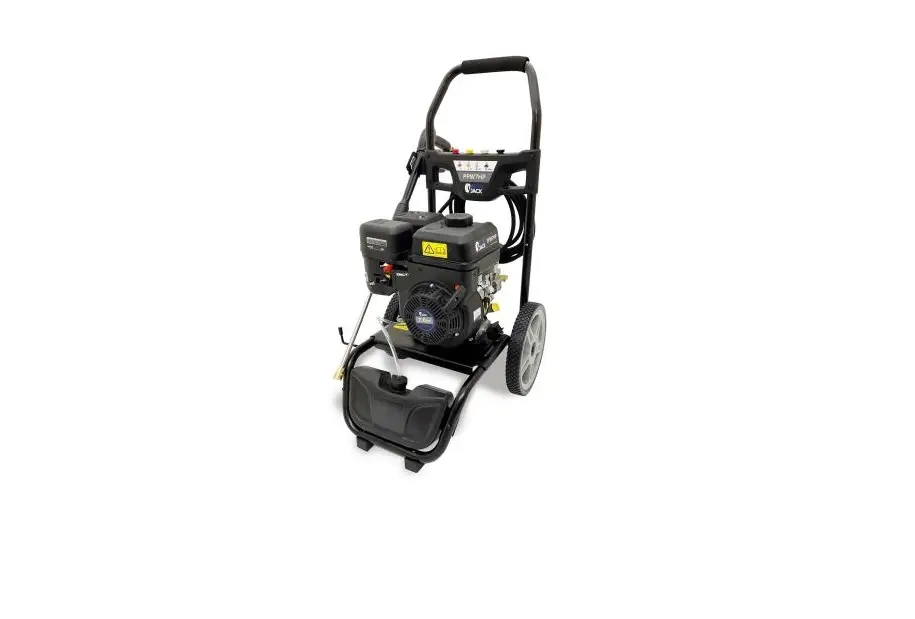
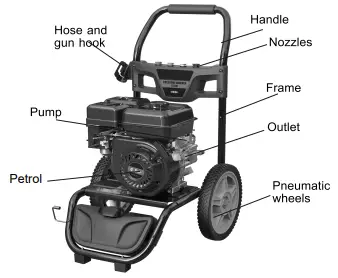
AUTO JACK PPW7HP Petrol Pressure Washer Owner’s Manual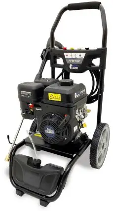
WARNING Read all safety warnings and
all instructions. Failure to follow the warnings and instructions may result in electric shock, fire and/or serious injury.
Save all warnings and instructions for future reference.
Work area safety
- Keep work area clean and well lit. Cluttered or dark areas invite accidents.
- Do not operate power tools in explosive atmospheres, such as in the presence of flammable liquids, gases or dust. Power tools create sparks which may ignite the dust or fumes.
- Keep children and bystanders away while operating a power tool. Distractions can cause you to lose control.
Personal safety
- Stay alert, watch what you are doing and use common sense when operating a power tool. Do not use a power tool while you are tired or under the influence of drugs, alcohol or medication. A moment of inattention while operating power tools may result in serious personal injury.
- Use personal protective equipment. Always wear eye protection. Protective equipment such as dust mask, non-skid safety shoes, hard hat, or hearing protection used for appropriate conditions will reduce personal injuries.
- Prevent unintentional starting. Ensure the switch is in the off position before connecting to power source and/or battery pack, picking up or carrying the tool. Carrying power tools with your finger on the switch or energising power tools that have the switch on invites accidents.
SYMBOL | DESCRIPTION |
| Read the manual before set-up and/or use. |
| Do not dispose with household waste. |
| Conforms to relevant safety standards. |
Technical Data:
| PPW7HP | |
| 3400 | |
| 207bar(3000PSI) | |
| 2.65GPM (10L/min) | |
| 7.0HP | |
| LT202H |
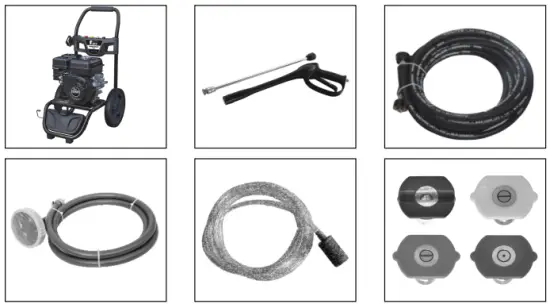
Includes:
Assembling
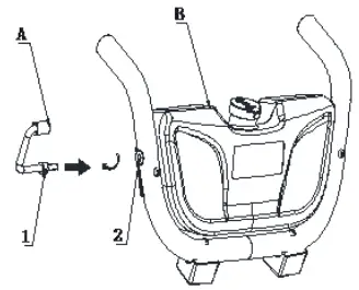
- Front stock and gun stock installation
a. Spare parts description:A. gun stock; B. Front stock; 1. M8_GB41 nut; 2. M8 bolt.
b. Installation description:Connect gun stock A clockwise to 2. M8_GB42 nut, after turning 8-10 time. Adjust the A. gun stock to position and tighten with 2. M8 bolt. shown in below image.
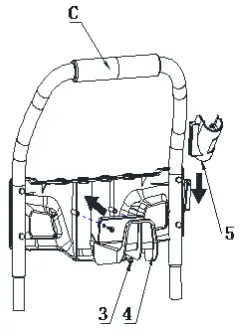
- Handle installation
a. Spare parts description:C. Handle; 3. Bolt ST4.8X20; 4. 790 hook;
5. Gun hoo
b. Installation description: On the C. Handle frame, slot the 5. Gun hoo into position. Place 4. 790 hook into the holes, then tighten with 3. Bolt ST4.8X20.
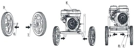
- Wheel installation
a. Spare parts description:D Wheel; E. Frame 6. Axle; 7. Gasket; 8. M8-1N
b. Installation description: assemble axle 6 into the wheel hole according to the arrow in P 3, assemble one gasket onto the axle as PIC 4, then plug the wheel with axle into the frame hole, pls check PIC 5, install and adjust gasket to the axle, screwing in M8-1 nut to tight the axle.
- Front stock installation
a. Spare parts description: 9. Ball
b. Installation description:install the front stock assembled in step 1 into the frame assembled step 3 as in PIC 7, to the ball position, press the ball as in PIC 7, then push the front stock again until you can listen a click sound and the ball stuck the front stock and frame.
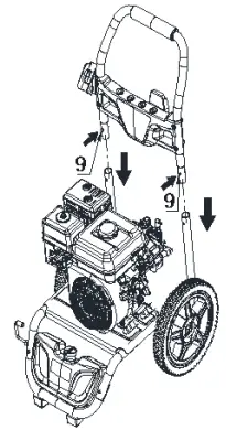
- Handle installation
a. Spare parts description:9. ball
b. Installation description:Install the C. handle assembled in step 1 into the frame assembled, to the 9. ball position, press the 9. ball, then push the C.
handle again until you can hear a click sound and the 9. ball connected to the frame.
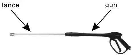
- Connect the lance to the gun. Tighten securely.

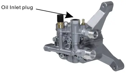
- Install oil inlet plug into pump, tighten securely. Check oil drain plug.


Using
- During operation of the machine, it is obligatory to use the appropriate personal safety equipment.
- During operation, please pay close attention to the information quoted on the chemical product labels regarding safety and the proper percentages to be used when diluting chemicals.
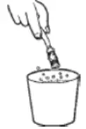
- Fill the detergent tank with the product you intend to use for your work and insert the detergent hose suction.
Repeat actions 1, 2 and 3 as per cold water use.
During operation, the detergent will be sucked up and automatically mixed with the water.
Avoid soaking with water the surface you then wish to treat with detergent because, in doing so, you can place a film of water over the area you wish to treat, resulting in poor cleaning results. Instead, whilst holding the nozzle pointing towards the ground, wait until the detergent exits the nozzle. When the detergent exits the nozzle, approach the surface you wish to treat, start from the bottom with overlapping strips until you reach the top of the area, sprinkling the whole area with detergent. This system is known to avoid dripping of detergent onto dry surfaces, the residue of which could remain even after rinsing.
In order to avoid the formation of deposits or crusts, at the end of operation it is advisable to pass clean water through the pump for a few seconds.
Troubleshooting
| PROBLEM | CAUSE | CORRECTION |
| Engine will not start(see Engine Manual for further engine troubleshooting) | No fuel. Low oil. Pressure builds up atter two pulls on the recoil starter or slier initial use. Choke lever in the “no choke” position. | Add fuel. Add required amount of oil. Squeeze gun trigger to relieve pressure. |
| Move choke to the “choke” position. | ||
| Spark plug wire not attached | Attach spark plug wire. | |
| Engine ON/OFF switch in OFF position. Choke lever in the “choke” position on a “hot ” engine or an engine that has been exposed to thermal heat fur a long period of time. Fuel valve closed. | Place engine ON/OFF switch in ON position. Move choke to the “NO CHOKE” position. Move fuel valve lever to the “open” position. | |
| No or low pressure (initial use) | Lance not in high pressure. Higher water supply. | Sec how to use lance paragragh in the operation section. Water supply must he less than 5.0 galtinin |
| Leak at high pressure water hose fitting. | Tighten. Apply sealant tape if necessary. a_ | |
| Nozzle obstructed. | See lance paragraph in the maintenance section for the correct procedure. | |
| Water filter screen clogged. | Remove and clean filter. | |
| Air in hose. | Turn off the enginc,then the water source. Disconnect the water source from the pump inlet and turn the water source on to remove all air from the hose. When there is a steady stream of water present, turn water source off. Reconnect water source to pump inlet and turn on water source. Squeeze trigger to remove remaining air. |
PUMP DIAGRAM
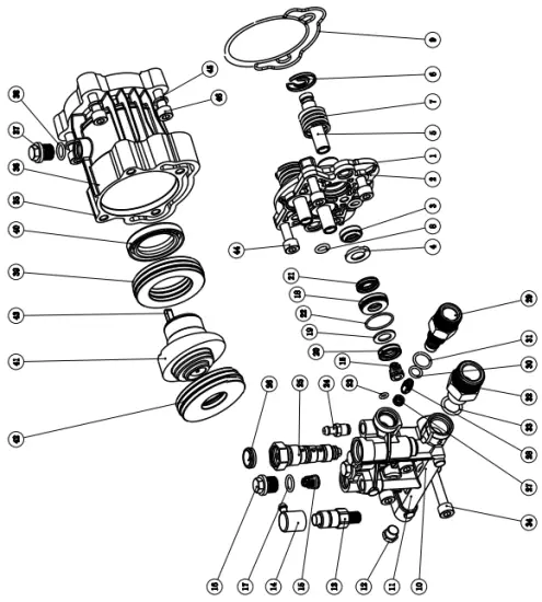
PUMP PARTS LIST
| 1 | Pump body assy | 1 | 27 | Water seal 12X20X5-2400PSI | 1 |
| 2 | Pump body | 1 | 28 | Water seal 12X20X4 | 1 |
| 3 | Plunger oil seal 12x20x5 | 3 | 29 | O ring 22X1_5/70HS/ROHS | 1 |
| 4 | Oil seal bracket | 3 | 30 | O ring 4.8X1.8/80HS/ROHS | 1 |
| 5 | Plunger | 3 | 31 | Siphon nozzle assy | 1 |
| 6 | Plunger plate | 3 | 32 | Detergent suction connector | 1 |
| 7 | Plunger spring | 3 | 33 | O ring 4X1.5/80HS/ROHS | 1 |
| 8 | O ring 9X2.4/70HS/ROHS | 2 | 34 | Stainless steel ball ¢5 | 1 |
| 9 | Special-shaped seal | 1 | 35 | Detergent suction spring | 1 |
| 10 | P202 Pump cover assy | 1 | 36 | O ring 6X1.5/80HS/ROHS | 1 |
| 11 | Brass pump cover | 1 | 37 | Relief valve assy | 1 |
| 12 | Cap G1/8 | 1 | 38 | Relief valve seat | 1 |
| 13 | Thermo valve G1/8-63℃ | 1 | 39 | O ring 8X2/80HS/ROHS | 1 |
| 14 | Thermo valve cover | 1 | 40 | Relief valve sleeve | 1 |
| 15 | Checking valve assy | 6 | 41 | Relief valve nut | 1 |
| 16 | Checking valve seat | 1 | 42 | Relief valve push rod | 1 |
| 17 | O ring 8.4X1.8/80HS/ROHS | 1 | 43 | Relief valve bolt | 1 |
| 18 | Checking valve plate | 1 | 44 | Relief valve gasket | 1 |
| 19 | Checking valve bracket | 1 | 45 | Relief valve spring 28.8 | 1 |
| 20 | Checking valve spring | 1 | 46 | O ring 12X2/95HS/ROHS | 1 |
| 21 | Checking valve cap assy | 3 | |||
| 22 | Checking valve cap | 1 | |||
| 23 | O ring 11X2/80HS/ROHS | 1 | |||
| 24 | Water seal assy | 3 | |||
| 25 | Water seal seat | 1 | |||
| 26 | Water seal gasket | 1 |
CE DECLARATION OF CONFORMITY
Autojack
Unit C, Manders Ind. Est., Old Heath Road, Wolverhampton, WV1 2RP.
Tel: 01902 450 470
Declares that the Petrol Pressure Washer (PPW7HP) Is in compliance with the regulations included in the Directives: 2014/35/EU
EC DECLARATION OF CONFORMITY
Certificate for EC-type examination delivered by Intertek Testing Services Hangzhou – 16 No. 1 Ave., Xiasha Economic Development District, Hangzhou 310018, China (Registration No.:190900418HZHV1)
Person who declares: Bill Evans

07.04.21
TOOLSAVE
UNIT C MANDERS INDUSTRIAL ESTATE WOLVERHAMPTON WV1 2RP


