![]() ITEM #4904933, 4904934
ITEM #4904933, 4904934
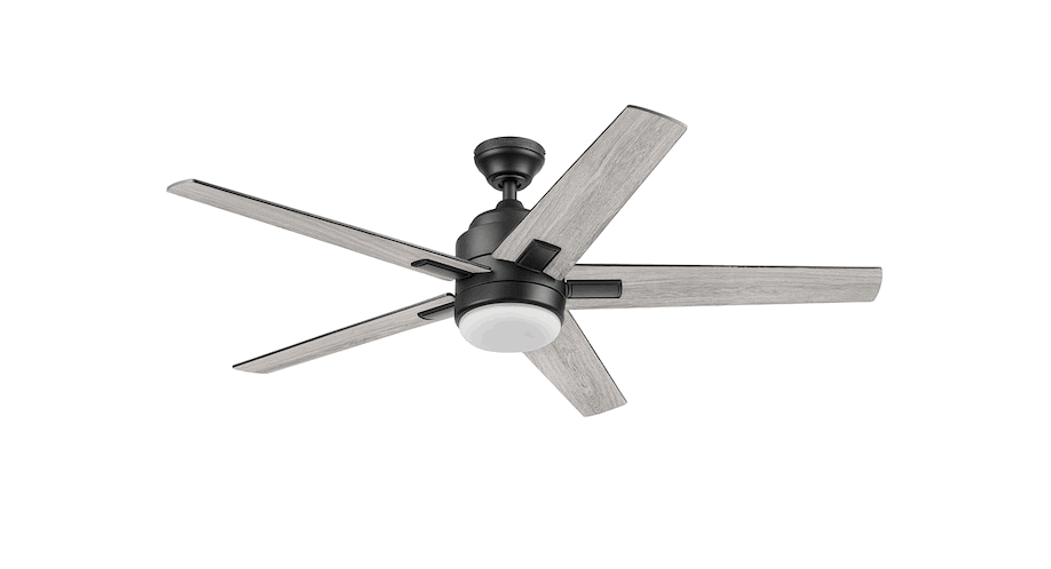
FLANAGAN XL CEILING FAN
MODEL #42610, 42611
![]()
42610 Flanagan Xl Ceiling Fan
HARBOR BREEZE and logo design are trademarks or registered trademarks of LF, LLC. All rights reserved.
ATTACH YOUR RECEIPT HERE
Purchase Date _______________ Questions, problems, missing parts? Before returning to your retailer, call our customer service department at 1-888-251-1003, 8 a.m. – 8 p.m., EST, Monday – Sunday. You could also contact us at [email protected].
SM21688
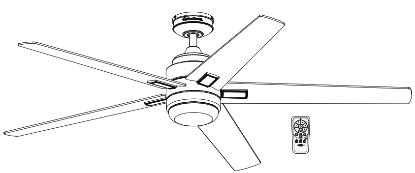
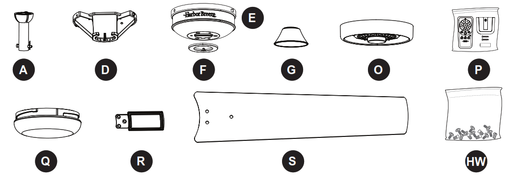
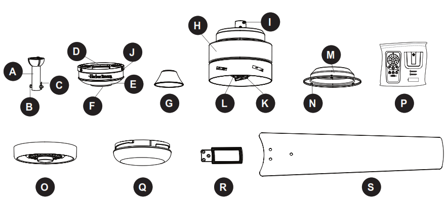
PACKAGE CONTENTS
| PART | DESCRIPTION | QUANTITY |
| A | Downrod | 1 |
| B | Downrod Pin (preassembled to the Downrod [A]) | 1 |
| C | Downrod Clip (preassembled to the Downrod [A]) | 1 |
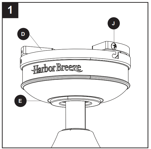
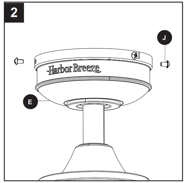
| D | Mounting Bracket (preassembled to Canopy [E]) | 1 |
| E | Canopy | 1 |
| F | Canopy Cover (preassembled to Canopy [E]) | 1 |
| G | Yoke Cover | 1 |
| H | Motor Assembly | 1 |
| I | Set Screw (preassembled to the Motor Assembly [H]) | 2 |
| J | Mounting Bracket Screw (preassembled to the Mounting Bracket [D]) | 4 |
| K | Fitter Plate (preassembled to the Motor Assembly [H]) | 1 |
| L | Fitter Plate Screw (preassembled to the Fitter Plate [K]) | 3 |
| M | Light Pan | 1 |
| N | Light Pan Screw (preassembled to the Light Pan [M]) | 3 |
| O | Light Kit | 1 |
| P | Remote Pack | 1 |
| Q | Glass Bowl | 1 |
| R | Blade Arm | 5 |
| S | Blade | 5 |
HARDWARE CONTENTS
(shown actual size)
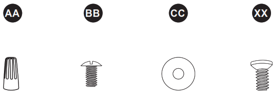 | |||
| Wire Connector Qty. 3 + 1 extra | Blade Screw Qty. 15 + 1 extra | Blade Washer Qty. 15 + 1 extra | Motor Screw Qty. 15 + 1 extra |
 SAFETY INFORMATION
Please read and understand this entire manual before attempting to assemble, operate or install the product.
- Before you begin installing the fan, disconnect the power by removing fuses or turning off the circuit breakers.
- Make sure all electrical connections comply with local codes, ordinances, the National Electrical Code and ANSI/NFPA 70-199. Hire a qualified electrician or consult a do-it-yourself wiring handbook if you are unfamiliar with installing electrical wiring.
- Make sure the installation site you choose allows a minimum clearance of 7 ft. from the blades to the floor and at least 30 in. from the end of the blades to any obstruction.
- The net weight of this fan is: 16.05lb (7.28kg).
![]() DANGER: When using an existing outlet box, make sure the outlet box is securely attached to the building structure and can support the full weight of the fan. Failure to do this can result in serious injury or death. The stability of the outlet box is essential in minimizing wobble and noise in the fan after installation is complete.
DANGER: When using an existing outlet box, make sure the outlet box is securely attached to the building structure and can support the full weight of the fan. Failure to do this can result in serious injury or death. The stability of the outlet box is essential in minimizing wobble and noise in the fan after installation is complete.![]() WARNING: To avoid personal injury, the use of gloves may be necessary while handling fan parts with sharp edges.
WARNING: To avoid personal injury, the use of gloves may be necessary while handling fan parts with sharp edges.![]() WARNING: Using a full-range dimmer switch to control fan speed will cause a loud humming noise from the fan. To reduce the risk of fire or electric shock, do NOT use this fan with any solid-state speed control device.
WARNING: Using a full-range dimmer switch to control fan speed will cause a loud humming noise from the fan. To reduce the risk of fire or electric shock, do NOT use this fan with any solid-state speed control device.![]() WARNING: To reduce the risk of fire, electric shock or personal injury, mount the fan to an outlet box marked “ACCEPTABLE FOR FAN SUPPORT” and use the mounting screws provided with the outlet box. Most outlet boxes commonly used for the support of lighting fixtures are not acceptable for fan support and may need to be replaced. Consult a qualified electrician if in doubt. Secure the outlet box directly to the building structure. The outlet box and its support must be able to support the moving weight of the fan (at least 35 lbs.).
WARNING: To reduce the risk of fire, electric shock or personal injury, mount the fan to an outlet box marked “ACCEPTABLE FOR FAN SUPPORT” and use the mounting screws provided with the outlet box. Most outlet boxes commonly used for the support of lighting fixtures are not acceptable for fan support and may need to be replaced. Consult a qualified electrician if in doubt. Secure the outlet box directly to the building structure. The outlet box and its support must be able to support the moving weight of the fan (at least 35 lbs.).![]() WARNING: To reduce the risk of fire, electric shock or personal injury, wire connectors provided with this fan are designed to accept only one 12-gauge house wire and two lead wires from the fan. If your house wire is larger than 12-gauge and/or there is more than one house wire to connect to the two fan lead wires, consult an electrician for the proper size wire connectors to use.
WARNING: To reduce the risk of fire, electric shock or personal injury, wire connectors provided with this fan are designed to accept only one 12-gauge house wire and two lead wires from the fan. If your house wire is larger than 12-gauge and/or there is more than one house wire to connect to the two fan lead wires, consult an electrician for the proper size wire connectors to use.![]() WARNING: To reduce the risk of fire, electric shock or personal injury, do not bend the blade arms when installing them, balancing the blades or cleaning the fan. Do not insert objects between the rotating fan blades.
WARNING: To reduce the risk of fire, electric shock or personal injury, do not bend the blade arms when installing them, balancing the blades or cleaning the fan. Do not insert objects between the rotating fan blades.![]() WARNING: To reduce the risk of personal injury, use only parts provided with this fan. The use of parts OTHER than those provided with this fan will void the warranty.
WARNING: To reduce the risk of personal injury, use only parts provided with this fan. The use of parts OTHER than those provided with this fan will void the warranty.
CAUTION: Read all instructions and safety information before installing your new fan. Review the accompanying assembly diagrams.
CAUTION: Be sure the outlet box is properly grounded or that a ground (green or bare) wire is present.
CAUTION: Carefully check all screws, bolts and nuts on the fan motor assembly to ensure they are secured.
CAUTION: This device complies with part 15 of FCC Rules. Operation is subject to the following two conditions: 1) This device may cause harmful interference, and 2) this device must accept any interference received, including interference that may cause undesired operation.
CAUTION: This equipment has been tested and found to comply with the limits for a Class B digital device, pursuant to Part 15 of the FCC Rules. These limits are designed to provide reasonable protection against harmful interference in a residential installation. This equipment generates, uses and can radiate radio frequency energy and, if not installed and used in accordance with the instructions, may cause harmful interference to radio communications. However, there is no guarantee that interference will not occur in a particular installation. If this equipment does cause harmful interference to radio or television reception, which can be determined by turning the equipment off and on, the user is encouraged to try to correct the interference by one or more of the following measures:
- Reorient or relocate the receiving antenna.
- Increase the separation between the equipment and receiver
- Connect the equipment into an outlet on a circuit different from that to which the receiver is connected.
- Consult the dealer or an experienced radio/TV technician for help.
Please note changes or modifications not expressly approved by the party responsible for compliance could void the user’s authority to operate the equipment.
PREPARATION
Before beginning the assembly of this product, ensure that all parts are present. Compare all parts with the package contents list and hardware contents list. If any part is missing or damaged, do not attempt to assemble the product.
Estimated Assembly Time: 120 minutes
Tools Required for Assembly (not included): Electrical Tape, Phillips Screwdriver, Pliers, Safety Glasses, Step Ladder, Wire Cutters and Wire Strippers
Helpful Tools (not included): AC Tester Light, Tape Measure and Wiring Handbook
INITIAL INSTALLATION
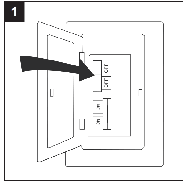
- Turn off the circuit breakers and the wall switch to the fan supply line leads.
DANGER: Failure to disconnect the power supply prior to installation may result in serious injury or death.
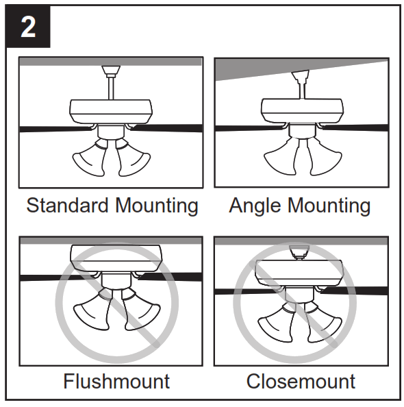
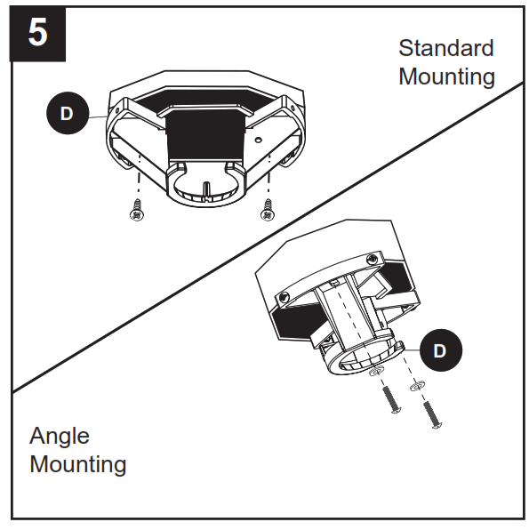
- Determine the mounting method to use.
Standard Mounting is best suited for ceilings 8 ft. or higher. For taller ceilings you may want to use a longer downrod (not included).
Angle Mounting is best suited for angled or vaulted ceilings. A longer downrod is sometimes necessary to ensure proper blade clearance.
Important: If using the angle mount, check to ensure the ceiling angle is not steeper than 16°.
Flushmount is not available for this item.
Closemount is not available for this item.
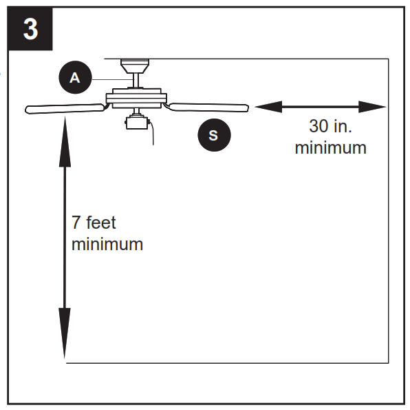
- Ensure the blades (S) will be at least 30 in. from any obstructions. Also check the downrod (A) length to ensure the blades (S) will be at least 7 ft. above the floor.

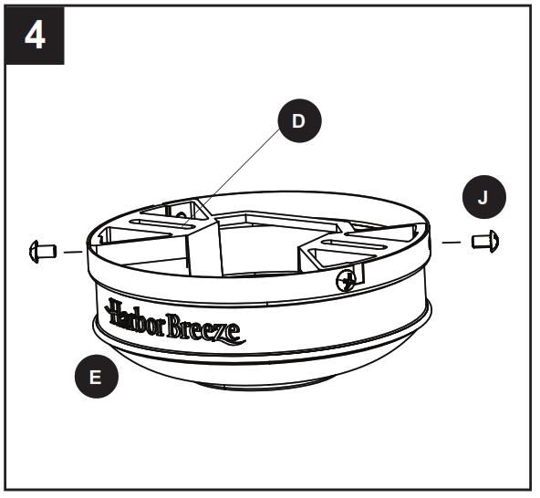
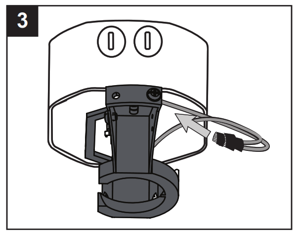
- Loosen all four preassembled mounting bracket screws (J), then completely remove the two mounting bracket screws (J) from the round holes of canopy (E). Set aside for later use. Turn the canopy in a counterclockwise direction. Detach mounting bracket (D) from canopy (E).

- Attach mounting bracket (D) to outlet box (not included) using screws and washers provided with the outlet box.
CAUTION: It is very important to use the proper hardware when installing the mounting bracket (D) as this will support the fan.
STANDARD OR ANGLE MOUNTING INSTRUCTIONS
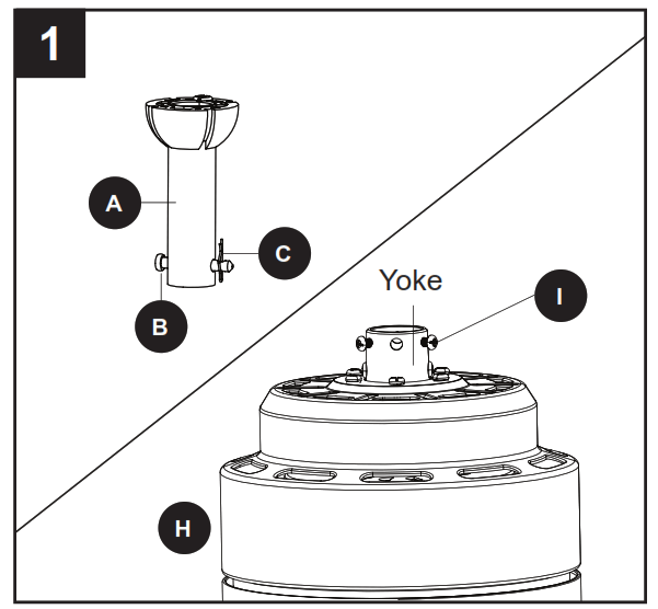
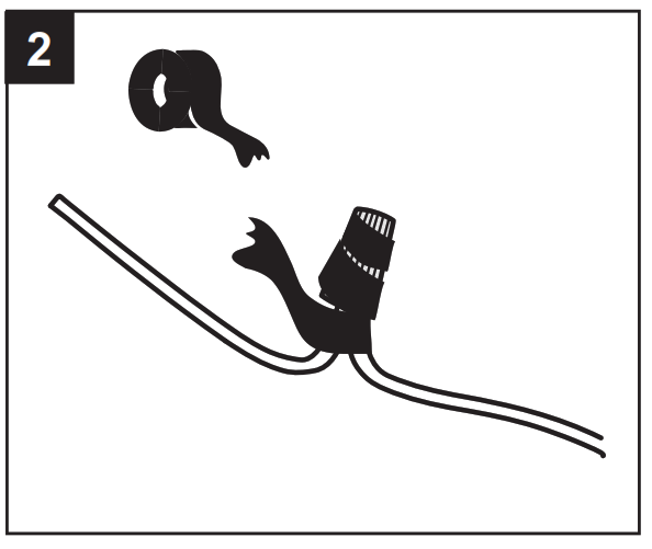
- Remove the downrod clip (C) and downrod pin (B) from the downrod (A). Then partially loosen the set screws (I) in the yoke at the top of the motor assembly (H).

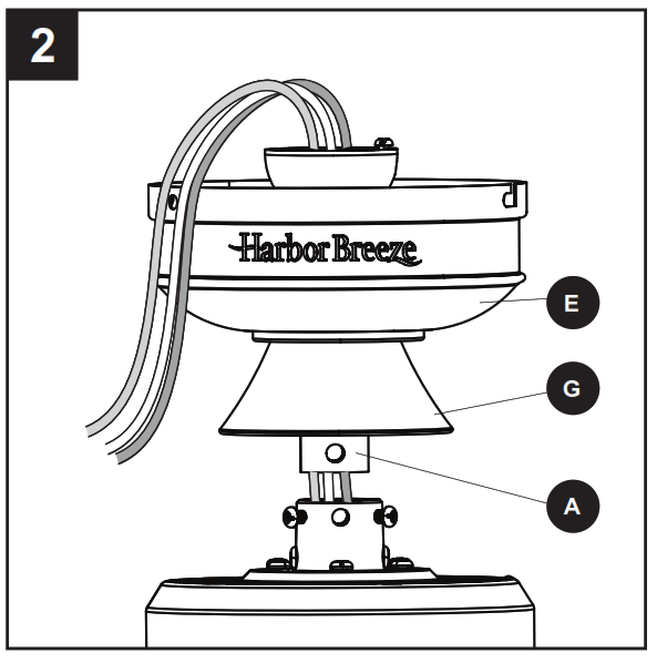
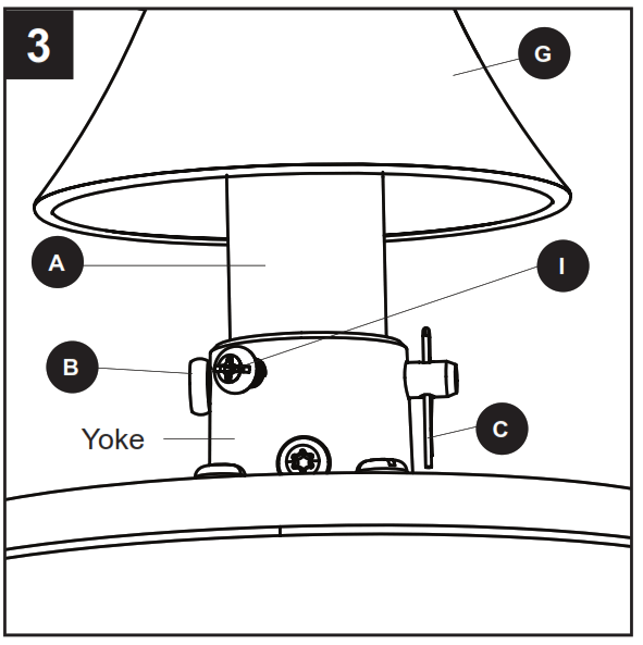
- Insert the downrod (A) — or a longer downrod (not included), if required — through the canopy (E) and yoke cover (G). Feed the wires from the fan through the downrod (A).

- Slide the downrod (A) into the yoke, align the holes, then re-install the downrod pin (B) and downrod clip (C). Secure with set screws (I) and slide the yoke cover (G) down until it rests on top of the motor assembly (H).

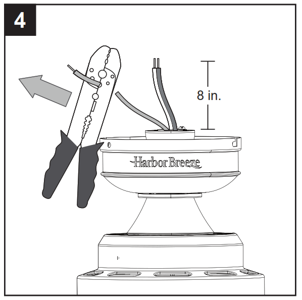
- Depending on the length of downrod you use, you may need to cut the lead wires back to simplify the wiring. If you decide to cut back the lead wires, it is suggested you do so in the following manner: Take the lead wires and make sure you have pulled them all the way through the top of the downrod. Measure 8 inches of lead wire, then cut the excess wire off with wire cutters (not included).

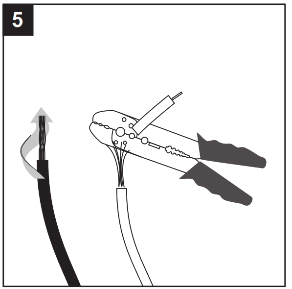
- If you decided to cut back the lead wire in Step 4, strip 1/2 in. of insulation from the end of the white wire. Twist the stripped ends of each strand of wire within the insulation with pliers (not included). Repeat the step for the black wire.
Note: If you did not cut back the lead wires in Step 4, Step 5 is not necessary and you may proceed to Step 6 instead.
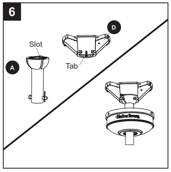
- Install the ball end of the downrod (A) into the opening of the mounting bracket (D). Align a slot in the ball with the tab in the mounting bracket (D).
Important: The downrod (A) should not rotate in the mounting bracket (D) if installed properly. DANGER: Failure to align a slot in the ball with the tab may cause the fan to wobble or fall, which could result in serious injury or death.
WIRING
![]() WARNING: To reduce the risk of fire, electrical shock or personal injury, wire connectors provided with this fan are designed to accept only one 12-gauge house wire and two lead wires from the fan. If your house wire is larger than 12-gauge and there is more than one house wire to connect to the two fan lead wires, consult an electrician for the proper size wire connectors to use.
WARNING: To reduce the risk of fire, electrical shock or personal injury, wire connectors provided with this fan are designed to accept only one 12-gauge house wire and two lead wires from the fan. If your house wire is larger than 12-gauge and there is more than one house wire to connect to the two fan lead wires, consult an electrician for the proper size wire connectors to use.
CAUTION: Be sure the outlet box is properly grounded or that a ground (green or bare) wire is present.
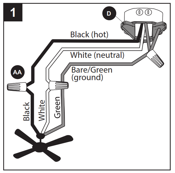
- Connect household supply and fan wires according to the diagram and these steps:
• Connect the Green wire from downrod (A) and mounting bracket (D) to the Bare/Green supply wire.
• Connect the White wire from the fan to the White supply wire.
• Connect the Black wire from the fan to the Black supply wire.
• Secure all wiring connections together with wire connectors (AA).
Note: The Black wire is hot power for the fan. The White wire is common for the fan and light kit. The Green wire is the ground wire. If household supply wires are different colors than referred to above, it is recommended a professional electrician determines the proper wiring. Hardware Used
- Wrap electrical tape (not included) around each individual wire connector (AA) down to the wire.

- Turn the spliced/taped wires upward and gently push the wires and wire connectors (AA) into the outlet box. WARNING: Ensure no bare wire or wire strands are visible after making connections. Place the Green and White wire connections on the opposite side of the outlet box from the Black wire connections.

 Hardware Used
FINAL INSTALLATION
- Align the canopy (E) over the loose mounting bracket screws (J) preassembled on mounting bracket (D). Place the keyholes of the canopy (E) onto the mounting bracket screws (J) and rotate the canopy (E) clockwise.
- Secure the canopy (E) with the mounting bracket screws (J) previously removed (Step 4, page 8). Tighten all mounting bracket screws (J) securely.

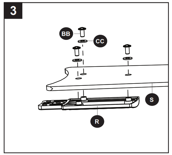
- Partially insert the blade screws (BB) along with the blade washers (CC) through the blade (S) and into the blade arm (R). Tighten each blade screw (BB) with a Phillips screwdriver (not included), starting with the one in the middle. Repeat this step for the remaining blades (S) and blade arms (R).
 Hardware Used
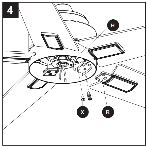
- Insert blade arm (R) through slot in the side of the motor assembly (H). Align the holes of one blade arm (R) with three motor screw holes in underside of the motor assembly (H). Secure with three motor screws (XX). Repeat this step for the remaining blade arms (R).
 Hardware Used
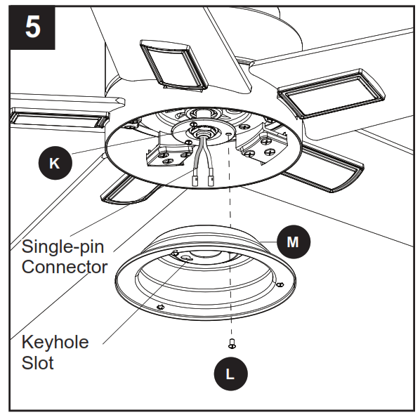
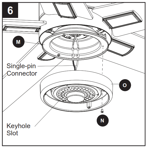
- Remove one and loosen the other two fitter plate screws (L) but do not remove from fitter plate (K). Feed the single-pin connector through center hole in light pan. Align the two keyhole slots in the light pan (M) with the loosened fitter plate screws (L). Place the light pan (M) over the two screws and turn the light pan (M) clockwise. Then tighten the two fitter plate screws (L). Re-install the fitter plate screw (L) that was removed in the previous step and tighten firmly.

- Remove one and loosen the other two light pan screws (N) from the underside of the light pan (M). Connect the single-pin connector from the fitter plate (K) to the single-pin connector from the light kit (O) — blue to black and white to white. Align the keyhole slots in the light kit (O) with the loosened screws in the light pan (M). Turn light kit (O) clockwise and replace the previously removed light pan screw (N). Tighten all screws.

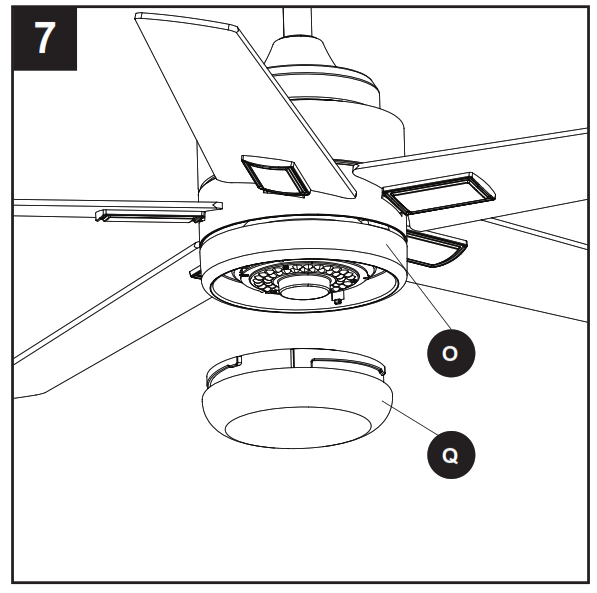
- Attach the glass bowl (Q) to the light kit (O) by twisting the glass bowl (Q) tightly in a clockwise direction until it is secure. CAUTION: Avoid cross-threading the glass during installation. Improper installation could cause the glass bowl (Q) to be difficult to remove or fall, which could cause serious injury.

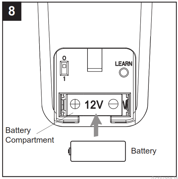
- Remove the battery cover from the back of the remote found in remote pack (P). Insert the battery from remote pack (P) into the remote; ensure polarity of battery matches the polarity indicated in the battery compartment — positive (+) to positive (+) and negative (-) to negative (-). Replace the battery cover and press the high fan speed button on the remote to ensure the remote turns on the fan.
Note: If remote doesn’t turn on the fan, see TROUBLESHOOTING (page 17).
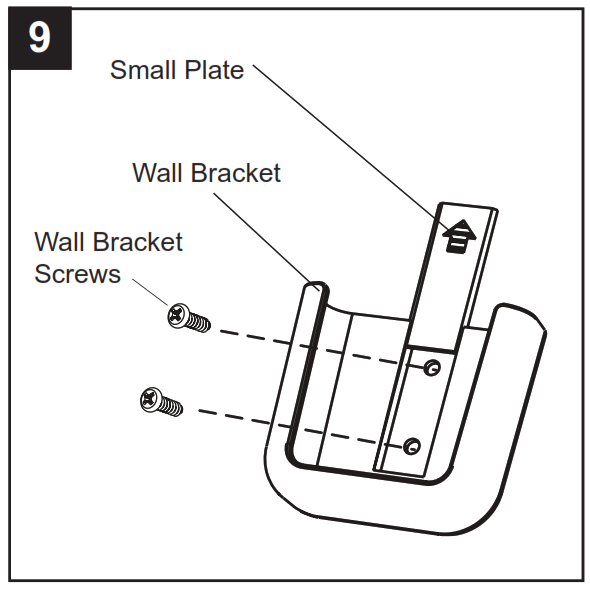
- Remote control (P) comes equipped with a wall bracket. If you wish to install the wall bracket, remove the small plate to expose the screw holes. Insert wall brackets screws through holes and into wall, then cover with the previously removed small plate. Remote control (P) sits inside the wall bracket.
 Turn on the circuit breakers and the wall switch to the fan supply line leads.
Assembly is complete.
 Hardware Used
 Hardware Used
 Turn on the circuit breakers and the wall switch to the fan supply line leads.
OPERATING INSTRUCTIONS
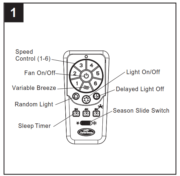
- To operate the fan using remote control (P), press and release the following buttons:
 Speed Control – Controls fan speed 1 (low) – 6 (high).
Fan On/Off – Turns fan off or turns fan on at most recently selected speed. Press and hold to turn off or on the sounds from the remote control.
Variable Breeze – Simulates a natural breeze, as if you were outside. Press any speed control button to exit this mode.
Random Light – When button is pressed, light blinks twice to confirm Random Light mode. Lights cycle on for 5-20 minutes and off for 60 minutes. Cycle repeats continuously until any other button is pushed to discontinue Random Light mode.
Sleep Timer – Turns fan off after (2H) 2 hours, (4H) 4 hours or (8H) 8 hours.
Light On/Off – Turns the light on and off. Press and hold to dim or brighten lights (for dimmable bulbs only).
Delayed Light Off – Delays turning off light for one minute which allows safe exit from room.
Season Slide Switch – Changes direction of blade rotation. For warm weather slide switch to the left and for cool weather slide switch to the right. - Remove battery door from back of the remote control (P) to access the following:DIP Switch – Changes signal frequency if there is interference from another remote (see troubleshooting for instructions).
Learn – Syncs remote control (P) to receiver (see troubleshooting for instructions).
Battery Compartment – When necessary, replace the pre-installed battery with a new 12-volt battery.
 Speed Control – Controls fan speed 1 (low) – 6 (high).
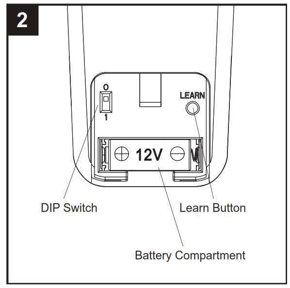 DIP Switch – Changes signal frequency if there is interference from another remote (see troubleshooting for instructions).
CARE AND MAINTENANCE
At least twice each year, lower the canopy to check the downrod assembly, and then tighten all screws on the fan. Clean the motor housing with only a soft brush or lint-free cloth to avoid scratching the finish. Clean the blades with a lint-free cloth.
Total fixture wattage is 22.5 watts; do not attempt to replace LED.
Battery Replacement: Use A23 12-volt battery. Exhausted batteries should be removed from the remote. Non-rechargeable batteries should not be recharged. Do not dispose of batteries in fire, as they may explode or leak.
Important: Shut off the main power supply before you begin any maintenance tasks. Do not use water or a damp cloth to clean the ceiling fan.
TROUBLESHOOTING
| PROBLEM | POSSIBLE CAUSE | CORRECTIVE ACTION |
| The fan does not move. | 1. The power is off, or the fuse is blown. 2. There is a faulty wire connection. 3. The plugs are not connected properly. 4. The reverse switch is not completely engaged. | 1. Turn the power on or check the fuse. 2. Turn the power off. Loosen the canopy and check all connections. 3. Check that the connectors from the light kit fitter and fan are connected properly. 4. Push the reverse switch completely to the left or right. |
| The fan is noisy. | 1. The blades are loose. 2. There is a cracked blade. 3. The wall control is not compatible with the fan. 4. The outlet box is not secure. 5. The mounting bracket is not secure. | 1. Check and tighten all screws that hold the fan blades to the blade arms and the motor. 2. Replace the cracked blade. 3. Do not use a full range dimmer switch to control the fan speed. 4. Ensure the outlet box is secured to the building structure. 5. Ensure the mounting bracket is secured to the outlet box and that the screws are tight. |
| PROBLEM | POSSIBLE CAUSE | CORRECTIVE ACTION |
| There is excessive wobbling. | 1. The blades and/or blade arms are loose. 2. The blades are unbalanced. 3. The fan mounting is not secure. 4. The fan is too close to the vaulted ceiling. 5. The set screw on the motor housing yoke is loose. | 1. Check and tighten all screws that hold the fan blades to the blade arms and the blade arms to the motor. 2. Switch one blade with a blade from the opposite side. Or balance the fan using a blade balancing kit (sold separately). 3. Turn off the power. Loosen the canopy and verify that the mounting bracket is secure to the electrical outlet box. The bracket must be flush without movement against the outlet box. 4. Use a longer downrod (sold separately) or move the fan to another location. 5. Lift up the yoke cover and tighten the set screw to the yoke until secure. |
| The fan operates correctly, but the lights are not working. | 1. The light kit wire plugs are not connected properly. 2. There is a faulty wire connection. | 1. Ensure that the single-pin connectors from the light kit are connected properly. 2. Turn the power off and check all connections at the ceiling outlet box. |
| Remote control does not work. | 1. Power surge may have cleared memory and remote needs to be re-synced to the receiver. 2. Battery in remote control needs to be replaced. 3. Interface from another remote. | 1. After installation is complete, switch the power off and back on again. Within 30 seconds, remove the battery from remove pack (P). Press and hold the “LEARN” button, located in the battery compartment, for 5 seconds. Fan will turn on at low speed and light (if installed) off. This confirms that the SMART SYNC is active. 2. Insert new 12V battery in battery compartment of the remote control (see page 14). 3. If there are several fans in close proximity, turn power off to other fans and re-sync the remote (see Corrective Action 1 above). |
LIMITED LIFETIME WARRANTY
The manufacturer warrants this fan to be free from defects in workmanship and materials present at time of shipment from the factory for a lifetime from the date of purchase by the original purchaser.
The retailer also warrants that all other fan parts, excluding any glass or plastic blades, to be free from defects in workmanship and material at the time of shipment from the factory for a period of one year after the date of purchase by the original purchaser. The manufacturer agrees to correct such defects without charge or at its option replace the ceiling fan with a comparable or superior model. To obtain warranty service, present a copy of the receipt as proof of purchase. All costs of removing and reinstalling the product are your responsibility. Any damage to any part such as by accident or misuse or improper installation or by affixing any accessories, is not covered by this warranty. The manufacturer assumes no responsibility whatsoever for fan installation during the limited lifetime warranty. Any service performed by an unauthorized person will render the warranty invalid.
Due to varying climate conditions, this warranty does not cover any changes in brass finish, including rusting, pitting, corroding, tarnishing or peeling. Brass finishes of this type give their longest useful life when protected from varying weather conditions. Any glass provided with this fan is not covered by the warranty.
Any replacement of defective parts from the ceiling fan must be reported within the first year from the date of purchase. For the balance of the warranty, call our customer service department for return authorization and shipping instructions so that we may repair or replace the ceiling fan. Any fan or parts returned improperly is the sole responsibility of the purchaser. There is no other expressed warranty. The manufacturer disclaims any and all warranties. The duration of any implied warranty which cannot be disclaimed is limited to the time period as specified in the expressed warranty. The manufacturer shall not be liable for incidental, consequential, or special damages arising out of or in connection with product use or performance except as may otherwise be accorded by law. This warranty gives specific legal rights, and you may also have other rights which vary from state to state.
This warranty supersedes all prior warranties.
Note: A small amount of “wobble” is normal and should not be considered a defect.
REPLACEMENT PARTS LIST
For replacement parts, call the customer service department at 1-888-251-1003, 8 a.m. – 8 p.m., EST, Monday – Sunday. You could also contact us at [email protected].
| PART | DESCRIPTION | #4904933 | #4904934 |
| A | Downrod | 4L000006400 | 4L000013340 |
| D | Mounting Bracket | 4L000007490 | 4L000008860 |
| E | Canopy | 4L000007510 | 4L000014940 |
| F | Canopy Cover | 4L000000830 | 4L000010400 |
| G | Yoke Cover | 4A000005540 | 4A000009350 |
| O | Light Kit | 4L000015690 | 4L000015700 |
| P | Remote Pack | 4L000015680 | 4L000015680 |
| Q | Glass Bowl | 4L167520001 | 4L167520001 |
| R | Blade Arm (x5) | 4L074400002 | 4L074400001 |
| S | Blade (x5) | 4L086220002 | 4L086220001 |
| HW | Hardware Kit | 4L000015710 | 4L000015720 |
![]() HKC-US
HKC-US
3350 Players Club Parkway, Suite 225
Memphis, TN 38125
1-888-251-1003
9766-PB
122621
Printed in China


