
![]() SL302 SmartStart LTE Industrial Router
SL302 SmartStart LTE Industrial Router
User Manual
© 2022 Advantech Czech s.r.o. No part of this publication may be reproduced or transmitted in any form or by any means, electronic or mechanical, including photography, recording, or any information storage and retrieval system without written consent. Information in this manual is subject to change without notice and does not represent a commitment on the part of Advantech.
Advantech Czech s.r.o. shall not be liable for incidental or consequential damages resulting from the furnishing, performance, or use of this manual.
All brand names used in this manual are the registered trademarks of their respective owners. The use of trademarks or other designations in this publication is for reference purposes only and does not constitute an endorsement by the trademark holder.
Used symbols
 Danger – Information regarding user safety or potential damage to the router.
![]() Attention – Problems that can arise in specific situations.
Attention – Problems that can arise in specific situations.![]() Information, notice – Useful tips or information of special interest.
Information, notice – Useful tips or information of special interest.
GPL license
Source codes under the GPL license are available at https://icr.advantech.cz/source-code address.
![]()
Advantech Czech s.r.o., Sokolska 71, 562 04 Usti nad Orlici, Czech Republic
Document No. MAN-0002-EN, a revision from July 25, 2022. Released in the Czech Republic.
Safety Instructions
![]() Please, observe the following instructions:
Please, observe the following instructions:
- The router must be used in compliance with all applicable international and national laws and in compliance with any special restrictions regulating the utilization of the router in prescribed applications and environments.
- To prevent possible injury and damage to appliances and to ensure compliance with all relevant provisions, use only the original accessories. Unauthorized modifications or the use of unapproved accessories may result in damage to the router and/or a breach of applicable regulations. Unauthorized modifications or the use of unapproved accessories may void the warranty.
- The router can not be opened.
- Turn off the router and disconnect it from the power supply before handling the SIM card.
 Caution! This equipment is not suitable for use in locations where children are likely to be present. The SIM card could be swallowed by small children.
- Input voltage must not exceed 36 V DC max.
- Do not expose the router to extreme ambient conditions. Protect the router against dust, moisture, and high temperature.
- Only routers with appropriate certification and labeling should be used in locations where flammable and explosive materials are present, including gas stations, chemical plants, or locations in which explosives are used. We remind users of the duty to observe the restrictions concerning the utilization of radio devices at such places.
- Switch off the router when traveling by plane. Utilization of the router on a plane may endanger the operation of the plane or interfere with the mobile telephone network and may be unlawful. Failure to observe these instructions may result in the suspension or cancellation of telephone services for the respective client and/or may result in legal sanctions.
- When using the router in close proximity to personal medical devices, such as cardiac pacemakers or hearing aids, you must proceed with heightened caution.
- The router may cause interference when used in close proximity to TV sets, radio receivers or personal computers.
- It is recommended that you create an appropriate copy or backup of all important settings that are stored in the memory of the device.
Directives and Statements
Product Disposal Instructions
The WEEE (Waste Electrical and Electronic Equipment: 2012/19/EU) directive was introduced to ensure that electrical/electronic products are recycled using the best available recovery techniques to minimize the impact on the environment. This product contains high-quality materials and components which can be recycled. At the end of its life, this pro- duct MUST NOT be mixed with other commercial waste for disposal. The device contains a battery.
Remove the battery from the device before disposal. The battery in the device needs to be disposed of apart accordingly. Check the terms and conditions of your supplier for disposal information.
FCC Compliance Statement
This device complies with part 15 of the FCC Rules. Operation is subject to the following two conditions: (1) This device may not cause harmful interference, and (2) this device must accept any interference received, including interference that may cause undesired operation.
Warning: Changes or modifications to this unit not expressly approved by the party responsible for compliance could void the user’s authority to operate the equipment.
This device complies with Industry Canada license-exempt RSS standard(s). Operation is subject to the following 2 conditions: (1) this device may not cause interference, and (2) this device must accept any interference, including interference that may cause undesired operation of the device.
This equipment has been tested and found to comply with the limits for a Class B digital device, pursuant to Part 15 of the FCC Rules. These limits are designed to provide reasonable protection against harmful interference in a residential installation. This equipment generates, uses, and can radiate radio frequency energy and, if not installed and used in accordance with the instructions, may cause harmful interference to radio communications. However, there is no guarantee that interference will not occur in a particular installation. If this equipment does cause harmful interference to radio or television reception, which can be determined by turning the equipment off and on, the user is encouraged to try to correct the interference by one or more of the following measures:
- Reorient or relocate the receiving antenna.
- Increase the separation between the equipment and receiver.
- Connect the equipment to an outlet on a circuit different from that to which the receiver is connected.
- Consult the dealer or an experienced radio/TV technician for help.
Important: Changes or modifications to this product not authorized by Advantech Czech could void the electromagnetic compatibility (EMC) and wireless compliance and negate your authority to operate the product. This product has demonstrated EMC compliance under conditions that included the use of compliant peripheral devices and shielded cables between system components. It is important that you use compliant peripheral devices and shielded cables between system components to reduce the possibility of causing interference to radios, televisions, and other electronic devices.
Router Description
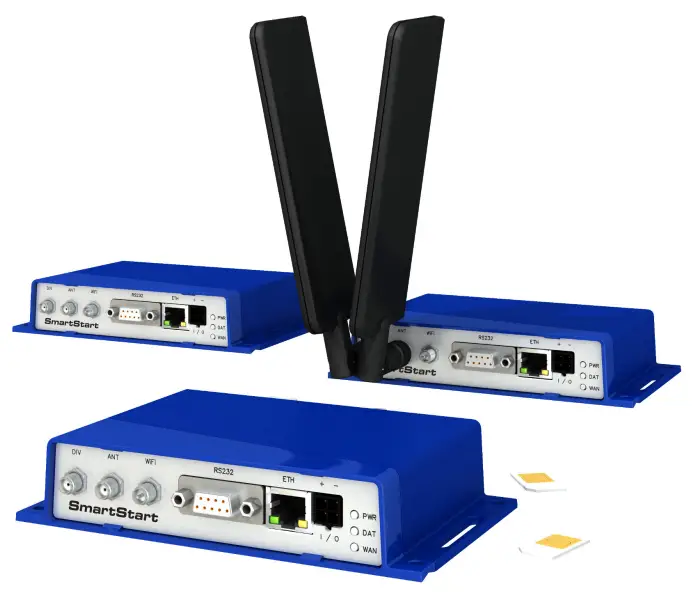
Cellular router SmartStart SL302 is designed for wireless communication in mobile networks that use traditional cellular technologies. The primary purpose of this router is its use in the newest Category 1 (Cat.1) services on the cellular LTE network of the AT&T and Verizon carriers.
LTE Category 1 (Cat.1)
Given the uncertain future of 2G technologies (they are gradually sunsetting), it needs to find a suitable (natural) replacement. LTE Category 1 (Cat.1) in general is the only real alternative to 2G. It is specifically designed to bring 4G LTE capabilities to the Internet of Things (IoT) and machine-to-machine (M2M) applications. Like all LTE services, Cat.1 provides a low-latency broadband connection but is capped at 10 Mbps download (and 5 Mbps upload). It is an ideal solution for smart meters for utilities, telematics for vehicle tracking, and fleet management and security use cases, such as in alarm systems.
3.2 Basic HW Information
As a standard, the SmartStart router is equipped with one Ethernet 10/100 Mbps, one serial interface RS232, one binary input, and one output. SL302 also contains two readers for 3 V and 1.8 V SIM cards, which are placed on the rear panel of the device. The router can be equipped with a WiFi module, but this must be part of the initial configuration – it cannot be assembled to the router at some point in the future. The router is supplied in a plastic casing.
3.3 Configuration and Diagnostics
The router can be configured using a password-protected Web interface. The web interface provides (after logging in) detailed statistics about the router activities, signal strength, detailed system logs, etc. This device supports the creation of VPN tunnels using technologies IPSec, OpenVPN, and L2TP for secure communications. There are also supported functions such as IPv6 (the latest revision of the Internet Protocol), DHCP, NAT, NAT-T, DynDNS, NTP, VRRP, control by SMS, primary connection backups, and many other functions are also supported.
Other diagnostic functions ensuring continuous communication include automatic inspection of PPP connection offering an automatic restart feature in case of connection is lost, or a hardware watchdog that monitors the status of the router. Using a special window (start-up script window) you may insert Linux scripts for various actions. For some applications is the key possibility to create several different configurations for one router which can be switched as needed (e.g. using SMS or status of the binary input). Cellular routers may automatically update configuration and firmware from the server. This allows mass reconfiguration of many routers at one time.
The router also supports additional software such as R-SeeNet for permanent traffic monitoring of routers.
![]() Examples of possible applications
Examples of possible applications
| • mobile office • smart meters for utilities • fleet management • security systems | • telematic • telemetric • remote monitoring • vending and dispatcher machines |
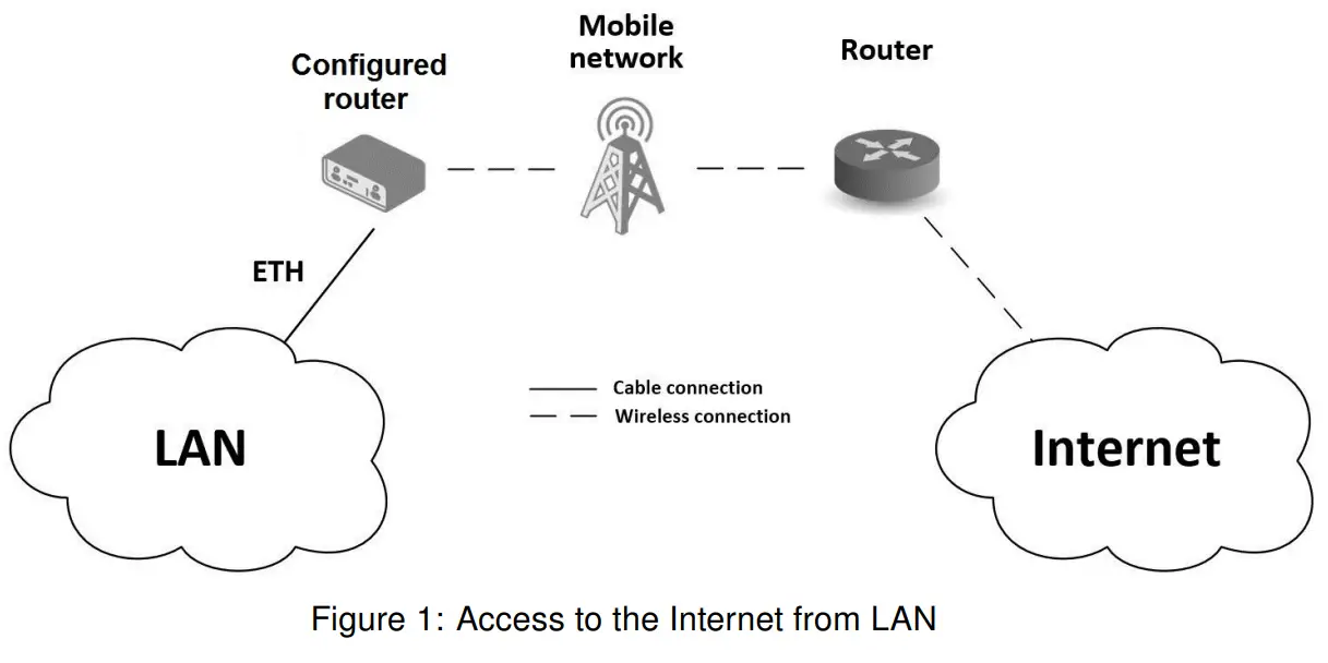
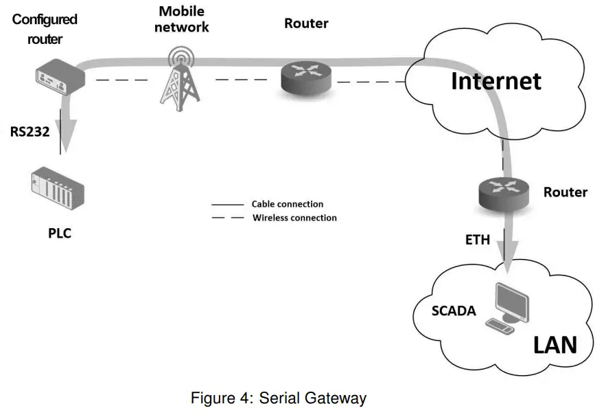
3.4 Usage of the Router
The router is primarily intended for these four basic situations:
Access to the Internet from LAN
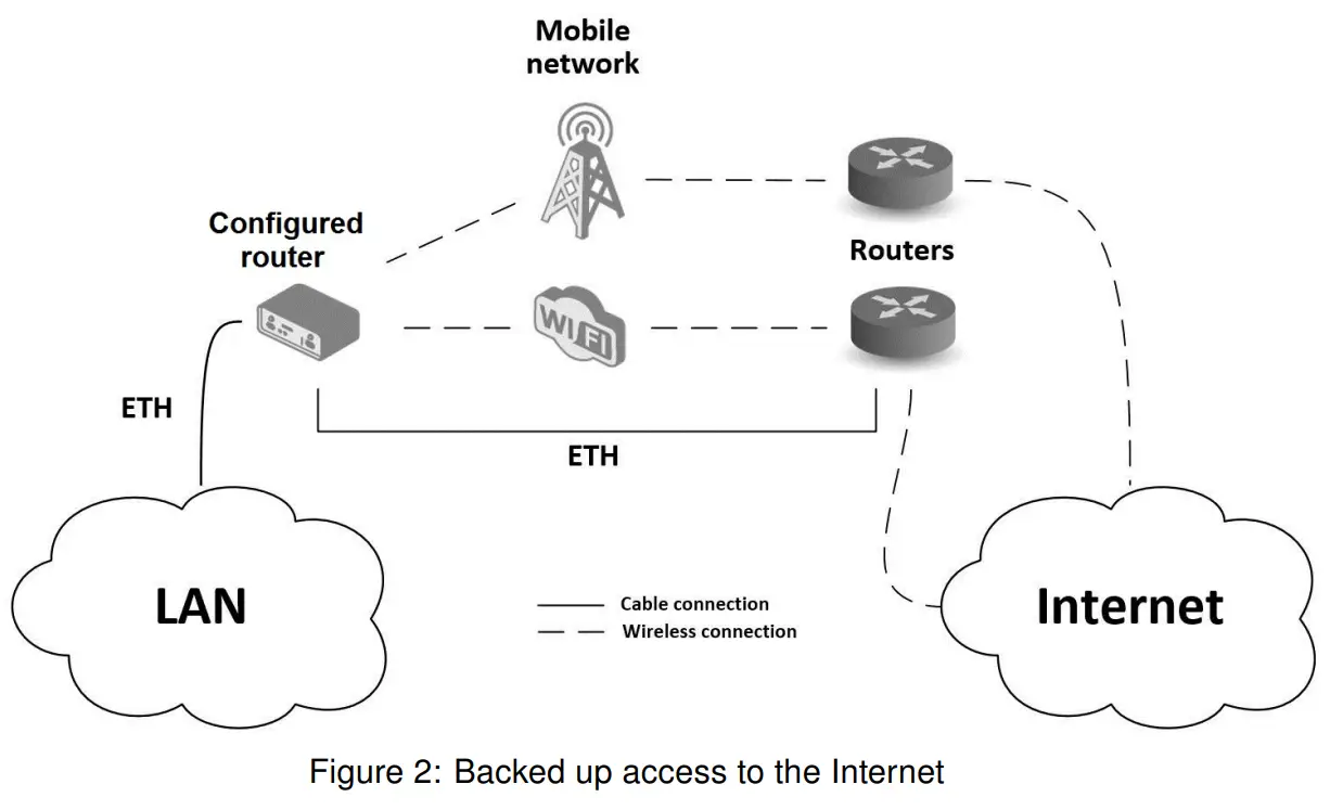
Backed up access to the Internet (from LAN)
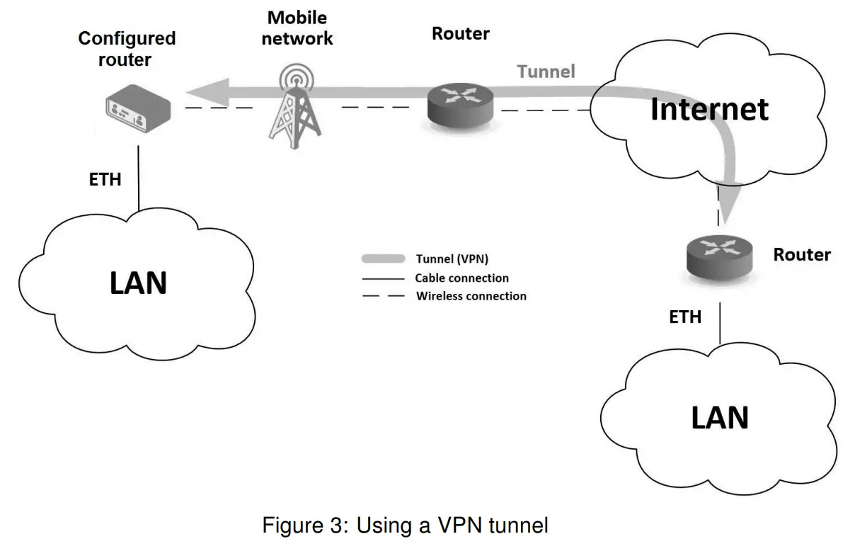
 Secure networks interconnection or use VPN
Serial Gateway
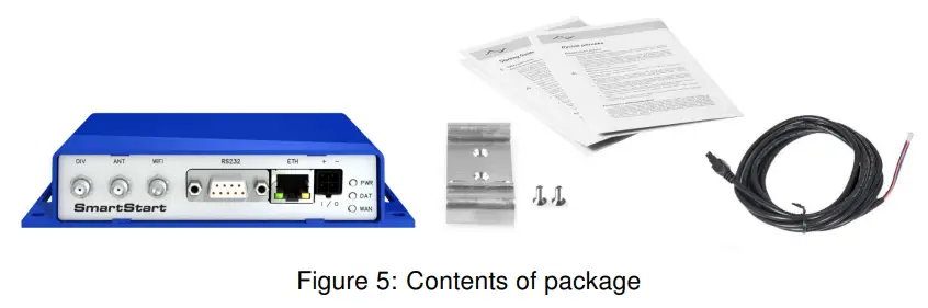
Contents of Package
The basic router set available for delivery includes the following items:
- router,
- power and IO cable (1.5 m long),
- clip for the DIN rail (two screws are included),
- paper start guide.
 Router Design
 Router Design
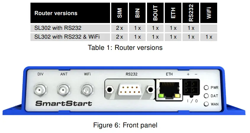
5.1 Router Versions
The SmartStart SL302 router is supplied in the following versions (see table below). All versions are available only in plastic casing.
 5.2 Delivery Identification
| Trade name | Product name | Description |
| SL302 | SmartStart | LTE router (Cat.1) for NAM (AT&T and/or Verizon carrier – see order codes below) |
Table 2: Delivery identification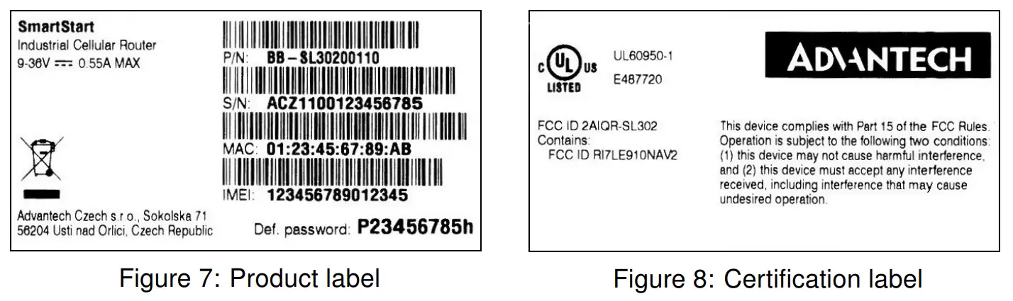 5.3 Order Codes
The table below shows an overview of order codes.
| Name | Order code | Features – interfaces |
| SmartStart SL302 | BB-SL30200010 | LTE module Cat.1 AT&T, 1x ETH, 1x RS232, 1x BIN, 1x BOUT, 2x SIM reader |
| SmartStart SL302 | BB-SL30210110 | TE module Cat.1 AT&T, 1x ETH, 1x RS232, 1x BIN, 1x BOUT, 2x SIM reader, WiFi |
| SmartStart SL302 | BB-SL30200010-X | LTE module Cat.1 AT&T + Verizon, 1x ETH, 1x RS232, 1x BIN, 1x BOUT, 2x SIM reader |
| SmartStart SL302 | BB-SL30210110-X | LTE module Cat.1 AT&T + Verizon, 1x ETH, 1x RS232, 1x BIN, 1x BOUT, 2x SIM reader, WiFi |
Table 3: Order codes overview
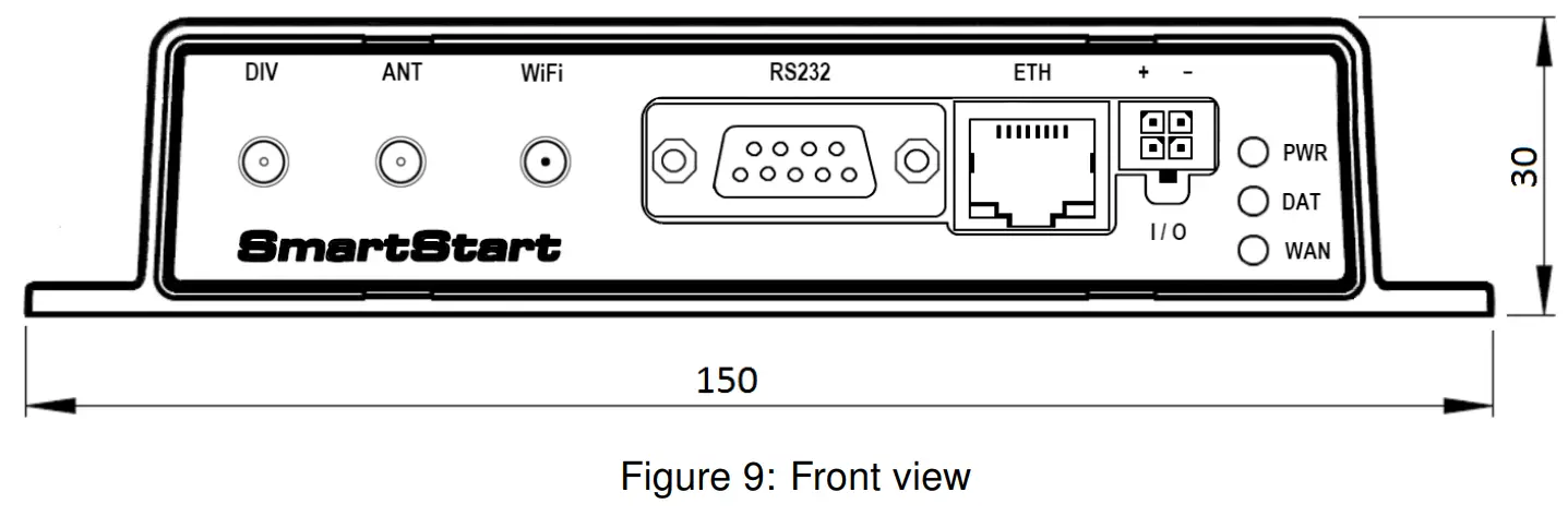
5.4 Basic Dimensions of the Router
5.4.1 Front view
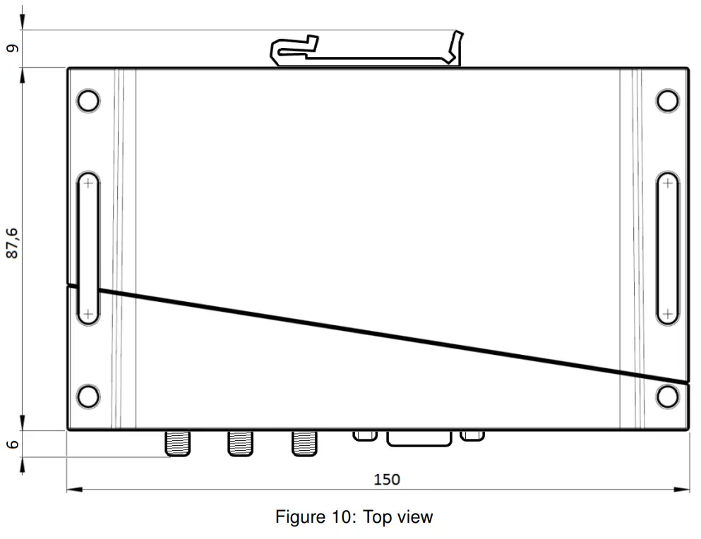
5.4.2 Top view
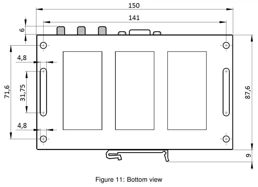
 5.4.3 Bottom view
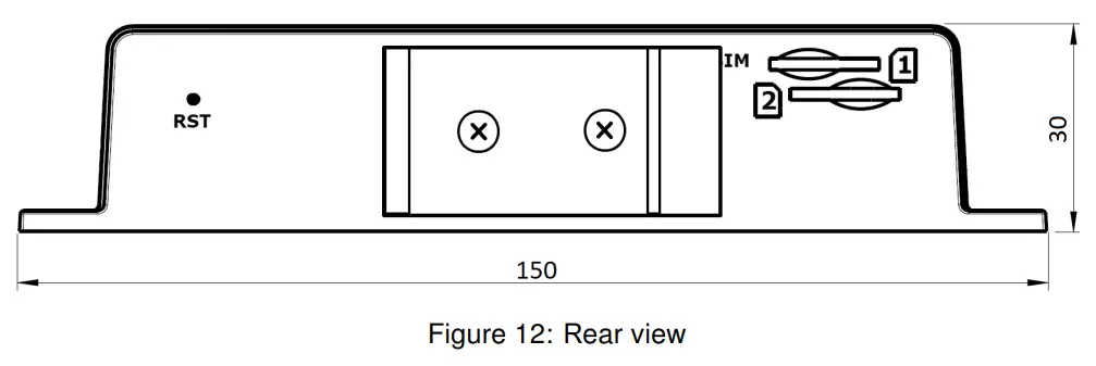
 5.4.4 Rear view
5.5 Mounting recommendations
- It is possible to place the router on a flat surface,
- mount the router on a wall using four holes in corners (Figure 11) and screws with a diameter 4 mm,
- attach the router on DIN rail EN 60715 with the included clip BB-SBD25.
The router meets EN 61439-1:2011 requirements/certifications for low-voltage switchgear and control gear assemblies. These environments are described as: - A non-public, industry environment of low voltage with high interference,
- a public environment of low voltage and without high interference.
For both of these environments, it is possible to mount the router to a switchboard, after which there is no need to have examination immunity or issues in connection with EMC according to EN 61439-1:2011.
![]() To comply with the EN 61439-1:2011 specification, follow these instructions:
To comply with the EN 61439-1:2011 specification, follow these instructions:
- For whip antennas, it is recommended to observe a minimum distance of 6 cm from cables and metal surfaces on every side in order to avoid interference. When using an
external antenna separate from the switchboard it is necessary to fit a lightning conductor. - When mounting a router on sheet steel we recommend using a cable antenna.
- For all cables, we recommend binding the bunch, and for this we recommend:
– The length of the bunch (the combination of power supply and data cables) should be a maximum 1.5 m. If the length of data cables exceeds 1.5 m or if the cable is
leading towards the switchboard, we recommend installing surge protectors.
– Data cables must not have a reticular tension of ∼ 230 V/50 Hz or ∼ 120 V/60 Hz. - Sufficient space must be left between each connector for the handling of cables,
- To ensure the correct functioning of the router we recommend the use of an earth bonding distribution frame for the grounding of the power supply of the router, data cables, and antenna within the switchboard.
![]() 5.6 Removal from the DIN rail
5.6 Removal from the DIN rail
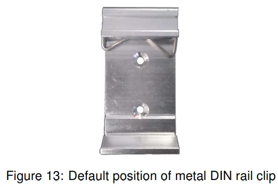
The DIN rail clip is suitable for a DIN rail according to EN 60715 standards only. The default position of the metal rail clip, which is used for mounting the router on a DIN rail, is shown in the following figure. When mounting the DIN rail clip, tighten the screws with max. 0.4 Nm torque.
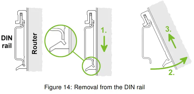
 To remove the router from the DIN rail, push the router down lightly, so the bottom part of the DIN rail clip (hitched to the DIN rail) gets out of the rail and then pull out the bottom part of the router away from the DIN rail.
5.7 Description of the Rear Panel
The rear panel contains two holders for SIM cards (SIM1, SIM2) and an RST button used to restore the default configuration followed by rebooting of the router. The picture with the rear view of the router is on figure 12. A description of the resetting procedure is described in chapter 5.8.7.
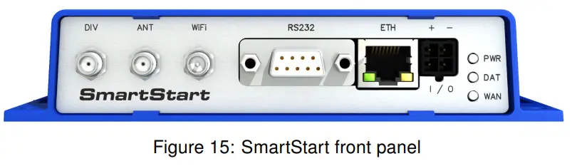
5.8 Description of the Front Panel
On the front panel is the following:
| Caption | Connector | Description |
| PWR/IO | 4-pin | Connector for the power supply and connection of the binary input and output. |
| ETH | RJ45 | Connector for connection into the computer network. |
| RS232 ANT | DB9 female | Connector for serial interface RS232. |
| DIV | SMA | Connector for main antenna. |
| WiFi | SMA | Connector for diversity antenna. |
| R-SMA | Connector for WiFi antenna (only for versions with WiFi module!). |
Table 4: Front panel description
5.8.1 Status indication
There are three LED indicators on the front panel to provide router status information. The ETH port has two additional LEDs that provide information about the port status.
| Caption | Color | State | Description |
| PWR | Green | Blinking On Fast blinking. | The router is ready. Starting of the router. Updating firmware. |
| DAT | Red | Blinking | Communication is in progress on the radio channel. |
| WAN | Yellow | Fades out 1x/5 s Fades out 1x/2 s Fades out 1x/1 s | Signal strength is good. Signal strength is fair1. Signal strength is poor2. For value ranges of signal strength see Configuration manual, chapter Mobile WAN Status. |
| ETH | Green | On Off | Selected 100 Mbps. Selected 10 Mbps. |
| ETH | Yellow | On Blinking Off | The network cable is connected. Data transmission. The network cable is not connected. |
Table 5: Status indication
![]() The status indication of the WAN LED is updated every 10 seconds.
The status indication of the WAN LED is updated every 10 seconds.
1 Or the difference between neighboring cells is exactly 3 dBm.
2 Or the difference between neighboring cells is smaller than 3 dBm.
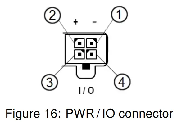
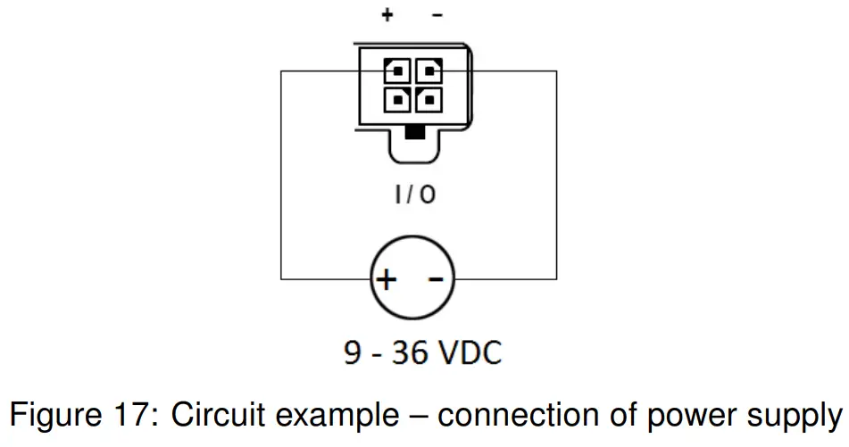
5.8.2 Power PWR/IO Connector
Panel socket 4-pin.
| Pin number | Signal mark | Description |
| 1 | GND(-) | The negative pole of DC supply voltage |
| 2 | VCC(+) | The positive pole of DC supply voltage (+9 to +36 V DC, 1 A) |
| 3 | IN0 | Binary input |
| 4 | OUT0 | Binary output |
Table 6: Connection of PWR / IO connector
![]() The unit has to be supplied by a power supply specified as a Limited Power Source (LPS) according to Annex Q of IEC 62368-1:2014. If the power supply/cable provided with the device is not used, always use the cables with a minimum wire size (nominal cross section) of 0.5 square mm for the power supply.
The unit has to be supplied by a power supply specified as a Limited Power Source (LPS) according to Annex Q of IEC 62368-1:2014. If the power supply/cable provided with the device is not used, always use the cables with a minimum wire size (nominal cross section) of 0.5 square mm for the power supply.
The power supply for the router must be between +9 V to +36 V DC, with current output 1 A. Protection against reversed polarity without signaling is built into the router. Note: The protection against reversed polarity is lost if the negative pole is grounded!![]() The router is awakened after the power supply outage and subsequent renewal.
The router is awakened after the power supply outage and subsequent renewal.
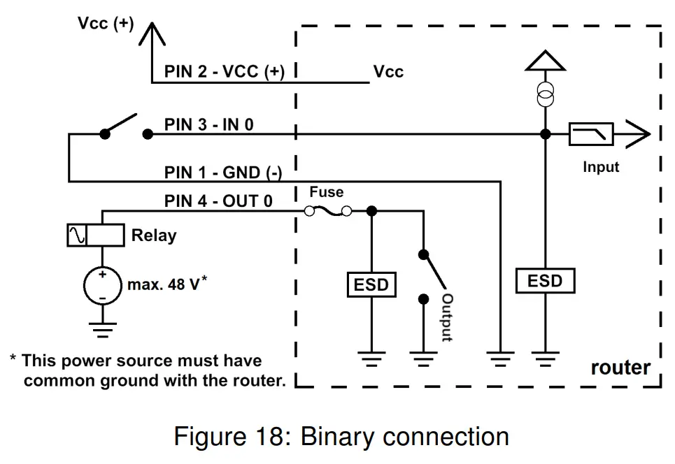
The PWR / IO interface is also designed for the processing of binary input and control (setting) of binary output.
Binary Input
| Logical 0 / 1∗ | Voltage | Web interface status |
| logic 0 | 0 – 0.7 V | On |
| logic 1 | 1.6 – 36 V | Off |
Table 7: Characteristics of binary input
∗ The binary input status in the Shell is returned via io get bin0.
Binary Output
The binary output is open in the default configuration. The current of the binary output is limited by a resettable fuse (200 mA).
Binary inputs and output connections
Binary inputs and output connections example:
Low Power Mode
The router can be put into low power mode using a special command up. It can then be awakened by activity on binary input or using an internal timer. For more details of this command, see the application note Commands and Scripts [3]. Consumption in LPM mode may vary depending on the configuration of the router.![]() All metal parts are connected together with the negative pole of the power supply (common pole).
All metal parts are connected together with the negative pole of the power supply (common pole).
However, the router box may not be connected to the negative pole properly.
5.8.3 Antenna Connector ANT, DIV, and WiFi
The main and diversity antennas are connected to the router using the SMA connector on the front panel. There is also an R-SMA antenna connector available, through which an additional antenna can be connected if the router is equipped with a WiFi module.
The ANT connector is used to First, connect the main antenna to the router. To connect the diversity antenna, the second antenna connector DIV is used. An R-SMA connector named WiFi is designed for the connection of a WiFi antenna (available only for versions with a WiFi module).
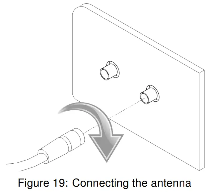
![]() The router can not operate without the main antenna connected through the port marked as ANT!
The router can not operate without the main antenna connected through the port marked as ANT!![]() An SMA connector is used for the connection of the antenna. The antenna is connected by screwing this antenna to the SMA connector on the router’s front panel (see the figure below).
An SMA connector is used for the connection of the antenna. The antenna is connected by screwing this antenna to the SMA connector on the router’s front panel (see the figure below).
Recommended tightening moment is 0.9 Nm.
![]() A diversity antenna improves the radio capability of the router at low signal strength.
A diversity antenna improves the radio capability of the router at low signal strength.
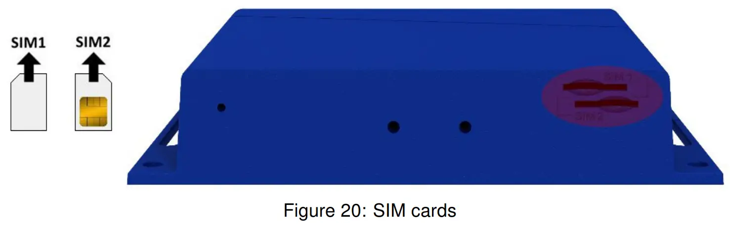
5.8.4 SIM Card Reader
The SmartStart SL302 contains two readers for 3 V and 1.8 V SIM cards, which are located on the rear panel of the device. In order for the router to function, it is necessary to insert an activated SIM card with an unblocked PIN code. The SIM cards may have different APNs (Access Point Names) adjusted.![]() Supported type of SIM cards: Mini SIM (2FF), dimensions 25.0 x 15.0 x 0.76 mm.
Supported type of SIM cards: Mini SIM (2FF), dimensions 25.0 x 15.0 x 0.76 mm.
![]() Changing the SIM card:
Changing the SIM card:
- Always disconnect the router from the power supply before handling the SIM card.
- To remove the SIM card, use the flat end of a spudger, or your fingernail, press the SIM card slightly into its slot until you hear a click.
- After hearing this click, release the card, and it will pop out of its slot.
- Remove the SIM card and push any other SIM card into the slot until it clicks into place.
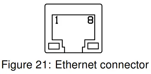
5.8.5 Ethernet Port ETH
The panel socket RJ45 is used for this interface. The isolation barrier of the Ethernet signal ports against the ground is 1500 V.
| Pin | Signal mark | Description | Data flow direction |
| 1 | TXD+ | Transmit Data – positive pole | Input/Output |
| 2 | TXD- | Transmit Data – negative pole | Input/Output |
| 3 | RXD+ | Receive Data – positive pole | Input/Output |
| 4 | — | — | |
| 5 | — | — | |
| 6 | RXD- | Receive Data – negative pole | Input/Output |
| 7 | — | — | |
| 8 | — | — |
Table 8: Connection of Ethernet connector
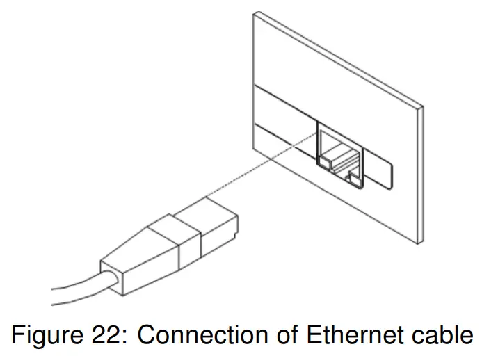
 The Ethernet cable plugs into the RJ45 connector labeled as ETH (see the figure below).
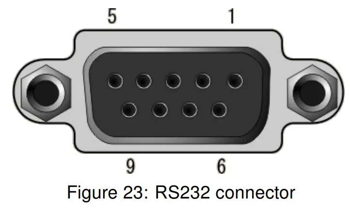
 5.8.6 Serial Port RS232
This interface is physically connected through the DB9 Female connector.
| Pin | Signal mark | Description | Data flow direction |
| 1 | DCD | Data Carrier Detect | Output |
| 2 | RXD | Receive Data | Output |
| 3 | TXD | Transmit Data | Input |
| 4 | DTR | Data Terminal Ready | Input |
| 5 | GND | System Ground | — |
| 6 | DSR | Data Set Ready | Output |
| 7 | RTS | Request to Send | Input |
| 8 | CTS | Clear to Send | Output |
| 9 | RI | Ring Indicator | NC |
Table 9: Connection of RS232 connector
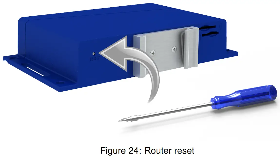
 5.8.7 Reset
When the PWR LED starts flashing on the front panel, it is possible to restore the default configuration of the router by pressing the RST button on the rear panel. After pressing this button, the default configuration will be restored and the router will reboot (after which the green LED will be on).
In order to press the RST button, it is necessary to use a narrow screwdriver or another small tool.
![]() Before resetting the router, it is recommended to back up the router configuration settings (see Configuration manual) because resetting the router will return all configuration settings to their default states.
Before resetting the router, it is recommended to back up the router configuration settings (see Configuration manual) because resetting the router will return all configuration settings to their default states.
It is important to distinguish between a router reset and a reboot.
| Action | Router behavior | Invoking events |
| Reboot | Turns off and then turns on the router | Disconnect and reconnect the power, press the Reboot button in the web configuration |
| Reset | Restores the default configuration and reboots the router | Press the RST button |
Table 10: Description of router reset and restart
First Use
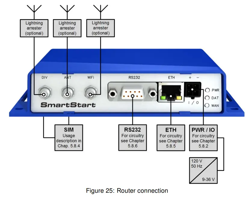
6.1 Connecting the Router Before the First Use
Before putting the router into operation it is necessary to connect all of the components that are required to run your applications. Don’t forget to insert a SIM card.
![]() The router can not operate without a connected antenna, SIM card, and power supply. If the antenna is not connected, the router may be damaged.
The router can not operate without a connected antenna, SIM card, and power supply. If the antenna is not connected, the router may be damaged.
 6.2 Start
The router will start when a power supply is connected to the router. By default, the router will automatically start to log on to the default APN. The DHCP server will start to assign addresses for devices connected through the Ethernet port ETH. The router’s behavior can be changed via the web interface. This is described in detail in the Configuration manual for SmartStart.
6.3 Configuration![]() If no SIM card is inserted in the router, it is not possible for the router to operate. Any inserted SIM card must have active data transmission.
If no SIM card is inserted in the router, it is not possible for the router to operate. Any inserted SIM card must have active data transmission.
6.3.1 Configuration by a web browser
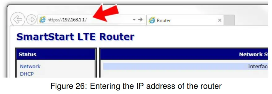
For status monitoring, configuration, and administration of the router, a web interface is available, which can be accessed by entering the IP address of the router into the web browser.
The default IP address of the router is 192.168.1.1. Attention, it is necessary to use HTTPS protocol for secure communication over a network!
 By default, configuration may be performed only by the user “root”. The default password is printed on the router’s label. 1 Change the default password as soon as possible!
![]() All routers have the WebAccess/DMP client pre-installed by default. The activated client periodically uploads router identifiers and configuration to the WebAccess/DMP server.
All routers have the WebAccess/DMP client pre-installed by default. The activated client periodically uploads router identifiers and configuration to the WebAccess/DMP server.
See the configuration manual [2], chapter Basic Information -> WebAccess/DMP Configuration, for more information.
1 If the router’s label does not contain a unique password, use the password “root”.
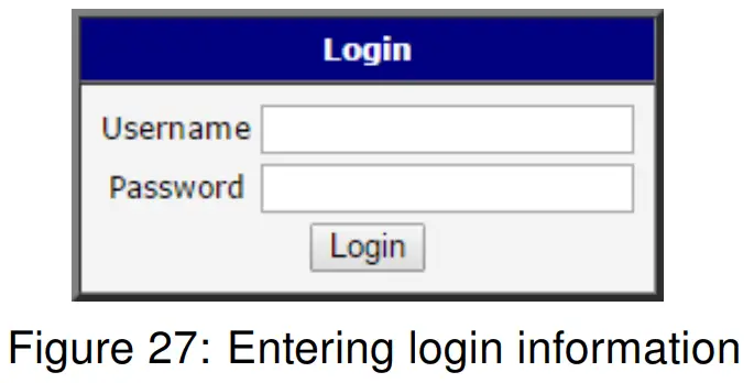 Once the login information is entered successfully, the user will have access to the router’s web interface via the web browser.
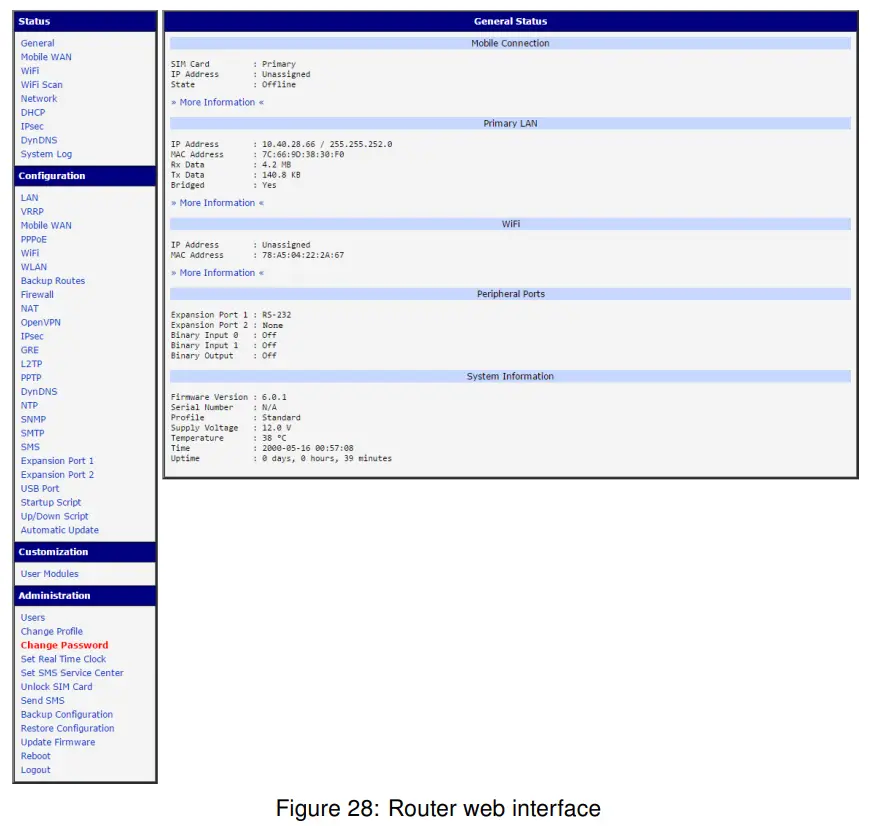
![]() A detailed description of the router settings in the Web interface can be found in the Configuration manual for SmartStart.
A detailed description of the router settings in the Web interface can be found in the Configuration manual for SmartStart.
Technical Parameters
7.1 Basic Parameters
SmartStart | ||
| Temperature range | Operating Storage | -40 ◦C to +75 ◦C (-40 ◦F to +167 ◦F) -40 ◦C to +85 ◦C (-40 ◦F to +185 ◦F) |
| Humidity | Operating Storage | 0 to 95 % relative humidity non-condensing 0 to 95 % relative humidity non condensing |
| Altitude | Operating | 2000 m / 70 kPa |
| Degree of protection | IP30 | |
| Supply voltage | 9 to 36 V DC | |
| Battery for RTC | CR1225 | |
| Consumption without WiFi | Average Maximum | 2.1 W 4.8 W |
| Consumption with WiFi | Average Maximum | 2.7 W 5.5 W |
| Sleep mode consumption | 40 mW | |
| Dimensions | 30 x 87 x 150 mm (1.18″ x 3.43″ x 5.91″) (DIN 35 mm, EN 60715) | |
| Weight | approximately 190 g (0.41 lbs) (depending on the interface) | |
| Antenna connectors | 2x SMA – 50 Ohm 1x R-SMA – 50 Ohm (only for WiFi) | |
Table 11: Basic parameters
![]() ∗ The temperature range for routers equipped with WiFi modules is reduced to -25 ◦ C to +55 ◦ C (-40 ◦ F to +131◦ F)!
∗ The temperature range for routers equipped with WiFi modules is reduced to -25 ◦ C to +55 ◦ C (-40 ◦ F to +131◦ F)!
7.2 Technical specification of user interfaces
| ETH | RS232 | |
| Connector | RJ45 | DB9 Female |
| Standard | IEEE 802.3 | |
| Min. data rate | 10 Mbps | 300 bps |
| Max. data rate | 100 Mbps | 230400 bps |
| Max. total cable length (300 Bd, 200 nF/km) | 100 m | 20 m |
Table 12: Technical specification of user interfaces
7.3 Standards and Regulations
The router complies with the following standards and regulations.
| Standards and regulations | |
| Industrial | FCC 15.107 Class B, FCC 15.109 Class B, FCC ID 2AIQR-SL302, Contains: FCC ID RI7LE910NAV2. WiFi version contains: FCC ID VRA-SG9011059B. PTC IEC 61000-6-2 |
| Safety | IEC 62368-1, EN 62311, EN 45545-2 The United States and Canada, UL File No.: E487720 For Mexico UL File No: CoC-Mex-02085-UL |
| Carrier approvals | AT&T, Verizon |
| Environmental | REACH, RoHS, and WEEE compliant |
Table 13: Standards and regulations
7.4 Type Tests and Environmental Conditions
| Phenomena | Test | Description | Test levels |
| ESD | EN 61000-4-2 | Enclosure contact Enclosure air | ± 6 kV (crit. A) ± 8 kV (crit. A) |
| RF field AM modulated | EN 61000-4-3 | Enclosure | 10 V/m (crit. A) (80 – 2700 MHz) 3 V/m (crit. A) (2700 – 6000 MHz) |
| Fast transient | EN 61000-4-4 | Power port Ethernet port RS232 port I/O port | ± 2 kV (crit. A) ± 1 kV (crit. A) ± 1 kV (crit. A) ± 1 kV (crit. A) |
| Surge | EN 61000-4-5 | Ethernet port Power port | ± 1 kV (crit. A), shielded cab. ± 0,5 kV (crit. A) |
| RF conducted | EN 61000-4-6 | All ports | 10 V/m (crit. A) (0,15 – 80 MHz) |
| Radiated emission | EN 55022 | Enclosure | Class B |
| Conducted emission | EN 55022 | DC power ports Ethernet ports | Class B Class B |
| Dry heat | EN 60068-2-2 | Operation Storage | +75 ◦C, 40 % rel. humidity, 16 hours +85 ◦C, 40 % rel. humidity, 16 hours |
| Cold | EN 60068-2-1 | Operation Storage | -40 ◦C, 16 hours -40 ◦C, 16 hours |
| Damp heat | EN 60068-2-30, test Db | +55 ◦C / +25 ◦C, 12 h – 12 h, 2 cycles | |
| Temperature variation | EN 60068-2-14 Nb | -40 ◦C / +75 ◦C, 3 h / 3 h, 2 cycles, 3 K/min | |
| Vibration | EN 60068-2-64 ed. 2 | Transport. box DIN rail direct mounting | 3 axis, 1 hour per axis 3 axis, 0.5 hours per axis 3 axis, 8 hours per axis |
| Shock | EN 60068-2-27 ed. 2 | half-sine, 15 g peak, 11 ms, 6 pulses per axis | |
| Isolation | – | Ethernet port | 1.5 kV |
Table 14: Type tests and environmental conditions
7.5 Technical Parameters of Cellular Module
| Cellular module for NAM | |
| LTE parameters | Bit rates: 10 Mbps (DL) / 5 Mbps (UL) LTE FDD Cat.1, 3GPP Release 9 compliant Supported bandwidths: 5 MHz, 10 MHz, 20 MHz Supported frequencies: B12/B13 (700 MHz), B5 (850 MHz), AWS B4 (1700 MHz), B2 (1900 MHz) |
| UMTS parameters | Bit rates: 42.2 Mbps (DL) / 5.74 Mbps (UL) Supported frequencies: B5 (850 MHz), B2 (1900 MHz) |
| Other parameters | Rx Diversity and MIMO DL 2×2 |
Table 15: Technical parameters of the cellular module
Antenna Requirements
- VSWR – <2:1 (Antenna input impedance response as a function of frequency. This shows the antenna resonances and its bandwidth).
- SMA – 50 Ω
- For good diversity performance, the primary and secondary antennas should have different polarizations.
7.6 Technical Parameters of WiFi
| WiFi | |
| Antenna connector | R-SMA – 50 Ω |
| Supported WiFi bands | 2.4 GHz |
| Standards | 802.11b, 802.11g, 802.11n |
| 2.4 GHz supported channels | 1, 2, 3, 4, 5, 6, 7, 8, 9, 10, 11 |
| RX Sensitivity | 11b, 11 Mbps: typ. -85 dBm 11g, 54 Mbps: typ. -70 dBm (HT20) 11n, MSC7: typ. -66 dBm (HT40) 11n, MSC7: typ. -62 dBm |
| TX Output Power | 11b, 11 Mbps: min. 18, typ. 19, max. 20 dBm 11g, 54 Mbps: min. 14.5, typ. 16, max. 17.5 dBm 802.11n (HT20): min. 13.5, typ. 15, max. 16.5 dBm 802.11n (HT40): min. 13.5, typ. 15, max. 16.5 dBm |
| Type of device | The access point, station |
| AP maximum users | Unlimited (WiFi module does not support multi-role operation). |
Table 16: Technical parameters of WiFi
7.7 Other Technical Parameters
| Other technical parameters | |
| CPU power | 2 DMIPS per MHz |
| Flash memory | 256 MB |
| RAM | 512 MB |
| M-RAM | 128 kB |
Table 17: Other technical parameters
- Advantech Czech: Start Guide for SmartStart,
- Advantech Czech: SmartStart Configuration Manual,
- Advantech Czech: Commands and Scripts.
Troubleshooting
If you cannot connect to the router from your PC, your network card may be configured in such a way that it is not possible to connect to the router. Take one or more of the following steps in order to solve the problem:
- Make sure your PC’s network card is configured to obtain the IP address from the DHCP server (by default the DHCP server is running in the router).
- Connect the router to the PC via Switch.
- Connect the router to the PC, start the router first and then start the PC after the router’s initialization.
9.1 FAQ
✍ Ethernet connection fails or is not established.
- It is possible to turn auto-negotiation off and set a rate and duplex manually on the Ethernet interface of the router. Available on the “LAN Configuration” page in the router.
✍ Mobile WAN connection fails.
- Check the signal power (“Mobile WAN status” page). If the signal power is weak, you will have to use a better antenna. If the neighboring cells have similar signal
strength, you will need to use a directional antenna. For proper operation, the signal levels have to be good. - Try to enable automatic ping from the router, which will check the connection when there are no data running, and in the case of a failed ping, restart the connection.
This can be done on the “Mobile WAN Configuration” page in the router in the “Check connection” section. The “Enable + bind” option is to ensure the ping goes always through the Mobile WAN network interface.
✍ Mobile WAN connection cannot be established.
- Check the “Mobile WAN Configuration” – APN, name, password, and IP address (all can be blank).
- Try to enter the SIM card PIN – verify that the SIM card has the PIN code entered.
Available on the “Unlock SIM Card” page in the “Administration” section. - In a private APN, it is not recommended to get the DNS settings from the operator (on the “Mobile WAN” page)
- Go to the “System Log” page in the “Status” section and observe where the error occurs.
✍ I cannot connect from the Internet to the device behind the router. I have NAT enabled.
- The device’s gateway has to be configured so it points to the router.
✍ I can’t access my Web server placed behind the router over NAT.
- The remote HTTP access to the router has to be disabled on the “NAT Configuration” page in the router. Also, enable the “Send all remaining incoming packets to default server” feature and fill in the IP address of your Web server. On the Web server, the default gateway has to be the IP address of the router.
✍ DynDNS doesn’t work.
- With private APN this will not work.
- If the same IP address is recorded in your canonic name as a dynamically assigned address, it means that the operator is using NAT or a firewall.
- You can verify NAT using ping to your server with a static address and then compare it with the router’s IP address.
- You can verify a Firewall by accessing remotely the router’s Web interface.
- The operator may not provide the address of the DNS server and without the DNS server’s address, it is impossible to connect to the dyndns.org server. The following essages will be shown in the System Log:
– DynDNS daemon started
– Error resolving hostname: no such file or directory
– Connect to DynDNS server failed
✍ L2TP or IPSec isn’t established.
- Check the “System Log” page for error messages.
✍ IPSec tunnel establishes but the communication does not run.
- Probably there are bad routing rules defined in the connected devices or the default gateway.
✍ I switched the router to offline mode by SMS message, but the router is in online mode after reboot.
- SMS messages do not change the router’s configuration. They remain in effect only until the router is rebooted.
✍ Serial communication is not working.
- Verify that the router model supports serial communications. Also, verify the serial communication settings. To do so, open the router’s configuration menu via the web browser, select the appropriate “Expansion Port” from the “Configuration” part of the menu and verify the settings.
✍ Is the router Cisco compatible? Can I use the Cisco configuration?
- No, the Firmware in the router (Conel OS) is based on Linux with BusyBox. Thus the Cisco configuration cannot be used. But network connections are defined by standards so connecting the router to the Cisco or other networking devices is possible and will be compatible.
✍ FTP or SFTP does not work
- FTP will work on v2 routers only. You can use SFTP on all routers to transfer files to/from the router. If having trouble with FTP on v2 routers, make sure you have
FTP enabled: “Configuration” section, “Services”, “FTP”. Then you can connect with any client on port 21 with name and password same as for the Web interface.
If having trouble with SFTP, make sure you have SSH enabled: “Configuration” section, “Services”, “SSH”. Then you can connect with any client on port 22 with a name and password same as for the Web interface.
✍ How can I connect to the router’s command line? (SSH, Telnet)
- You can use SSH on all routers or Telnet on v2 routers only. SSH is enabled by default, but you can verify in the Web interface in the “Configuration” section, “Services”, “SSH”. Then connect with any SSH client on port 22 of the router. The user and password are the same as for the Web interface. Telnet on v2 routers can be enabled here: “Configuration” section, “Services”, “Telnet”.
Customer Support
| Customer Support for Europe Advantech Czech s.r.o. Sokolska 71 562 04, Usti nad Orlici, Czech Republic Phone: +353 91 792444 Fax: +353 91 792445 E-mail: [email protected] Web: www.advantech.com | Customer Support for NAM Advantech B+B SmartWorx 707 Dayton Road Ottawa, IL 61350 USA Phone: +1-800-346-3119 (Monday – Friday, 7 a.m. to 5:30 p.m. CST) Fax: +1-815-433-5109 E-mail: [email protected] Web: www.advantech-bb.com | Customer Support for Asia Phone: +886-2-2792-7818 #1299 (Monday – Friday, 9 a.m. to 5:30 p.m. UTC+8) Fax: +886-2-2794-7327 E-mail: [email protected] Web: www.advantech.com |


