KUFATEC Touareg 7P Complete Set Active Sound incl Soundbooster
Liability Exclusion
Dear Customer
Our cable sets are developed according to the connection- and circuit diagrams of the corresponding car manufacturer. Before the original production the cable sets will be tested on an original car. Therefore, the integration into the car electronics will be executed according to the instructions of the manufacturer. Regarding the necessary pre-understanding and the accuracy of the presentation of texts and pictures our mounting guidelines correspond to the usual ones in car technology and car electronics. Practically, they have been proved one’s worth a hundred times. However, should there be any difficulties during the installation of our products we will be at your dis-posal any time for support by phone or by mail. Moreover, we offer you to execute the installation at our works in Bad Segeberg. Costs which may arise because a third person will execute the installation of our products will not be supported by us in any case. Only if there is a mistake caused by our product we will pay the proved costs of the installation as well as the costs of the removal of the defective product. The refund of expenses will be limited to gross EUR 110,- ; we reserve the right to check the described mistake in our works in Bad Segeberg. In case of a proved reclamation the costs for dispatch for the check in our factory will be transferred to you. According to our experience each specific factory which has the necessary diagnostic device, diagnostic software and the circuit diagrams of the manufacturer can find possible mistakes at our products within a short time. So the installation and removal including diagnostic inspection can be realised in at most 60 minutes. We also made the experience that many specific factories cannot work with the circuit diagrams of the manufacturer, and that they cannot read usual wiring diagrams. Therefore, very easy installation works will take many hours. You will understand that we neither take the risk to find a reliable specific factory nor the financing of the training of the staff of your favoured factory. Costs which will arise because you buy missing parts or spare parts at other suppliers will be refunded by us up to the amount of the costs which had been arisen by additional supply (saved expenses). In this case, there would be no right for refund according to the legal guarantee right as long as we have no deadline for supplementary performance or a deadline for supplementary performance has not expired. So if you have any problems with the installation or operation of one of our products please call us, send us an email, send us the product or take your car to our factory in Bad Segeberg. We are sure to find an appropriate solution for each concern. With best regards Your Kufatec GmbH & Co. KG Team
Copy Right
Our installation- and removal instructions, installation plans, software and other documentation with texts or pictures are protected by copy right. A publication or distribution of these documents is only permitted with a written approval of Kufatec GmbH & Co. KG.
General Notes
Regarding the development there has especially been paid attention to your personal safety together with the most possible operating comfort, modern design and actual product technologies. Despite most possible accuracy in case of incorrect installation or use or in case of incorrect operating, it is possible that injuries or damages of property may arise. Therefore, please read the operating instructions you have received carefully and completely, and keep it with you. All articles of our production will be checked at 100% — for your safety. We reserve the right to make technical changes which serve the progress at any time. Before the installation or startup it may be necessary, depending on the article and purpose of use, to check the legal instructions of each country. In case of warranty claim the device has to be sent to the seller originally packed together with the sales receipt and a detailed description of the mistake. Please consider the manufacturer’s instructions for return (RMA). The legal warranty instructions are valid. The warranty claim and also the permission for startup will expire in case of:
- unauthorised changes on the device or the accessories which have not been executed or approved by the manufacturer or its partners
- opening of the box
- repair of the device on your own
- incorrect use / no normal use / startup
- influence of force on the device (falling down, wilful damage, accident, etc.)
During the installation please consider all safety and legal instructions. The device may only be installed by trained qualified personnel or persons who are similar qualified.
In case of installation- or function problems please reduce the search of the mistake to approx. 0,5 hours for mechanical works or 1,0 hours for electronic works.
To avoid unnecessary additional work and expenses, please send immediately an inquiry to our technical support with the Kufatec contact form (http://www.kufatec.de/shop/de/infocenter/)
Please absolutely mention the following:
- car chassis number
- part number of the add-on kit
- exact description of the problem
- work steps already made
Safety instructions
The installation may only be executed by trained qualified personnel. Please execute the installations only in a condition of dead voltage. Here please separate for example the battery from the main power supply and consider the instructions of the car manufacturer.
- In order to not endanger your own driving safety please never use security relevant screws, bolts or other fixation pieces at steering, brake system or other components.
- Connect the device only at 12V wiring system voltage with ground connection to the autobody. This assembly is not allowed for the use in trucks or other cars with 24V wiring system voltage.
- Please avoid the installation of the device at positions where the driving safety or the functional efficiency of other subassembly integrated in the car are restricted.
- This module may only be used together with the following mentioned car types and models; the instal-lation may be executed exclusively by use of the circuit points mentioned in the assembly instructions.
- Kufatec GmbH & Co. KG does not assume liability for damages which are caused by incorrect installation, the use of inapplicable circuit points or the installation into car types and -modules which are not foreseen.
- We would like to draw your attention to the fact that the module processes the data of the MOST-protocol of the car mentioned below. Therefore, during the installation of the module it will be used a model-specific complete system which we as the manufacturer of the mentioned construction line only know partly.
- Especially in case of changes within the same model line and the same year we therefore cannot guarantee the applicability of our construction line in each case. Kufatec GmbH & Co. KG does not assume liability for the applicability of our construction line with changes made by the manufacturer.
- Kufatec GmbH & Co. KG does not assume liability that the installation of the here described com-ponent has been permitted according to the guarantee instructions of particular car manufacturers. Therefore, please consider the guidelines for installation and guarantee conditions of your car manu-facturer before installation.
- The manufacturer reserves the right to change components without giving reasons.
- Subject to errors and changes
Requirements for the determinable operation
Please use the device only in its the corresponding area. In case of unprofessional and untypical use, installation or modification the permission for operation and the warranty claim will expire.
Note
Make sure that there’s enough space at the described position. If there is no space please cancel the installation and contact our technical support. The use of a sound booster is not permitted without registration in the vehicle papers, in the area of the german StVZO. The noise emission of the vehicle is increased by this retrofit. The regulations of the StVZO must be observed. It is therefore recommended to ask for a specific registration option at the responsible TU¨ V/DEKRA office before retrofitting. Outside Germany, please observe the laws on vehicle licensing applicable in your country.
How to connect a cable to another
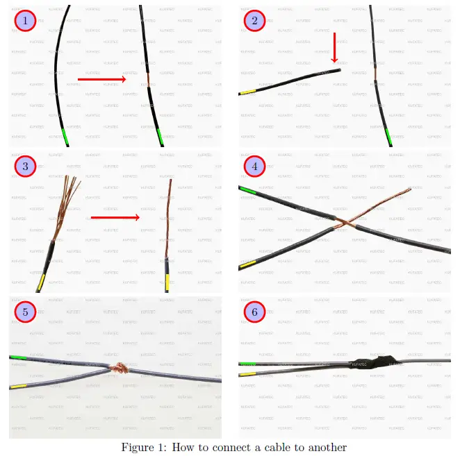
| No. | Work step | Note |
| 1 | Take the cable of the vehicle, to which you want to connect, (green marked here) and strip the insulation at one point with a suitable tool (cable stripper/cutter knife). | |
| 2 | Now take the cable of the cable set, which you want to connect, (yellow marked here) and strip the insulation at the end. | |
| 3 | Twirl the wires of the stripped cable together. | |
| 4 | Place the end of the cable you want to connect under the stripped point of the cable of the vehicle… | |
| 5 | … and wrap the cable you want to connect around the cable of the vehicle. | |
| 6 | Lastly, stick insulating tape around the connection point. |
Note Cable Inscription/Color
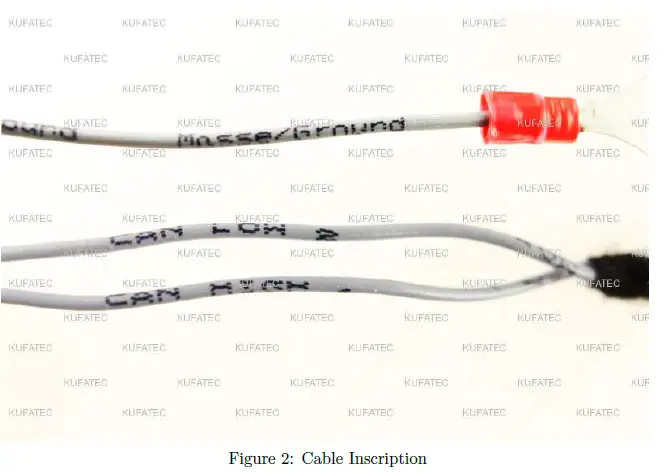
If our cable set consists exclusively of grey wires, connect the wires according to the cable inscription.
Assembly Instructions
The following illustration shows the cable routing as well as the position of the individual components.
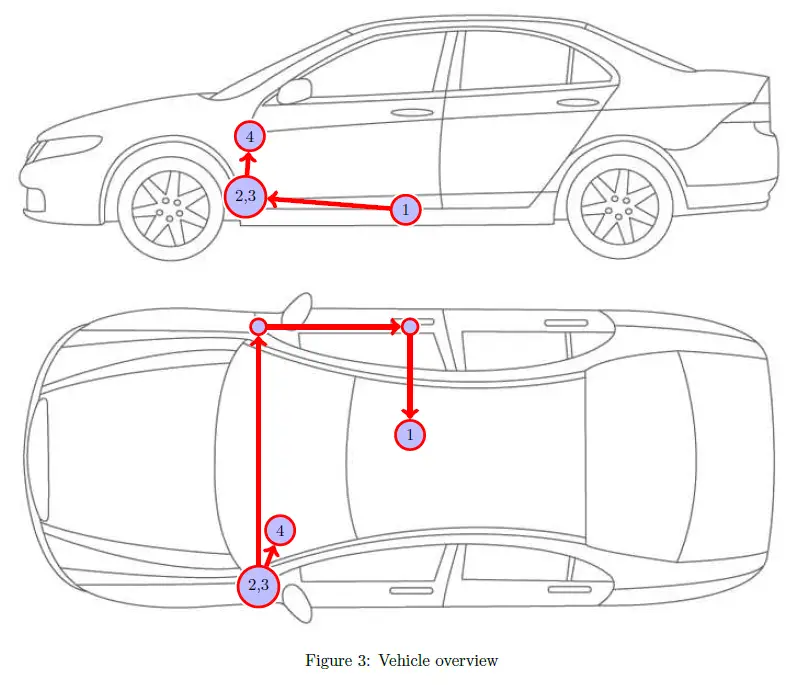
- 1External sound generator incl. mounting plate
- 2 Control unit for engine sound generation
- 3 Sound Booster Pro (module)
- 4 Pushbutton
Removing trim panel dashboard
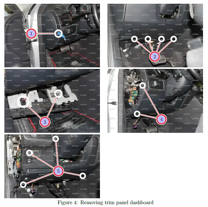
| Nr. | Work step | Note |
| 1 | Remove the lateral covering of the dashboard with a trim tool. | |
| 2 | Loosen the marked screws and pull the lower trim panel down carefully. | T20 |
| 3 | Remove the marked plugs and take the trim panel out completely. | |
| 4 | Remove the two screws of the front left trim panel of the dashboard. Afterwards it can be loosened with a trim tool and be taken out. | T20 |
| 5 | Now loosen the 4 marked screws of the front trim panel of the dashboard and afterwards remove it using a trim tool. | T20 |
Connection Ignition plus / CAN High & CAN Low
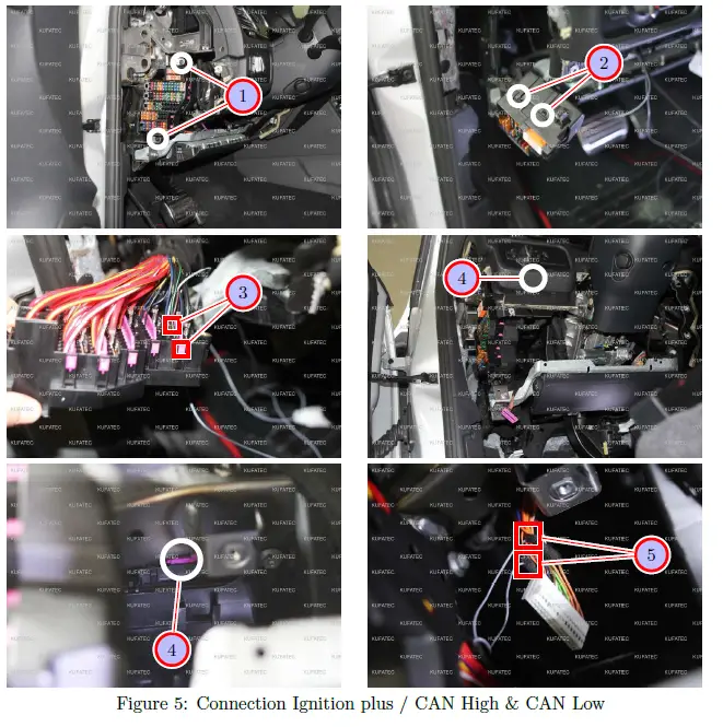
| Nr. | Work step | Note |
| 1 | Loosen the two marked screws of the fuse carrier. | T20 |
| 2 | Pull the fuse carrier forward out and remove the marked covering. | |
| 3 | Pull the rose-coloured interlock out from behind and place the cable for ignition lead (red/white) in the marked fuse spot 51. Afterwards protect the spot with a 7,5 ampere fuse. If this spot is occupied, measure with a multimeter, which fuse spot carries also ignition lead (terminal 15). | |
| 4 | Unplug the black-coloured connector with rosa locking of the CAN gateway, which is located very high up in the dashboard, and remove the plug housing. | |
| 5 | Connect CAN High and CAN Low as follows: | |
| – CAN High (black/white) to PIN 21 (orange/black colour of the cable at the plug) | ||
| – CAN Low (black/yellow) to PIN 5 (orange/brown colour of the cable at the plug) |
Connection Ground / Laying of cable
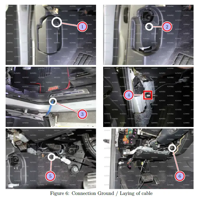
| Nr. | Work step | Note |
| 1 | Pull the interlock of the hood release out and remove it afterwards. | |
| 2 | Remove the marked screw which is located behind the hood release. | T20 |
| 3 | Loosen the sill trim on the driver’s side using a trim tool and remove it afterwards. | |
| 4 | Connect the ground cable (brown) to the ground spot, which is located directly under the hood release. | |
| 5 | Now connect the delivered control unit as well as the sound module to the cable set and place them behind the carpet of the footrest on the driver’s side. | |
| 6 | Afterwards pull the connecting cable for the external sound generator, with a pull through aid, over the knee airbag and behind the center console to the glove com- partment. |
Routing connecting cable external sound generator
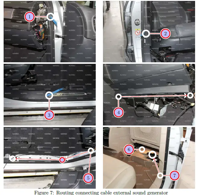
| Nr. | Work step | Note |
| 1 | Remove the upper trim panel of the a-pillar with a trim tool. | |
| 2 | Loosen the trim panel of the b-pillar with a trim tool. | |
| 3 | Now loosen and remove the sill trim with a trim tool. | |
| 4 | Please route the connection cable underneath the glove compartment into the direc- tion of the a-pillar. Stow the cable under the carpet of the footwell at passenger’s side. | |
| 5 | Afterwards the connection cable is laid along the door sill trim until the b-pillar, coming from the a-pillar. | |
| 6 | Now please lift up the carpet, then you can see the rubber grommet underneath the seat at passenger’s side. | |
| 7 | Following route the connection cable under the carpet from the b-pillar along to the marked rubber grommet, this one is positioned underneath the seat at passenger’s side. Guide the cable from the interior to the underbody. Be sure, that the rubber grommet is sealed watertight. |
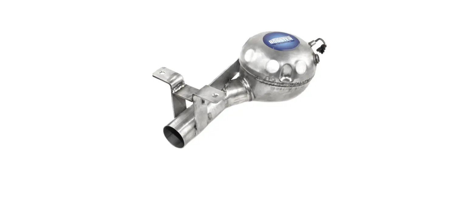
Installation external sound generator Version 1 – 4.2 TDI
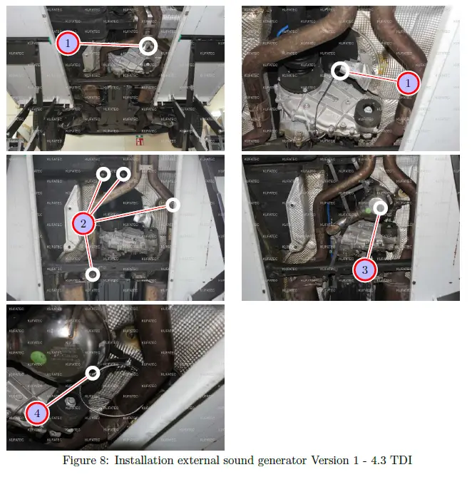
| Nr. | Work step | Note |
| 1 | Pull the connecting cable for the external sound generator further through. | |
| 2 | Loosen the marked screws at the underbody. | 13er/17er socket |
| 3 | Now install the external sound generator with the just loosened screws. | |
| 4 | Attach the safety rope to the external sound generator as well as to the vehicle. |
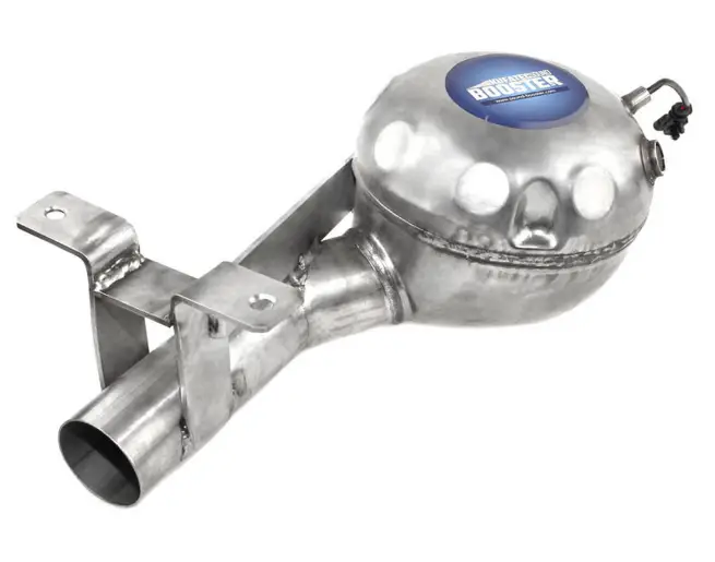
Installation external sound generator Version 2 – 3.0 TDI
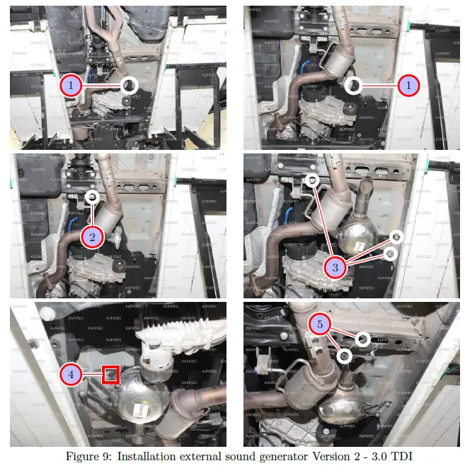
| Nr. | Work step | Note |
| 1 | Pull the connecting cable for the external sound generator further through. | |
| 2 | Loosen the marked screw at the underbody. | 1x17er socket |
| 3 | Now install the external sound generator with the just loosened screw and 2 addi- tionally screws (not included in the scope of delivery). | 1x17er socket, 2x13er socket |
| 4 | Plug in the connection cable into the external sound generator. | |
| 5 | Attach the safety rope to the external sound generator as well as to the vehicle. |
Installation external sound generator Version 3 – Gasoline Engines
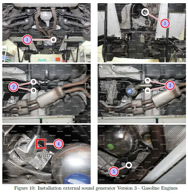
| Nr. | Work step | Note |
| 1 | Pull the connecting cable for the external sound generator further through. | |
| 2 | Loosen the marked screw at the underbody. | 2x17er socket |
| 3 | Now install the external sound generator with the just loosened screw. | 2x17er socket |
| 4 | Plug in the connection cable into the external sound generator. | |
| 5 | Attach the safety rope to the external sound generator as well as to the vehicle. |
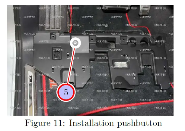
| Nr. | Work step | Note |
| 1 | Finally drill a hole for the pushbutton at the lower covering of the dashboard on the driver’s side and install the pushbutton afterwards. | 7mm |
Software
| Nr. | Work step | Note |
| 1 | If the system does not work after you have installed everything, please check by having a look on to the following Link: https://www.sound-booster.com/en/ debugging.html if everything is correct as described. For the further commissioning or debugging, our Sound Booster Software for PC / Mac should be used: | |
| Step 1: Download the appropriate software via the following link: https://www. sound-booster.com. | ||
| Step 2: Turn the ignition of the vehicle on and only then connect the PC / Mac with a USB-cable with our module. It is important here to make sure previously that plus and minus are connected correctly. If this is not the case, a damage at the computer or at the control unit can result. | ||
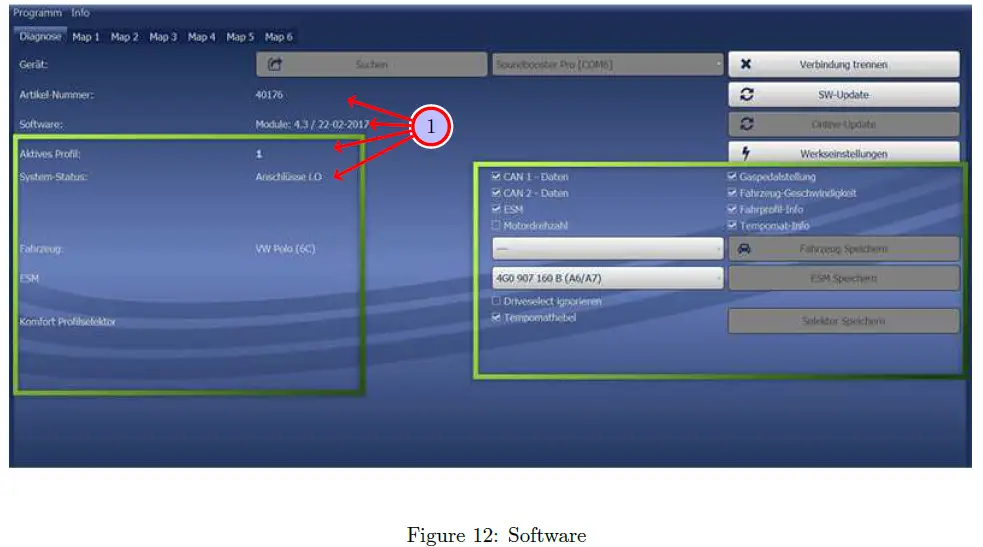
| Step 3: Start the downloaded software and first click on search and afterwards on connect. | ||
| You will be forwarded automatically to the diagnosis side, on which you can see the following things at a glance: | ||
| Software: Software version / creation date | ||
| Active profile: The actually activated profile is indicated here. | ||
| Vehicle: The automatically identified vehicle is indicated here. | ||
| System Status: You can see here, if the connections are correct. |
| Nr. | Work step | Note |
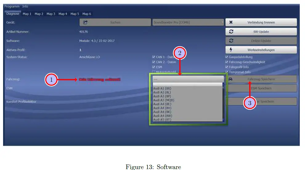
| 1 | If no current vehicle is identified, you have to select the vehicle via the Manual Selection as follows: | |
| 2 | Open the dropdown-menu, search for your vehicle and select it. | |
| 3 | Click on Save Car to save the vehicle on the module permanently. | |
| If you don’t find your vehicle in this list, it is possibly necessary that the software has to be adapted to your vehicle. For this, please contact us via e-mail: [email protected] or by phone: +49 (0) 4551 / 80 810 888. We will make an appointment with you, at which we will adapt the software to your vehicle per Team Viewer (telemaintenance). |
| Nr. | Work step | Note |
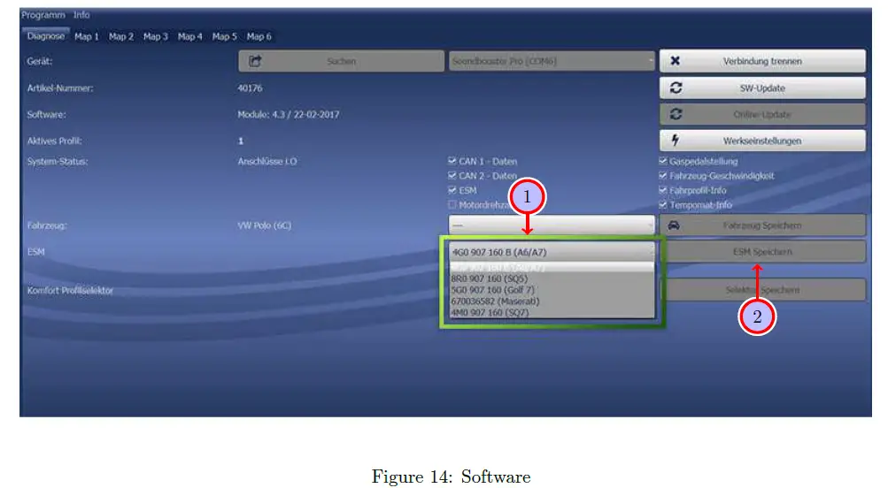
| 1 | You also need to check if the right ESM is selected in our software: | |
| Open the dropdown-menu, search for the correct ESM and select it. | ||
| 2 | Click on Save ESM to save the ESM on the module permanently. | |
| 3 | If you, for example, has ordered a complete set with Audi control unit you need to choose as ESM 4G0 907 160 B (A6/A7. If you install the Maserati Control unit you need to choose the ESM 670036582 (Maserati) | |
| If the system does not work after all please get in contact with us via e-mail: [email protected] or by phone: +49 (0) 4551 / 80 810 888. We will check the is- sue as soon as possible. |
Important Information Sound Booster
Please use for the fixation of the Sound Booster suitable high tensile screws. In order to avoid losening of the screws by vibration please make the screws safe with appropriate factory material e.g Threadlock. Please additionally check the stability of the Sound Booster regularly and if necessary retighten the screws. In case of no consideration we do not assume liability for possible damages. After successful installation we recommend to cover the sound generator with a zinc spray. Make sure that you cover the opening of the sound generator so that no zinc spray can’t get inside the sound generator. As additional safety the delivered steel cable and the retaining clips have to be tightened on the Sound Booster as well as at a suitable position in the car. This safety cable is an additional security should the tightening screws should be released by vibration.


