![]()
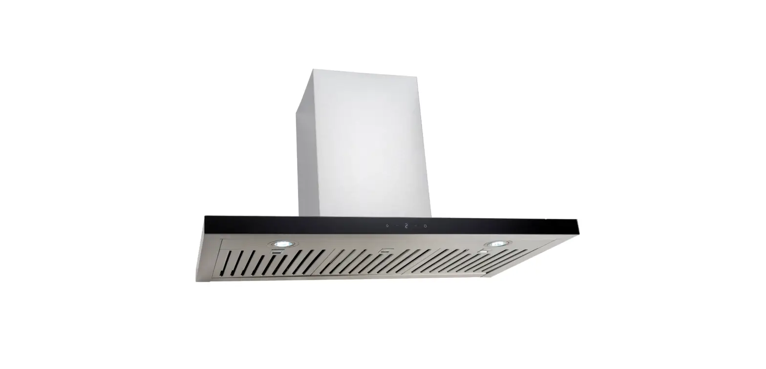
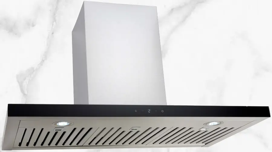
rangehoods
USAGE AND
CARE GUIDE
PRODUCT
CODE:
EMT60CS/
EMT90CS
EM60TCSX/
EM90TCSX
RECOMMENDATIONS AND SUGGESTIONS
![]() The instructions for Use apply to several versions of this appliance. Accordingly, you may find descriptions of individual features that do not apply to your specific appliance.
The instructions for Use apply to several versions of this appliance. Accordingly, you may find descriptions of individual features that do not apply to your specific appliance.
INSTALLATION
- The manufacturer will not be held liable for any damages resulting from incorrect or improper installation.
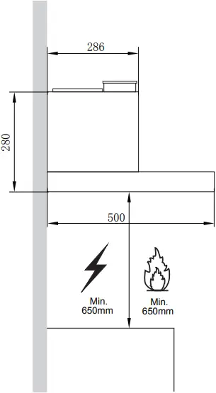
- The minimum distance between the supporting surface for the cooking vessels on the hob and the lowest part of the range hood. (When the range hood is located above a gas appliance, this distance shall be at least 65 cm. If the instructions for installation for the gas hob specify a greater distance, this has to be taken into account.
- The distance of 65 cm can be reduced for:non-combustible parts of range hoods, and parts operating at safety extra low voltage,Provided these parts do not give access to live parts if deformed;) Check that the mains voltage corresponds to that indicated on the rating plate fixed to the hood.
- For Class I appliances,check that the domestic power supply guarantees adequate earthing. Connect the extractor to the exhaust flue through a pipe of minimum diameter 120mm. The route of the flue must be as short as possible.
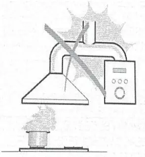
- The air must not be discharged into a flue that is used for exhausting fumes from appliances burning gas or other fuels.
- If the extractor is used in conjunction with non-electrical appliances (e.g. gas burning appliances),a sufficient degree of aeration must be guaranteed in the room in order to prevent the backflow of exhaust gas. The kitchen must have an opening communicating directly with the open air in order to guarantee the entry of clean air.
- When the cooker hood is used in conjunction with appliances supplied with energy other than electric, the negative pressure in the room must not exceed 0,04 mbar to prevent fumes being drawn back into the room by the cooker hood.
- If the supply cord is damaged, it must be replaced by the manufacturer, its service agent or similarly qualified persons in order to avoid a hazard.
- Regulations concerning the discharge of air have to be fulfilled.
- The air must not be discharged into a flue that is used for exhausting fumes from appliances burning gas or other fuels.
USE
- The cooker hood is only for home use, not suitable for barbecue, roast shop and other commercial purposes. Never use the hood for purposes other than for which it has been designed.
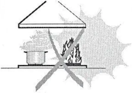
- Never leave high naked flames under the hood when it is in operation.
- Adjust the flame intensity to direct it onto the bottom of the pan only, making sure that it does not engulf the sides.
- Deep fat fryers must be continuously monitored during use: overheated oil can burst into flames.
- Do not flame under the range hood; risk of fire.
- This appliance is not intended for use by persons (including children) with reduced physical, sensory or mental capabilities, or lack of experience and knowledge, unless they have been given supervision or instruction concerning use of the appliance by a person responsible for their safety.
- Children should be supervised to ensure that they do not play with the appliance.
- Cleaning and user maintenance shall not be made by children.
- “CAUTION: Accessible parts may become hot when used with cooking appliances”.
- Do not flambe under the rangehood. There should be adequate ventilation of the room when the rangehood is used at the same time as appliances burning gas or other fuels.
MAINTENANCE
- The cooker hood and its filter should be cleaned regularly according to the instruction.
- Switch off or unplug the appliance from the mains supply before carrying out any maintenance work.
- Clean and/or replace the filters after the specified period (fire hazard).
- Clean the hood using a damp cloth and a neutral liquid detergent. The appliance uses 4 hob elements at most.
The symbol ![]() is packaging indicates that this product may not be treated as household waste. Instead it shall be handed over to the applicable collection point for the recycling of electrical and electronic equipment. By ensuring this product is disposed of correctly, you will help prevent potential negative consequences for the environment and human health, which could otherwise be caused by inappropriate waste handling of this product. For more detailed information about recycling of this product, please contact your local city office, your household waste disposal service or the shop where you purchased the product.
is packaging indicates that this product may not be treated as household waste. Instead it shall be handed over to the applicable collection point for the recycling of electrical and electronic equipment. By ensuring this product is disposed of correctly, you will help prevent potential negative consequences for the environment and human health, which could otherwise be caused by inappropriate waste handling of this product. For more detailed information about recycling of this product, please contact your local city office, your household waste disposal service or the shop where you purchased the product.
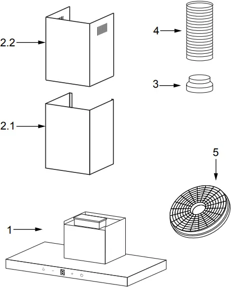
COMPONENTS
| Ref. | Qty. | Product Components |
| 1 | 1 | Hood Body, complete with: Controls, Light, Blower, Filter. |
| 2.1 | 1 | Lower Decorative Chimney |
| 2.2 | 1 | Upper Decorative Chimney |
| 3 | 1 | Flange (optional) |
| 4 | 1 | Exhaust Pipe |
| 5 | 2 | The Activated Charcoal filter (optional) |
| Qty. | Documentation |
| 1 | Instruction Manual |
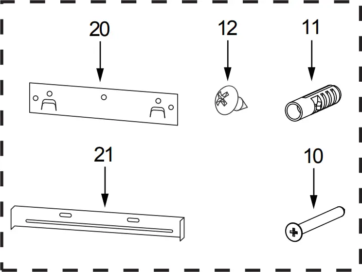
| Ref. | Qty. | Optional Installation Components |
| 10 | 7 | Screws 5 x 50 |
| 11 | 7 | Wall Plugs |
| 12 | 6 | Screws 4,2 x 9,5 |
| 20 | 1 | Hood fixing bracket |
| 21 | 2 | Chimney fixing bracket |
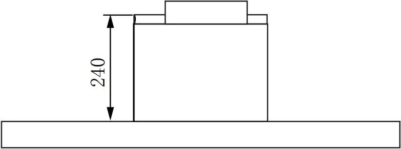
DIMENSIONS
unit: mm
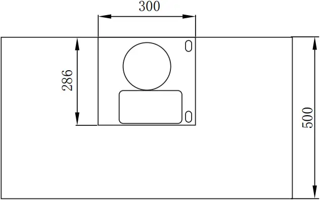
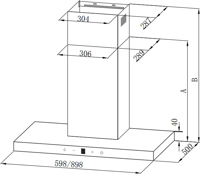
Option | Chimney | A | B | Height |
1 | 400+ | 430 | 465-800 | 430-800 |
2 | 500+490 | 530 | 565-1000 | 530-1000 |
3 | 600+590 | 630 | 665-1200 | 630-1200 |
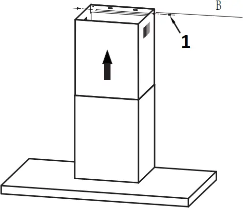
INSTALLATION
WALL DRILLING AND BRACKET FIXING
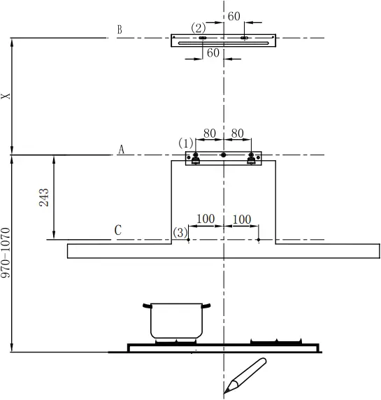
Vertical reference line
Option | Chimney | X |
| 1 | 400X390 | 160-500 |
2 | 500X490 | 260-700 |
| 3 | 600X590 | 360-900 |
A horizontal line A at 970 – 1070 mm above the cooker top.
A horizontal line B at a X mm above the horizontal line A.
A horizontal line C at a 243 mm below the horizontal line A.
As a first step, proceed with the following drawings:
- A vertical line up to the ceiling or up to the upper limit, at the center of the area in which the hood is to be fitted.
- A horizontal line A at 970 – 1070mm above the cooker top
- A horizontal line B at a X mm above the horizontal line A
- A horizontal line C at a 243mm below the horizontal line A
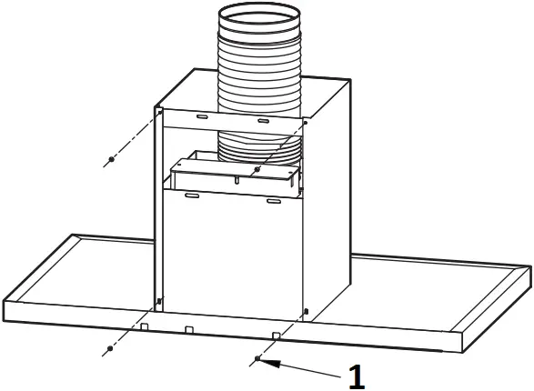
Mark Points:
- Mark a point (1) on the horizontal line A, 80 mm to the vertical reference line.
Repeat this operation on the other side and on the vertical reference line, checking that the three marks are leveled. - Mark a point (2) on the horizontal line B, 60 mm to the vertical reference line.
Repeat this operation on the other side, checking that the two marks are on the same horizontal line. - Mark a point (3) on the horizontal line C, 100 mm to the vertical reference line .
Repeat this operation on the other side, checking that the two marks are leveled.
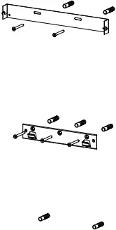
Fix the brackets:
- Drill holes at the marked points with a ɸ10 mm drill bit.
- Insert the Wall Plugs 11 into the holes.
- Fix the hood fixing bracket 20 with 3 screws 10 (5 x 50) at the horizontal line A.
Fix a Chimney fixing bracket 21 with 2 screws 10 (5 x 50) at the horizontal line B.
Lower decorative chimney
- Fix the exhaust pipe on the hood body, connect chimney and hood body with 2 screws 12. connect chimney fixing bracket and chimney with 2 screws 12.
- 4 X Screws (ST4.2*9.5)
Hook the hood body
- Hook the hood body to the bracket 20.
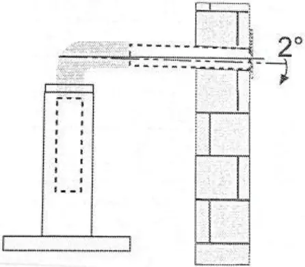
- Level the hood body itself.
- Remove the filter from the inside of the hood body, fix the screws 10 to Wall Plugs 11 at the points (3).
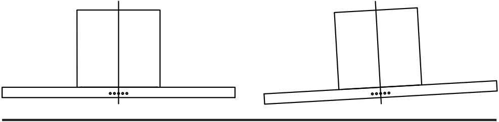
Right Wrong
CONNECTIONS
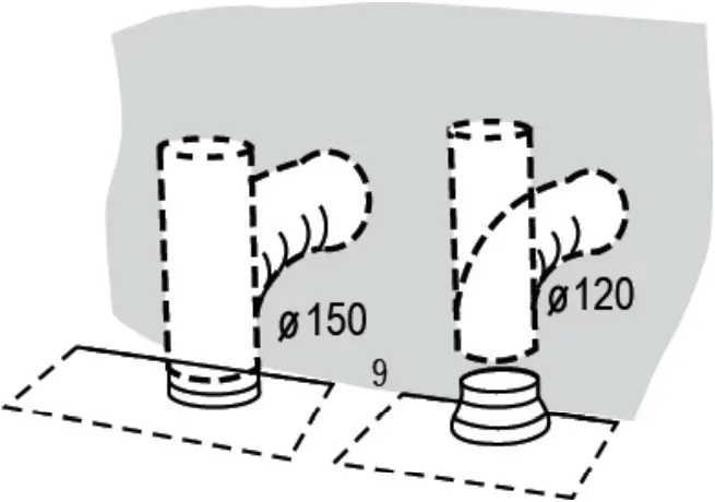
DUCTED VERSION AIR EXHAUST SYSTEM
When installing the ducted version, connect the hood to the chimney using either a flexible or rigid pipe ɸ 150 or ɸ 120 mm, the choice of which is left to the installer.
- If to install a ɸ 120 mm air exhaust connection, insert the reducer flange 3 on the hood body outlet.
- Fix the pipe 4 in position using sufficient pipe clamps (not supplied).
- Remove possible charcoal filters.
Upper Decorative Chimney
- Insert the upper decorative chimney 2.2 into the lower decorative chimney 2.1 and drag it up to the horizontal line B
- Connect upper decorative chimney 2.2 and chimney fixing bracket 21 with 2 screws 12.
- 2 X Screws (ST4.2*9.5)
USE
Speed adjustment. (For some models)
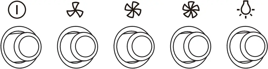
 | OFF MOTOR SWITCH: Press on this switch to stop the motor operation. |
 | SPEED SWITCH: Press on this switch, the motor runs at LOW speed. |
 | SPEED SWITCH: Press on this switch, the motor runs at MEDIUM speed. |
 | SPEED SWITCH: Press on this switch, the motor runs at HIGH speed. |
 | ON/OFF LIGHTING SWITCH: Press on this switch to turn on the lights, and press again to turn them off. |
Speed adjustment. (For some models)
After the hood is switched on, a beep sound heard and all key lights are lightened for 1 s, indicating the hood has been powered on. Under the condition the hood power-on:
- Power Key: control the motor power, under standby state, press the “power” button, “power” key light is on, the motor starts up at low speed, digital screen displays setting 1; under power-on state, press the “power” button, enter 3-min-delay-shutdown state, setting switched to low speed, the power key flashes at one second interval, which means entering delay-shutdown state; under delay-shutdown state, press the “power” button, it’s shut down immediately (motor stops running).
- Light Key: independently control the light on and off free from the effect of other keys. Press it once, the light is on, meanwhile the light key light is on; press again, the light is off and light key light is off too.
- Plus (+) Key: valid under power-on state, press plus (+) key once, motor speed increased one setting, digital tube displays corresponding setting. When the plus (+) key is pressed down, plus (+) key light is on. When at the highest setting, only give out key touch sound, the setting no longer changes.
- Minus (-) Key: valid under power-on state, press “minus (-)” key once,motor speed decreased one setting, digital tube displays corresponding setting. When the “minus (-)”key is pressed down, “minus (-)”key light is on. When at the lowest setting, only give out key touch sound, the setting no longer changes.
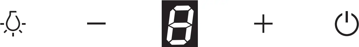
Light Minus Digital screen Plus Power
MAINTENANCE
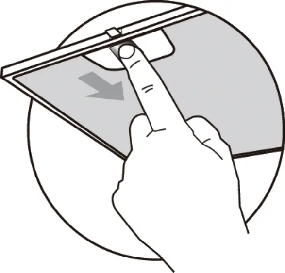
GREASE FILTERS
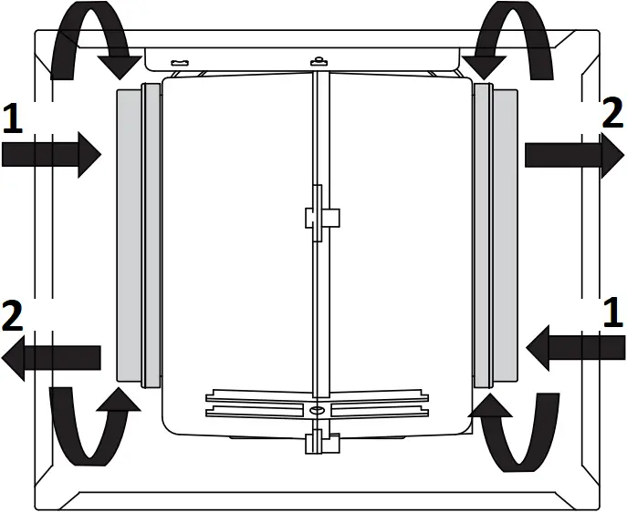
CLEANING METAL SELF-SUPPORTING GREASE FILTERS
- The filters must be cleaned every 2 months of operation, or more frequently for particularly heavy usage, and can be washed in a dishwasher.
- Remove the filters one by one pushing them towards the back side of the hood unit and simultaneously pulling downwards.
- Any kind of bending of the filters has to be avoided when washing them. Before fitting them again into the hood make sure that they are completely dry. (The color of the filter surface may change throughout the time but this has no influence to the filter efficiency). When fitting the filters into the hood pay attention that they are mounted in correct position the handle facing outwards.
ACTIVATED CHARCOAL FILTER (RECIRCULATION VERSION)
These filters are not washable and cannot be regenerated, and must be replaced approximately every 4 months of operation, or more frequently with heavy usage.
REPLACING THE ACTIVATED CHARCOAL FILTER
- Remove the metal grease filters.
- Remove the saturated activated charcoal filter.
Fit the new filters. - Replace the metal grease filters.
- FIX
- REMOVE
LIGHTING
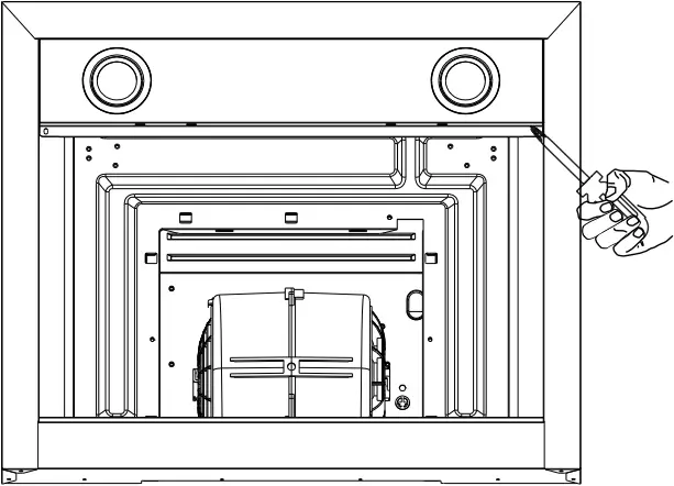
LIGHT REPLACEMENT (Completed by professionals)
Replacing the light modules
Cannot replaced the light bulbs, the entire light module has to be replaced.
When changing the light modules, the contacts are live.
Before changing the light module(s), unplug the appliance from the mains or switch off the circuit breaker in the fuse box.
- Remove the grease filter and carefully remove the 2 screws from the front plate (a cross headed screwdriver will be needed to remove the screws).
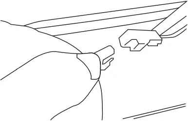
- Disconnect the terminal of LED light.
- Press LED light on the back of the front plate, take the LED light out.
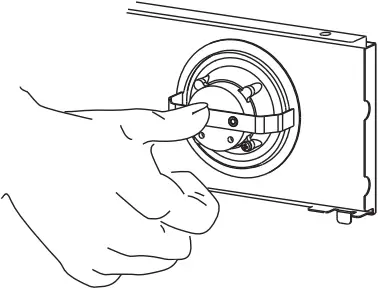
- Replace the lamp(commercially available LED lamp (max.1.5w).
Round lamp
Max Power | Voltage | Picture | Lamp Cap | ILCOS D code | |
| Round/ Diameter : 70mm | 1.5W | DC 12 V |  | —— | DSR-1.5-S-70 |
- Press LED light on the front of front plate, install the LED light on the front plate.
Connect the terminal of LED light and light leads. - Carefully fasten the 2 screws on the front plate ,reinstall the grease filter.
DISPOSAL OF OLD ELECTRICAL APPLIANCES
 The European directive 2012/19/EU on Waste Electrical and Electronic Equipment (WEEE), requires that old household electrical appliances must not be disposed of in the normal unsorted municipal waste stream. Old appliances must be collected separately in order to optimize the recovery and recycling of the materials they contain, and reduce the impact on human health and the environment. The crossed out “wheeled bin” symbol on the product reminds you of your obligation, that when you dispose of the appliance, it must be separately collected.
Consumers should contact their local authority or retailer for information concerning the correct disposal of their old appliance.
TROUBLE SHOOTING
| Fault | Cause | Solution |
| Light on, but motor does not work | The blades are blocked. | Check the blades. |
| The capacitor is damaged. | Replace capacitor. | |
| The motor is damaged. | Replace motor. | |
| The internal wiring of motor is cut off/ disconnected. An unpleasant smell may be produced. | Replace motor. | |
| Both light and motor do not work | Apart from the above mentioned, check the following: | |
| Light damaged. | Replace lights. | |
| Power cord loose. | Connect the wires as the electric diagram. | |
| Oil leakage | Outlet and the air ventilation entrance are not tightly sealed. | Take down the outlet and seal with glue. |
| Vibration | The blade, if damaged, can cause vibrating. | Replace the blade. |
| The motor is not tightly fastened. | Fasten the motor tightly. | |
| The cooker hood is not tightly fixed. | Fixed the cooker hood tightly. | |
| Insufficient suction | The distance between the cooker hood and the cooker top is too large. | Readjust the distance. |
| Too much ventilation from open doors or windows. | Choose a new place to install the appliance or close some doors / windows. | |
| The machine inclines | The fixing screws are not tight enough. | Tighten the fixing screw and make it horizontal. |
| The hanging screws are not tight enough | Tighten the hanging screw and make it horizontal. | |
![]()
Pronto Service + Support: 1800 440 335
Email: [email protected]
HEAD OFFICE
65 Glynburn Road, Glynde SA 5070
Ph: 08 8165 1012
 User Manual")


