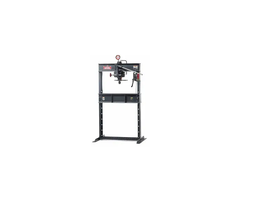
DAKE 25H Hand-Operated Hydraulic Press Instruction Manual


 Read and understand all instructions and responsibilities before operating. Failure to follow safety instructions and labels could result in serious injury.
DAKE STANDARD LIMITED WARRANTY
Finished Machines
Dake warrants to the original purchaser the finished machine manufactured or distributed by it to be free from defects in material and workmanship under normal use and service within 1 year (12 months) from the delivery date to the end user.
Parts
Dake warrants to the original purchaser the component part manufactured or distributed by it to be free from defects in material and workmanship under normal use and service within 30 days from the delivery date to the end user. The standard limited warranty includes the replacement of the defective component part at no cost to the end user.
Sale of Service (Repairs)
Dake warrants to the original purchaser the component part repaired by Dake Corporation at the manufacturing facility to be free from defects in material and workmanship under normal use and service within 90 days from the return date to the end user, as it pertains to the repair work completed. The standard limited warranty includes repair of the defective component part, at no cost to the end user.
Warranty Process
Subject to the conditions hereinafter set forth, the manufacturer will repair or replace any portion of the product that proves defective in materials or workmanship. The manufacturer retains the sole right and option, after inspection, to determine whether to repair or replace defective equipment, parts or components. The manufacturer will assume ownership of any defective parts replaced under this warranty.
All requested warranty claims must be communicated to the distributor or representative responsible for the sale. Once communication has been initiated, Dake Customer Service must be contacted for approval:
Phone: (800) 937-3253
Email: [email protected]
When contacting Dake, please have the following information readily available: – Model # – Serial # – Sales Order #
Purchasers who notify Dake within the warranty period will be issued a Case number and/or a Return Material Authorization (RMA) number. If the item is to be returned per Dake’s request, the RMA number must be clearly written on the exterior packaging. Any item shipped to Dake without an RMA will not be processed.
Warranty Exceptions:
The following conditions are not applicable to the standard limited warranty:
(a) Part installation or machine service was not completed by a certified professional, and is not in accordance with applicable local codes, ordinances and good trade practices.
(b) Defects or malfunctions resulting from improper installation or failure to operate or maintain the unit in accordance with the printed instructions provided.
(c) Defects or malfunctions resulting from abuse, accident, neglect or damage outside of prepaid freight terms.
(d) Normal maintenance service or preventative maintenance, and the parts used in connection with such service.
(e) Units and parts which have been altered or repaired, other than by the manufacturer or as specifically authorized by the manufacturer.
(f) Alterations made to the machine that were not previously approved by the manufacturer, or that are used for purposes other than the original design of the machine.
RETURN & REFUND POLICY
Thank you for purchasing from Dake! If you are not entirely satisfied with your purchase, we are here to help.
Returns
All Dake manufactured / distributed machines, parts and couplings include a 30-day return option. These policies are valid from the date of final shipment to the end user.
To be eligible for a return, the item must be unused and in the same condition as received.
All requested warranty claims must be communicated to the distributor or representative responsible for the sale. Once communication has been initiated, Dake Customer Service must be contacted for approval:
Phone: (800) 937-3253 Email: [email protected]
Once the return request has been approved by Customer Service, a representative will supply a Return Material Authorization (RMA) number. The returned item must have the provided RMA number clearly marked on the outside packaging. Any item received without an RMA number clearly visible on the packaging will not be processed. An RMA number can only be provided by the Dake Customer Service team and must be obtained prior to the return shipment.
Refunds
Once the item has been received and inspected for damages, a representative will notify the requestor referencing the provided RMA number.
If the return is approved, a refund will be issued to the original method of payment, less a 20% restocking fee. The restocking fee may be waived if an order is placed at the time of return with like-value merchandise.
Transportation costs are the responsibility of the end user and will not be credited upon return approval.
Any item that is returned after the initial 30 days or has excessive/obvious use will not be considered for a full refund.
SAFEGUARDING THE POINT OF OPERATION
ANSI B11.2 – Hydraulic Power Presses –
Safety Requirements for Construction, Care, and Use
and use of their Dake hydraulic press, including point-of-operation safe guards. Dake strongly recommends that Dake press users obtain a copy of the current American National Standard Institute (ANSI) B11.2 standard, for a more complete understanding of their responsibilities.
ANSI B11.2 states the following, relative to point of operation safeguarding:
“Normally, only the employer (press user) can determine the requirements of the press productions system components, including the dies and methods for feeding. Therefore, the employer is ultimately responsible to designate and provide the point-of-operation safeguarding system.”
The standard also discusses additional responsibilities of the employer. Some of the key responsibilities are:
- The employer is responsible for the safety, use, and care of the hydraulic power press production system.
- The employer is responsible to consider the sources of hazards for all tasks to be implemented on the hydraulic power press production system.
- The employer is required to eliminate or control identified hazards in the scope of their work activity.
- The employer is responsible for the training of personnel, caring for, inspecting, maintaining, and operating hydraulic press production systems to ensure their competence.
- The employer is responsible to provide and ensure that point-of-operation safeguarding is used, checked, maintained, and where applicable, adjusted on every production operation performed on a press production system.
SPECIFICATIONS
| Number | 907001 | Ram travel | 5” | |
| Capacity | 25 tons | Screw travel | 5” | |
| Width between uprights | 33-1/2” | Height | 76” | |
| Width between table channels | 5 -3/16” | Weight | 460 lbs | |
| Min ram to table | 4” | Base | 42-1/2” x 30” | |
| Max ram to table | 39” | |||
In the space provided record the serial number and model number of the machine. This information is only found on the black and gold Dake tag shown below. If contacting Dake this information must be provided to assist in identifying the specific machine.
| Serial No. | |
| Model No. | |
| Install Date: |

 SAFETY
Employer is responsible to perform a hazard/PPE assessment before work activity.
Follow recommended precautions and safe operating practices.
Additional Warnings:
- Carefully read all safety messages in these instructions and on your press safety signs.
- Keep safety labels in good condition. Replace missing or damaged safety labels.
- Employer is responsible to perform a hazard/PPE assessment before work activity.
- Do not alter this press from its original design.
- Do not make repairs or adjustments to any hydraulic system unless you are competent or working under competent supervision.
- Only use Dake original parts.
- This machine is intended to be operated by one person. This person should be conscious of the press ram movement not only for themselves but also for persons in the immediate area of the machine.
- Tag out procedures must be followed by authorized employees as per OSHA
- Hydraulic – Relieve all hydraulic pressure before servicing the press. Turn the red release handle to relieve the pressure
- Spring Pressure – Clamp ring on bottom of piston must be in place before removing cylinder
- Hoist and table channel – always place table pins under the table channels then install the remaining pins. Always release pressure on the cable before using press
Label Placement View

SET UP
For shipping convenience, the gauge, pump handle, hoist crank, screw nose and base angles were removed from the press. Assemble these parts to the press in the following order:
- Bolt the base angles to the uprights using the four bolts and nuts furnished. Shoulder the base angles against the stops on the uprights.
- The press should be set on a level floor with the base angles touching the floor at all points, using shims where necessary. Then secure the base to the floor using the four, 1/2” bolts included.
- Install the pressure gauge using the hydraulic sealant to ensure a sealed fit.
- Insert the pump handle into the handle socket and fasten in place by means of the set screw on top of the handle socket.
- CAUTION! Place the hoist crank on the lift drum shaft. The table is raised to the desired height by turning the crank after removing the table pins. Check to make sure the hoist cable is tracking correctly. Run the table channels from top to bottom. The cable should be on each of the two upper pulleys and should track back and forth on the cable drum.
b. If a tracking problem exists, contact the Dake factory for instructions. - Fasten nosepiece to the end of the screw using the thumbscrew included.
FILLING PRESS WITH OIL
Recommended to replace hydraulic oil every 6 months of machine use.
IMPORTANT! ONLY FILL WITH NEW, CLEAN, LIGHT HYDRAULIC OIL. UNDER NO CIRCUMSTANCES USE DIRTY OIL.
- Use Mobil DTE 24 or equivalent.
- Filter the oil to remove any possible dirt or other contaminant.
- Move the piston to its maximum upper position.
- Fill the reservoir with 2-1/2 quarts of oil.
- The press should be filled through Item No. 29 (Part No. 589).
- Close the Release Valve (Part No. 716682) and pump oil into the work head until oil is visible in the standpipe.
a. This will remove all air from the chamber above the piston.
If oil leaks by the piston, the reservoir should be drained and refilled with the piston in the maximum upper position
OPERATION
CONTROLS
Hand Crank: (Items No. 57, 58 / Table Spacer, Handle) on the side of the press is to assist in lowering and raising the table of the press once the table pins are removed. Do not forget to replace the pins once you have the table at the desired height.
Head Positioning Handwheel: can be loosened to allow the head to move along the upper frame track and can be positioned at any length on the top frame. After in position, tightening the handwheel completely will keep the head in place.
Handle: (Item No. 49 / Handle) The pressure supply source and is manually operated with up and down motion. IMPORTANT! Always pump the piston down 1/2” before the nose piece encounters the work. Damage to the piston may occur if not pumped before meeting the work.
Release Valve Handwheel: (Item No. 41 / Release Valve Handwheel) Releases the pressure to let the ram return to its raised position. Always keep the valve firmly closed when operating the press until you want to release the pressure.
Screw Handwheel (Item No. 33 Screw Handwheel Assembly) raises or lowers the ram screw in and out of the piston assembly. Always keep the portion of the screw extending out of the piston as short as possible. Instead of overextending the screw it is recommended to raise the table rather than running the screw out of its limit of travel. NEVER EXCEED THE RECOMMENDED STROKE OF 5 INCHES FOR THIS PRESS. EXCEEDING THE STROKE WILL CAUSE DAMAGE TO THE INNER PACKINGS.
MAINTENANCE
Recommended to replace hydraulic oil every 6 months of machine use. See “FILLING PRESS WITH OIL” section for instructions.
LUBRICATION
- Keep all working parts of the press well-oiled for easier operation.
- Keep a light film of oil over the entire surface of the ram to prevent rust.
TROUBLESHOOTING
| SYMPTOM | CAUSE | SOLUTION |
| Oil leaking from piston oil seal. | 1) Reservoir (Part No. 963) is over filled. 2) Piston Packing (Part No. 969 / 17976) is worn or damaged. | 1) Drain excess oil. 2) Replace Piston Packing. |
| Press will not hold pressure. | 1) Check Ball (Part No. 586) is contaminated. 2) Ball and Seat (Part No. 586) have poor contact. 3) Piston Packing (Part No. 969 / 17976) is worn or damaged. | 1) Remove and clean Check Balls and Seats. 2) Reseal Ball on Seat. 3) Replace Piston Packing |
| Press will not build rated tonnage. | 1) Pump Plunger (Part No. 554) leather is worn or damaged. 2) Check Ball (Part No. 586) is contaminated. 3) Ball and Seat (Part No. 586) have poor contact. 4) Piston Packing (Part No. 969 / 17976) is worn or damaged. 5) Gauge (Part No. 71265) is defective. | 1) Replace Pump Plunger leather. 2) Remove and clean Check Balls and Seats. 3) Reseal Ball on Seat. 4) Replace Piston Packing. 5) Replace Gauge. |
| Oil leaking from pump plunger. | 1) Packing Nut loose (Part No. 551). 2) Worn Packings. (Part No. 573) | 1) Tighten Packing Nut. 2) Replace Pump Packings. |
| Oil leaking from release valve rod. | 1) Valve Rod Packing Nut is Loose. (Part No. 576) 2) Packings are worn. (Part No. 573) | 1) Tighten Packing Nut. 2) Replace Valve Rod Packings. |
| Pump handle drifts up. | 1) Defective Check Ball (Part No. 586). 2) Defective Check Ball Spring (Part No. 579) | 3) Clean Check Ball and reseat. 4) Replace Spring. |
| Ram will not return. | 1) Return Spring damaged. (Part No. 968) 2) Piston is bent or damaged. (Part No. 964) 3) Piston Packing is defective. (Part No. 969 / 17976) | 1) Replace Spring. 2) Replace Piston. 3) Replace Piston Packing |
| *If oil leaks from around ram but there is no pressure loss than the reservoir has been overfilled | ||
EXPLODED VIEW & PARTS LIST
HAND PUMP ASSEMBLY

| Item No. | Part Name | Part No. | Qty | Item No. | Part Name | Part No. | Qty | |
| 1 | Pump Body | 546 | 1 | 13 | Pump Plunger | 554 | 1 | |
| 2 | Ball Valve | 586 | 3 | 14 | Handle Socket Pin | 594A | 3 | |
| 3 | Hex Cap Screw (Nylock 1/4”-20 x 1/2″) | 28297 | 1 | 15 | Valve Release Rod | 1129 | 1 | |
| 4 | Washer # 12 Flat | 43629 | 1 | 16 | Valve Rod Packing Nut | 576A | 1 | |
| 5 | Pump Plunger Leather | 599 | 1 | 17 | Valve Rod Packing | 987 | 7 | |
| 6 | Check Valve Spring | 579 | 1 | 18 | Pipe Plug (3/8”) | 588 | 1 | |
| 7 | Tube Fitting, Poly-Tite | 71413 | 1 | 19 | Socket Set Screw (3/8”-16 x 5/8”) | 43589 | 1 | |
| 8 | Pump Packing | 573 | 7 | 20 | Pump Gasket | 591 | 1 | |
| 9 | Pump Packing Nut | 551A | 2 | 41 | Release Valve Handwheel | 10631 | 1 | |
| 10 | Handle Socket | 550 | 1 | F1 | Screw (1/4”-20 x 1/2”) | 43301 | 1 | |
| 11 | Handle Socket Link | 555 | 1 | F2 | 1/4″ Flat Washer | 43631 | 1 | |
| 12 | 3/8” Retaining Ring | 43972 | 6 | |||||
WORKHEAD ASSEMBLY

| Item No. | Part Name | Part No. | Qty |
| 21 | Cylinder Gasket | 998 | 1 |
| 22 | Cylinder | 960 | 1 |
| 23 | Piston Leather (Serial No. < 192522) | 969 | 1 |
| 23A | Packing Ring (Serial No. >192523) | 17976 | 1 |
| 24 | Piston Assembly (Serial No. < 192522) | 701800 | 1 |
| 24A | Piston Assembly (Serial No. > 192523) | 716221 | 1 |
| 24A | Piston | 964 | 1 |
| 26 | Ram Spring | 968 | 1 |
| 27 | Pipe Plug (1/2” NPTF) | 596 | 1 |
| 28 | Pipe Fitting Street Elbow (1/2”) | 45388 | 1 |
| 29 | 1/8” Pipe Plug | 589 | 1 |
| 30 | Oil Seal | 999 | 1 |
| Item No. | Part Name | Part No. | Qty |
| 31 | Piston Bumper | 996 | 1 |
| 32 | Clamp Ring | 982 | 2 |
| 33 | Screw Handwheel Assembly | 716682 | 1 |
| 33A | Hub, Handwheel | 86536P | |
| 33B | Handle | 86556P | |
| 33C | Pin, Spiral or Roll | 74923 | |
| 34 | Screw | 971 | 1 |
| 35 | Screw Nose | 986 | 1 |
| 35A | *If needed – Thumb Screw (1/4”-20 x 3/4″) | 43618 | 1 |
| 36 | Reservoir | 963 | 1 |
| FA3 | Air Vent Tube (1/4” x 3”) | 632 | 1 |
| FA4 | Pipe Plug (1/4”) NPTF | 1567 | 1 |
| FA5 | Hex Nut (3/8”-16) | 43912 | 2 |
| FA6 | Hex Cap Screw (2-3/4 x 3/8”-16) | 43335 | 2 |
| N/A | Repair Kit – Cylinder & Hand Pump Assembly (Items: 5, 8, 17, 20, 21, 23, 30, 31) | 701290 | – |

GENERAL ASSEMBLY PARTS LIST
| Item No. | Part Name | Part No. | Qty | Item No. | Part Name | Part No. | Qty | |
| 37 | Hand Gauge | 71265 | 1 | 56 | Table Spacer | 86487 | 4 | |
| 37 | Special Bushing | 81384 | 1 | F7 | Screw (3/8”-16 x 6”) | 43341 | 2 | |
| 38 | Tube Fitting (37°) | 1252 | 1 | F8 | Lock Washer (3/8”) | 43645 | 2 | |
| 39 | Dake Nameplate | 81002 | 1 | F9 | Hex Nut (1/2”-13) | 43916 | 8 | |
| 41 | Release Valve Handwheel | 10631 | 1 | F10 | Lag Screw (1/2”-2 x 2-1/2”) | 72355 | 4 | |
| 42 | Table Plate | 966 | 2 | F11 | Washer (1/2”) | 43634 | 4 | |
| 43 | Table Pin | 981 | 4 | F12 | Soc. Head Cap Screw (1/2”-13 x 3”) | 24565 | 1 | |
| 44 | Table Channel | 701020 | 2 | F13 | Hex Cap Screw (1/2”-13 x 1-3/4”) | 43350 | 4 | |
| 45 | Frame only | 700134 | 1 | F14 | Channel Washer Casting | 25H138P | 2 | |
| 46 | Base Angle | 978 | 2 | F15 | Hex Cap Screw (1/2”-13 x 1-1/2”) | 43349 | 4 | |
| 47 | Tube Fitting (3/8” NPTF, 37°) | 1251 | 2 | F16 | Lock Washer (1/2”) | 43647 | 8 | |
| 48 | Tube Assembly | 700133 | 1 | F17 | Bolt (1/2″-13 x 6×1/2”) | 79982 | 4 | |
| 49 | Handle | 218 | 1 | F18 | Hex Nut (3/8”-16) | 43912 | 4 | |
| 50 | Pulley | 602-25H | 2 | F19 | Socket Cap Screw (1/2”-13 x 1-1/4”) | 43470 | 3 | |
| 51 | Plastic Tube (1/4”) | 67761 | 1 | A1 | Work head Assembly | 907006-S | 1 | |
| 52 | Tube Fitting (1/8” NPTF, Straight) | 71413 | 1 | A2 | Table Hoist Assembly | 700112-S | 1 | |
| 53 | Hoist Spacer | 997 | 2 | A3 | Hand Pump Assembly | 700887-S | 1 | |
| 54 | Cable | 988 | 1 | N/A | Tag – No oil in reservoir | 79956 | 1 | |
| 55 | Cable Clamp | 583 | 4 | N/A | Label – Made in U.S.A. | 76936 | 1 |
HOIST ASSEMBLY

| Item No. | Part Name | Part No. | Qty | Item No. | Part Name | Part No. | Qty | |
| 58 | Handle | 1000 | 1 | 64 | Hex Cap Screw (3/8”-16 x 2-1/2”) | 43335 | 2 | |
| 59 | Worm Shaft | 384 | 1 | 66 | Drum Shaft | 724 | 1 | |
| 60 | Retaining Ring | 27437 | 2 | 67 | Drum Key | 737 | 1 | |
| 61 | Worm Key | 47364 | 1 | 68 | Worm Gear | 736 | 1 | |
| 62 | Worm | 385 | 1 | 69 | Cable Drum | 723 | 1 | |
| 63 | Hoist Frame | 725 | 1 | 70 | Retaining Ring | 43992 | 1 |
Please contact factory for current prices.
ORDERING INFORMATION
Parts are available for direct purchase from Dake or through a distributor. When placing a parts order, you will need to provide the part number, name of part, and model number. All parts shipped F.O.B. Factory in Grand Haven, MI.
Read More About This Manual & Download PDF:
Documents / Resources
 | DAKE 25H Hand-Operated Hydraulic Press [pdf] Instruction Manual 25H, Hand-Operated Hydraulic Press, 25H Hand-Operated Hydraulic Press |