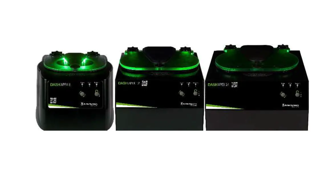
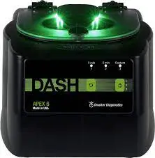
Drucker Diagnostics DASH Apex High G Force STAT Centrifuges
SYMBOLS
| Symbol | Definition | Use |
 | Caution | Caution to safety hazard. Potential risk of personal injury or damage to the instrument if improperly handled. Consult the manual before proceeding. |
 | Manufacturer | Manufacturer of record. |
 | Electrical and electronic products recycling symbol | Recycle only as electronic waste. Do not dispose in normal waste. |
 | RoHS Compliant | Compliance with RoHS environmental standards. |
 | CE Mark | Denotes conformity to specific European directives and regulations. |
 | MET Listing | Denotes conformity to specific safety standards and regulations. |
 | FDA Listed | Denotes that the product has been properly listed with the FDA. |
 | ISO Certification | Denotes conformity to quality standards and quality management systems. |
MODEL DESCRIPTION
DASH Apex is engineered for STAT sample processing. When used with the Drucker DASH Approach to centrifugation, the DASH Apex cuts your turnaround time (TAT) by up to 20 minutes.
This general-purpose laboratory centrifuge may also be used to spin approved containers with biologics, chemicals (non-flammable, non-explosive, non-volatile, and non-highly reactive), and environmental samples.
FEATURES
- Simple 2-Button interface
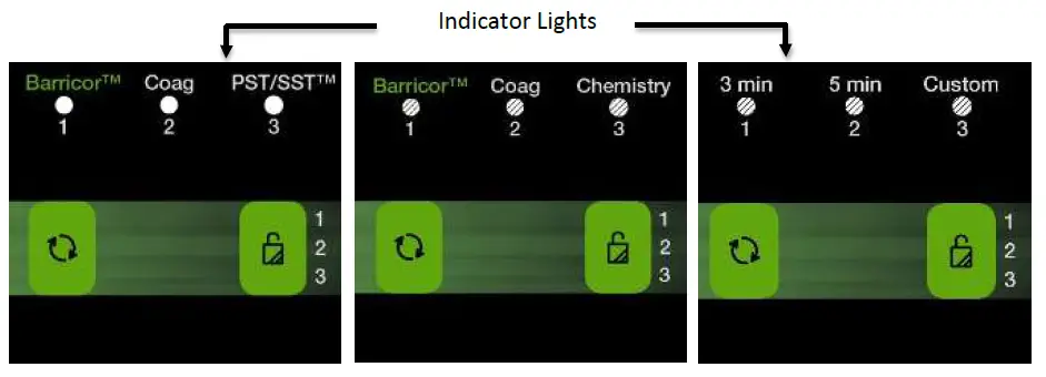
- Three (3) easily selectable pre-set cycles are conveniently labeled for your lab’s most common applications. Use the default cycles or settings can be customized. An LED light indicates the current selected setting.
- If desired, the control panel can be locked on one preset cycle, ideal for standardization to a single spin.
- Lid lighting indicates the centrifuge’s status (ready, running, done), keeping your TAT down (patent pending).
- A traditional audible alert indicates the completion of the cycle.
- Cool–Flow air flow design prevents overheating of samples by maintaining room temperature.
- Carbon fibers are used to reinforce the tube holders and provide high strength and durability.
- A clear lid permits safe observation of samples and optical calibration of speed.
- The lid safety system only allows entry into the centrifuge after the rotor has completely stopped.
- The lid safety system prevents the centrifuge from operating unless the lid is closed and latched.
- The high-power brushless DC motor provides years of operation with no routine maintenance.
INTENDED USE
General purpose laboratory centrifuge, intended for the density-based separation of fluids through centripetal acceleration.
WARRANTY
Drucker Diagnostics warranties that this centrifuge is free from defects in workmanship and parts for 2 years.
CAUTION AND WARNING STATEMENTS
- This device is intended to be operated by properly trained personnel who have carefully read the operating manual and are familiar with the function of the device. [Refer to the clinical laboratory method specified by the specimen receptacle manufacturer or established by the medical technology for the products applications.]
- For the safety of both the operator and service personnel, care should be taken when using this centrifuge if handling substances that are known to be toxic, radioactive or contaminated with pathogenic microorganisms. Use appropriate personal protection equipment (PPE). When Risk
- Group II materials are used, (as identified in the World Health Organization “Laboratory Bio-Safety Manual”), a Bio- Seal should be employed. In the event that materials of a higher risk group are being used, more than one level of protection must be provided. The use of flammable or explosive materials as well as those materials which have a vigorous chemical reaction is prohibited.
- Unplug the centrifuge before cleaning or performing maintenance.
- Inspect centrifuge for cracks or physical damage to cabinet, lid, rotor, or tube holders. Damage may result in unsafe operation. Discontinue use until repairs have been performed.
- This equipment generates, uses, and can radiate radio frequency energy, and if not installed and used in accordance with this operator manual, may cause interference to radio communications.
- Operation of this equipment in a residential area may cause interference, in which case the user will be required to correct the interference at his own expense.
- Due to the lack of the possibility of human exposure, all Drucker centrifuges and accessories sold by Drucker Diagnostics, Inc. are compliant without any special labeling required by the California Safe Drinking Water and Toxic Enforcement Act (Proposition 65).
INITIAL SETUP
- Unpack and verify that all the following are included:
- Centrifuge
- Power cord
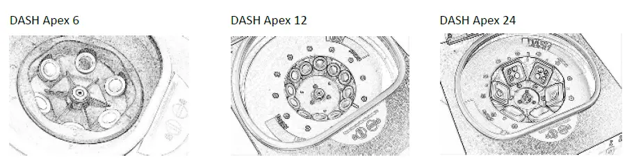
- Tube holders: 6 for Apex 6, 12 for Apex 12, or 6 buckets for Apex 24
- Quick Start Guide
- Setup the centrifuge on flat and level surface. A bench top clearance height of 21” (54 cm) is required to open the lid.
- The centrifuge should have 6” (15 cm) of clear space around the centrifuge. Proper ventilation is necessary to prevent the overheating of samples as well as premature failure of the centrifuge. Choose an area which allows unencumbered air flow, and where the temperature remains between 16°C and 32°C.
- No hazardous material shall be permitted in the clearance envelope during operation.
- The operator time within the envelope shall be limited to the time necessary for loading, unloading, and centrifuge operation only.
- Plug the line cord into the centrifuge.
- Plug the line cord into an electrical outlet.
- Turn on the power switch on the back of the centrifuge
BE SURE THE ELECTRICAL OUTLET IS ALWAYS ACCESSIBLE AS THE LINE CORD IS THE MEANS OF EMERGENCY DISCONNECTION!
OPERATION
- Place the tubes into the tube holders. Be sure to follow the rules for balanced loads as listed on page 8.
- Close the lid and turn the lid knob clockwise to its complete stop position.
- The LED light is on for the cycle currently selected. The selected cycle determines the run time and speed. To change the selected cycle, press the UNLOCK button in rapid succession until the desired cycle is selected. Two seconds after selection, the button reverts to its UNLOCK function.
- Pushing the START button on the control panel starts the spin cycle.
- When the cycle is completed, the rotor will slow to a complete stop and the lid light will flash.
- The locking mechanism will disengage for 60 seconds allowing entry into the rotor chamber. To unlock after more than 60 seconds have elapsed, press the UNLOCK button. The lid will unlock for another 15 seconds.
- Turn the lid knob counterclockwise and open the lid. The lid light will turn off.
- You may now safely remove the samples.
QUICK START
The LED indicator light is on for the cycle currently selected. Depending on your unit, you may have the following cycles:
- BarricorTM: For BD Vacutainer® BarricorTM tubes
- Coag: For Coagulation or Platelet Poor Plasma (PPP)
- PST/SSTTM: For BD PSTTM & SSTTM tubes with gel or blood tubes without gel
- Chemistry: For BD PSTTM II & SSTTM II tubes with gel or blood tubes without gel
- 3 Min: STAT centrifugation at 4,000 xg
- 5 Min: STAT centrifugation at 4,000 xg (6 and 12) or 3,000 xg (24)
- 6 Min: STAT centrifugation at 3,000 xg
- Custom: This setting can be customized to your lab’s validated cycles.
| Start | Begins running the cycle indicated by the cycle indicator LED light. The lid must be closed. | |
| Unlock | Allows access into the rotor chamber by disengaging the locking mechanism. Entry is only possible when the rotor is stopped. | |
| Stop | Pressing the UNLOCK button during operation will terminate the run and unlock the lid after the rotor has come to a stop. |
| Cycle Selection | The LED light is on for the cycle currently selected. To change the selected cycle, press the UNLOCK button in succession until the desired cycle is selected. Two seconds after selection, the button reverts to its UNLOCK function. | |
| Lock Cycle Selection | Select desired cycle. Press and hold the UNLOCK button for 5 seconds. Two beeps will confirm that cycle selection is locked. | |
| Unlock Cycle Selection | To re-enable cycle selection, press and hold the UNLOCK button for 5 seconds. Three beeps will confirm that cycle selection is now unlocked. |
SETTINGS

| Factory Settings | DASH Apex 6 | DASH Apex 12 | DASH Apex 24 | ||||||
| Cycle | RPM | Time | G-Force | RPM | Time | G-Force | RPM | Time | G-Force |
| 3 min | 5,300 | 3 | 4,000 | 5,200 | 3 | 4,000 | 4,200 | 5 | 3,000 |
| 5 min | 5,300 | 5 | 4,000 | 5,200 | 5 | 4,000 | 4,200 | 6 | 3,000 |
| Custom | 3,800 | 7 | 2,000 | 3,600 | 7 | 2,000 | 3,500 | 7 | 2,000 |

| Factory Settings | DASH Apex 6 | DASH Apex 12 | DASH Apex 24 | ||||||
| Cycle | RPM | Time | G-Force | RPM | Time | G-Force | RPM | Time | G-Force |
| BarricorTM | 5,300 | 3 | 4,000 | 5,200 | 3 | 4,000 | 4,200 | 5 | 3,000 |
| Coag | 5,300 | 5 | 4,000 | 5,200 | 5 | 4,000 | 4,200 | 6 | 3,000 |
| PST/SSTTM | 3,800 | 7 | 2,000 | 3,600 | 7 | 2,000 | 3,500 | 7 | 2,000 |

| Factory Settings | DASH Apex 6 | DASH Apex 12 | DASH Apex 24 | ||||||
| Cycle | RPM | Time | G-Force | RPM | Time | G-Force | RPM | Time | G-Force |
| BarricorTM | 5,300 | 3 | 4,000 | 5,200 | 3 | 4,000 | 4,200 | 5 | 3,000 |
| Coag | 5,300 | 5 | 4,000 | 5,200 | 5 | 4,000 | 4,200 | 6 | 3,000 |
| Chemistry (PSTII/SSTIITM) | 4,600 | 5 | 3,000 | 4,400 | 5 | 3,000 | 4,300 | 5 | 3,000 |
Custom cycles, if desired:
| Cycle Tube Type RPM G-Force (RCF) | |||
| 1 | |||
| 2 | |||
| 3 | |||
NOTE: Timer starts when speed reaches 90% of set speed. Deceleration time is not included in cycle time.
REVIEW CYCLE TIME AND SPEED SETTINGS
Your settings may not be standard. To review current settings, follow this procedure:
- The lid must be opened to review the selected cycle time and speed.
- Press and hold the START button until you hear a beep.
- Release the START button, the centrifuge will beep and the LED light will flash once for each minute of run time in the current cycle.
- Pressing the START button again will cause the unit to beep and the LED light to flash once for each 100 rpm in the current cycle.
- The centrifuge will automatically revert to normal mode at the end.
CHANGING CYCLE TIME AND SPEED SETTINGS
- The lid must be opened to change the selected cycle time and speed.
- Select the cycle you wish to change.
- Press and hold the START and UNLOCK buttons together until the LED light flashes.
- Press the START button for each minute of run time.
- Move to speed setting mode by pressing the UNLOCK button.
- Press the START button once for each 100 rpm.
- Press the UNLOCK button to exit setting mode.
BALANCING LOADS
Your centrifuge must contain a balanced load to work properly. Spinning balanced loads will extend the life of the centrifuge and produce better results. Use the following rules when loading the rotor. If an odd number of samples is to be spun, fill a tube with water to match the weight of the unpaired sample and place it across from this sample.
Opposing tube holders must be equally loaded or empty or loaded with equally weighted samples. When loading only 3 tubes, they must be of equal weight.
Buckets can be placed around the rotor in any of the rotor loading configurations shown. Each bucket must be loaded symmetrically with tubes as above.
CARE AND PREVENTATIVE MAINTENANCE
With proper care and maintenance, your centrifuge will provide years of laboratory service. For proper care, the following steps should be taken:
- Always Spin Balanced Loads: Make certain that you are always spinning a balanced load, as shown in the previous section. These centrifuges have a unique counter balanced motor mounting design which produces excellent vibration dampening. However, out–of–balance loads may break glass test tubes and may produce unsatisfactory separation results. Proper load balancing will improve sample separation and extend the life of the centrifuge.
- Motor and Electrical Maintenance: The highest quality electrical components have been selected for the DASH Apex centrifuges and should not need maintenance or servicing for the life of the centrifuge.
- Tube Holder Replacement: It is recommended that the tube holders be replaced after 24 months of use. Inspect tube holders regularly for cracks. If cracks are discovered, replace immediately.
- Remove Accessories Before Moving: All tube holders, samples, and caps must be removed from the rotor chamber before transporting or storing the centrifuge to prevent damage and injury.
CLEANING AND DISINFECTION
To prolong the life of the centrifuge, cleaning and disinfection is recommended every six months or whenever there is a spillage or tube breakage. Contaminants must be removed immediately or corrosion and premature degradation of components can occur. Before using any cleaning or decontamination methods other than those recommended by the manufacturer, users should verify with the manufacturer that the proposed method will not damage the equipment.
- Unplug the centrifuge before cleaning.
- Use appropriate personal protective equipment (PPE).
- Apply cleaning solutions with a towel or cloth. Do not submerge the centrifuge in water or other cleaning solutions as this will cause damage and void the warranty.
- ONLY isopropyl alcohol or a 10% (5500 PPM) bleach solution should be used to disinfect the centrifuge and its accessories.
- All surfaces must be dried immediately after cleaning and disinfecting.
TBQ GERMICIDAL PRODUCTS ARE NOT RECOMMENDED AS THEY MAY CAUSE DAMAGE TO THE CENTRIFUGE. REFRAIN FROM USING TO PREVENT VOIDING THE WARRANTY.
- Fully/partially halogenated hydrocarbons, ketones, esters, ethers, benzyls, ethyl benzenes, and all other chemicals not prescribed by the manufacturer shall not be used as they may cause damage to the rotor chamber, rotor, tube holders, accessories and centrifuge exterior and void the warranty.
TROUBLESHOOTING
NOTE: The latch must be turned completely clockwise to its stop position for the centrifuge to operate.
| The centrifuge does not run |
|
| The rotor does not spin freely |
|
| The centrifuge makes a rattling noise when running |
|
| Excessive noise or vibration when the centrifuge is running |
|
| The centrifuge stops and beeps continuously | The load is not balanced. Press the UNLOCK button, open the lid, and balance the load as recommended elsewhere in this manual. |
| The cycle time and speed are not set to the desired value | Check the setting by following the instructions in the section on Changing Cycle Settings. If the preset is not the desired length, follow the procedure on the same page to change the run preset time. |
| The centrifuge does not unlock after a run is completed |
|
| The lid does not open |
|
| Clicking noise during braking gets loud | Make sure that the screw in the center of the rotor is tight. |
| Lid does not stay up | Tighten the center screw on the lid hinge. |
GENERAL SPECIFICATIONS
The rotor and accessories are rated for the maximum rotation frequency shown in the table below.
| Apex 6 | Tube Capacity | 6 tubes – 3 to 10 mL |
| Radius with included accessories | 5 in (12.7 cm) | |
| Dimensions (Height x Width x Depth) | 8 in x 11 in x 13 in (20 cm x 28 cm x 34 cm) | |
| Weight | 12 lbs. (5.4 kg) | |
| Noise Level | 61 dB | |
| Environmental Range | 16 – 32 0C | |
| Voltage | 100 – 240 VAC | |
| Frequency | 50/60 Hz | |
| Power Requirement | 225 Watts | |
| Centrifuge Motor | ½ H.P. Brushless DC | |
| Maximum Speed | 5,300 RPM | |
| Cycle Time | 1 to 30 minutes (+/- 2%) |
| Apex 12 | Tube Capacity | 12 tubes – 3 to 10 mL |
| Radius with included accessories | 5.25 in (13.3 cm) | |
| Dimensions (Height x Width x Depth) | 9 in x 12.5 in x 14.75 in (23 cm x 32 cm x 37 cm) | |
| Weight | 34 lbs. (15 kg) | |
| Noise Level | 61 dB | |
| Environmental Range | 16 – 32 0C | |
| Voltage | 100 – 240 VAC | |
| Frequency | 50/60 Hz | |
| Power Requirement | 415 Watts | |
| Centrifuge Motor | ½ H.P. Brushless DC | |
| Maximum Speed | 5,200 RPM | |
| Cycle Time | 1 to 30 minutes (+/- 2%) |
| Apex 24 | Tube Capacity | 24 tubes – 3 to 10 mL |
| Radius with included accessories | 6 in (15.3 cm) | |
| Dimensions (Height x Width x Depth) | 9 in x 14.5 in x 17 in (23 cm x 37 cm x 43 cm) | |
| Weight | 39 lbs. (17 kg) | |
| Noise Level | 64 dB | |
| Environmental Range | 16 – 32 0C | |
| Voltage | 95 – 253 VAC | |
| Frequency | 50/60 Hz | |
| Power Requirement | 220 Watts | |
| Centrifuge Motor | ½ H.P. Brushless DC | |
| Maximum Speed | 4,300 RPM | |
| Cycle Time | 1 to 30 minutes (+/- 2%) |
Use only with approved accessories from the original manufacturer. A complete list of accessories is available at www.DruckerDiagnostics.com.
CALCULATING THE G-FORCE
The I.F.U.s of tube manufacturers recommend cycles at a minimum G-Force. For included accessories, a conversion table is shown below.
For other tube holders, the G-Force can be calculated if you know the RPM and the radius:
In Centimeters:
RCF or G-force = 0.00001118 x Rotor Radius (cm) x (RPM)2
| APEX 6 | APEX 12 | APEX 24 | |
| Radius | Radius | Radius | |
| 5.0 in | 5.25 in | 6.0 in | |
| 12.7 cm | 13.3 cm | 15.3 com | |
| RPM | G-Force | G-Force | G-Force |
| 1000 | 140 | 150 | 170 |
| 1100 | 170 | 180 | 210 |
| 1200 | 200 | 210 | 250 |
| 1300 | 240 | 250 | 290 |
| 1400 | 280 | 290 | 330 |
| 1500 | 320 | 340 | 380 |
| 1600 | 360 | 380 | 450 |
| 1700 | 400 | 450 | 500 |
| 1800 | 450 | 500 | 550 |
| 1900 | 500 | 550 | 600 |
| 2000 | 600 | 600 | 700 |
| 2100 | 650 | 650 | 750 |
| 2200 | 700 | 700 | 800 |
| 2300 | 750 | 800 | 900 |
| 2400 | 800 | 850 | 1000 |
| 2500 | 900 | 900 | 1050 |
| 2600 | 950 | 1000 | 1150 |
| 2700 | 1050 | 1100 | 1250 |
| 2800 | 1100 | 1200 | 1350 |
| 2900 | 1200 | 1250 | 1400 |
| 3000 | 1300 | 1350 | 1500 |
| 3100 | 1350 | 1400 | 1650 |
| 3200 | 1450 | 1500 | 1750 |
In Inches:
RCF or G-force = 0.0000284 x Rotor Radius (in) x (RPM)2
| APEX 6 | APEX 12 | APEX 24 | |
| Radius | Radius | Radius | |
| 5.0 in | 5.25 in | 6.0 in | |
| 12.7 cm | 13.3 cm | 15.3 com | |
| RPM | G-Force | G-Force | G-Force |
| 3300 | 1550 | 1600 | 1850 |
| 3400 | 1650 | 1700 | 2000 |
| 3500 | 1750 | 1800 | 2100 |
| 3600 | 1850 | 1950 | 2200 |
| 3700 | 1950 | 2050 | 2300 |
| 3800 | 2050 | 2150 | 2450 |
| 3900 | 2150 | 2300 | 2600 |
| 4000 | 2300 | 2400 | 2850 |
| 4100 | 2400 | 2500 | 2900 |
| 4200 | 2500 | 2600 | 3000 |
| 4300 | 2600 | 2750 | 3150 |
| 4400 | 2750 | 2900 | N/A |
| 4500 | 2900 | 3000 | N/A |
| 4600 | 3000 | 3150 | N/A |
| 4700 | 3150 | 3300 | N/A |
| 4800 | 3300 | 3450 | N/A |
| 4900 | 3400 | 3600 | N/A |
| 5000 | 3550 | 3750 | N/A |
| 5100 | 3700 | 3900 | N/A |
| 5200 | 3850 | 4000 | N/A |
| 5300 | 4000 | N/A | N/A |
REPLACEMENT PARTS DASH APEX 6
DASH APEX 6
Part No.: Description
- 7724037 Foot, rubber
- 02-002-1-0028 Lid Tray Assembly
- 02-001-0-0011 Rotor Assembly, Dash Apex 6
- 02-005-1-0010 Motor Assembly
- 02-006-0-0011 PC Board
- 7760006 Power cord
- 03-1-0005-0192 Internal Power Supply
- 02-002-1-0027 Lid Assembly
- 7724071 Hinge, friction
- 02-002-1-0056 Seal, lid gasket
- 03-0-0003-0313 Open/Close Label
- 03-1-0007-0046 75/100mm Tube Holder, Black
- 02-002-1-0026 Lid LED Assembly, Green
- 03-1-0001-0090 Button Cover No Emboss
- 03-1-0001-0089 Button Cover Embossed
- 03-1-0002-0099 Button Protector
DASH APEX 12
Part No. : Description
- 7724177 Foot, rubber
- 02-006-1-0044 Locking Lid Tray Assembly, 11”
- 02-001-0-0009 12-Place Rotor, Horizontal
- 02-005-1-0012 Motor Assembly
- 02-006-0-0011 PC Board
- 7760006 Power cord
- 03-1-0005-0193 Power Supply
- 02-002-1-0041 Lid Assembly
- 02-002-1-0057 Seal, lid gasket
- 03-0-0003-0313 Open/Close Label
- 03-1-0007-0046 75/100mm Tube Holder, Black
- 03-1-0001-0090 Button Cover No Emboss
- 03-1-0001-0089 Button Cover Embossed
- 03-1-0002-0099 Button Protector
- 00-100-100-005 Replacement Grommet & Bushing Kit
DASH APEX 24
Part No. Description
- 7728052 Foot, rubber
- 02-006-1-0044 Locking Lid Tray Assembly, 11”
- 02-001-0-0008 24-Place Rotor, Horizontal
- 02-005-1-0012 Motor Assembly
- 02-006-0-0011 PC Board
- 7760006 Power cord
- 03-1-0005-0193 Power Supply
- 02-002-1-0037 Lid Assembly
- 7724071 Hinge, friction
- 02-002-1-0058 Seal, lid gasket
- 03-0-0003-0313 Open/Close Label
- 02-004-0-0012 4 Place Carrier, Carbon Fiber
- 03-1-0001-0090 Button Cover No Emboss
- 03-1-0001-0089 Button Cover Embossed
- 03-1-0002-0099 Button Protector
- 00-100-100-005 Replacement Grommet & Bushing Kit
Product Family: DASH Apex Series (Apex 6, Apex 12, Apex 24)
Complies with UL61010-1/CSA C22.2 No. 61010-1 and IEC61010-2-020
Protected by U.S. Patents #6,811,531, #D718,463, & #D734,489. Other Patents Pending 
INSTRUCTIONS FOR DISPOSAL OF WEEE BY USERS IN THE EUROPEAN UNION
This product must not be disposed of with other waste. Instead, it is the user’s responsibility to dispose of their waste equipment by handing it over to a designated collection point for the recycling of waste electrical and electronic equipment. The separate collection and recycling of your waste equipment at the time of disposal will help to conserve natural resources and ensure that it is recycled in a manner that protects human health and the environment. For more information about where you can drop off your waste equipment for recycling, please contact your local city office, waste disposal service, or where you purchased the product.
200 SHADY LANE, SUITE 170 – PHILIPSBURG, PA 16866,
USA +1-866-265-1486 (U.S. ONLY) – +1-814-692-7661
[email protected]
DRUCKERDIAGNOSTICS.COM
This operator’s manual is part number 03-0-0002-0120 Rev. G


