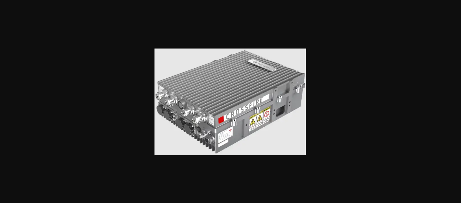

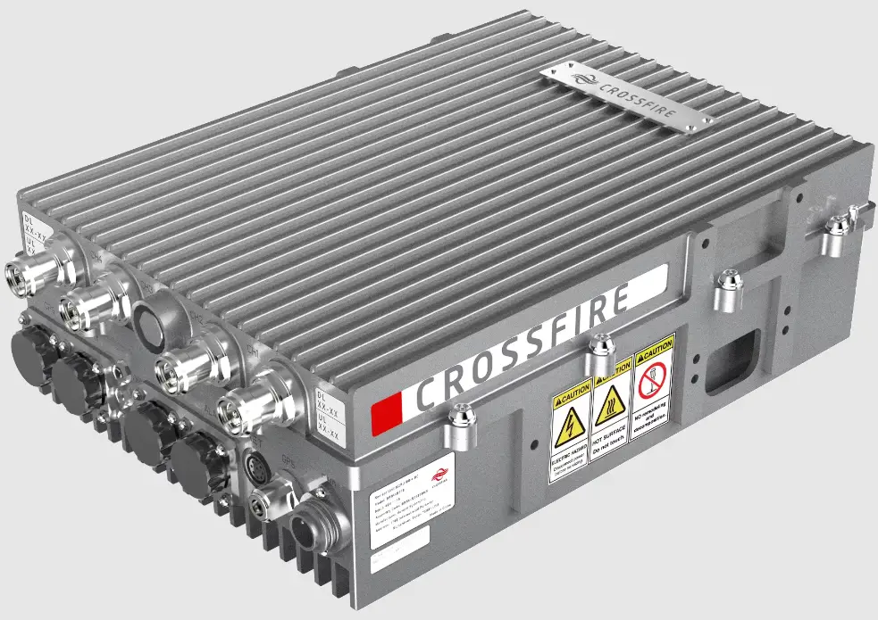
sunWAVE M2RU CrossFire 4T4R Digital Radios
Revision History
| Revision Number | Revision Date | Summary of Changes | Author |
| 1.0.0 | 29th April 2020 | Initial Version | Allen Chu |
| 1.0.1 | 4th Aug 2020 | Add ordering information | Allen Chu |
| 1.0.2 | 10th Aug 2021 | Add ordering information | Allen Chu |
Copyright © 2022 Sunwave All rights reserved.
No part of this publication may be reproduced, transmitted, transcribed, stored in a retrieval system, or translated into any language, in any form or by any means, electronic, mechanical, photocopying, recording, or otherwise, without prior written permission from Sunwave.
All copyright, confidential information, patents, design rights and all other intellectual property rights of whatsoever nature contained herein are and shall remain the sole and exclusive property of Sunwave. The information furnished herein is believed to be accurate and reliable.
However, no responsibility is assumed by Sunwave for its use, or for any infringements of patents or other rights of third parties resulting from its use.
The Sunwave and CrossFire names and logos are trademarks or registered trademarks of Sunwave.
All other trademarks are the property of their respective owners.
This is NOT a CONSUMER device. It is designed for installation by FCC LICENSEES and QUALIFIED INSTALLERS. You MUST have an FCC LICENSE or express consent of an FCC License to operate this device.
NOTE: Only authorized person can enter the area where the antenna is installed. And the person is fully aware of the potential for exposure and can exercise control over his or her exposure by leaving the area or by some other appropriate means. Awareness of the potential for RF exposure in a workplace or similar environment can be provided through specific training as part of a RF safety program. For pluggable equipment, the socket-outlet shall be easily accessible.
Overview
CrossFire M2RU is a digital transport platform supporting cellular and wideband public safety technologies on fibre optic cable using the CPRI protocol. The power amplifier technology adopts Digital Pre-Distortion, allowing for a significant improvement in power consumption compared with analogue technology. This platform is ideal for multi-operator multi-band deployments of cellular services into underground tunnels & outdoor coverage areas.
Key Features
- Single Band 4T4R: Up to 37dBm Output Power
- Dual Bands 2T2R: Supports External Alarm
- Supports TDD & FDD: Up to 100MHz IBW
- Supports Sub-6GHz: 5GNR Compliant
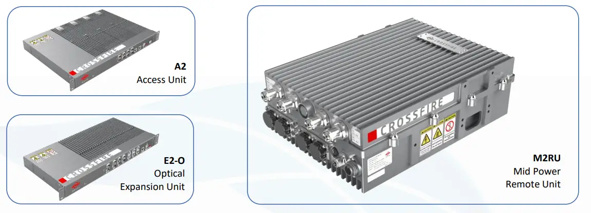
System Elements 
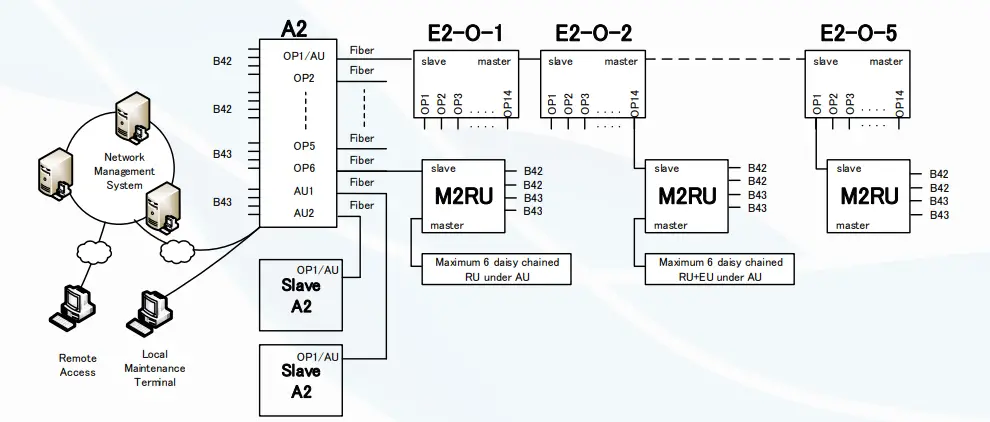
Block Diagram 
Technical Specifications
| System | |
| Maximum RF Bands per Access Unit | 4 |
| Maximum RF Channels per Remote Unit | 4 |
| Maximum Access Units per System | 3 (1 x Master A2 / 2 x Slaves A2) |
| Maximum E2s per Master A2 | 8 |
| Maximum E2s cascaded | 5 |
| Maximum RUs cascaded | 6 |
| Frequency Range (Non-Contiguous) | 600MHz – 6000MHz |
| Bandwidth per Channel (Downlink & Uplink) | ≤100MHz (Contiguous) |
| Digital Bandwidth per Channel (Downlink & Uplink) | 20 / 30 / 40 / 50 / 60 / 80 / 100MHz |
| Bandwidth per System (Downlink & Uplink) | ≤400MHz (in each direction) |
| System Delay Adjustment | Up to 80.00µs @ 1us step, manual & auto, Band based. |
| Redundancy | Fiber Loopback |
| VSWR | 1.5 |
Forward Path (Downlink)
| Number of Carriers | 1 | 2 | 4 | 8 | 16 |
| Output Power per Carrier(dBm) | 37 | 34 | 31 | 28 | 25 |
| Maximum Gain | 37 ± 2dB | ||||
| Maximum Input Power | +15dBm (with AGC operating) / 0dBm (without AGC operating) | ||||
| EVM | <3.5% @ 256 QAM | ||||
| Ripple | 4dB Typical | ||||
| Manual Attenuation Control | 40dB @ 1dB/step (A2: 25dB, RU: 15dB) | ||||
| System Delay (A2+E2+RU) | 12µS | ||||
Reverse Path (Uplink)
| Reverse Path (Uplink) | |
| Maximum Output Power per Band | -13dBm |
| Maximum Gain | 37 ± 2dB |
| Maximum Input Power | -35dBm |
| Ripple | 4dB Typical |
| Manual Gain Control | 40dB @ 1dB/step (AU: 25dB, RU: 15dB) |
| System Delay (A2+E2+RU) | 8µS |
| Noise Figure | 4dB Typical @ Maximum Gain |
Interfaces
| Interfaces | |
| Antenna Interface (All bands) | 4.3-10 Female |
| Access Unit RF Interface | QMA Female |
| Optical Connector Type | SFP+, Standard LC |
| Optical Transmission Rate | 10.1376Gb/s |
| Optical Fibre Length | 1.4km / 10km / 30km 0.87mi / 6.21mi / 18.64mi |
| Dry Contact | AU: 4 Inputs & 4 Outputs, NO and NC Mode RU: 2 Inputs & 2 Outputs, NO and NC Mode |
| Maintenance Interface | Ethernet RJ45 |
Supported Bands
| Supported Bands | ||||
| Band | 3GPP Band | Downlink | Uplink | Max Bandwidth |
| 3500MHz | 42 | 3400-3600 | 3400-3600 | 100 |
| 3500MHz | 42* | 3450-3650 | 3450-3650 | 100 |
| 3600MHz | 48 | 3550-3700 | 3550-3700 | 100 |
| 3700MHz | 43 | 3600-3800 | 3600-3800 | 100 |
| 2500MHz TDD | 41 | 2496-2690 | 2496-2690 | 100 |
| 2300MHz TDD | 40 | 2300-2400 | 2300-2400 | 100 |
| 1800MHz | 3 | 1805-1880 | 1710-1785 | 75 |
| 1900MHz | 25 | 1930-1995 | 1850-1915 | 65 |
| 2100MHz | 1 | 2110-2170 | 1920-1980 | 60 |
| 2100MHz AWS | 66E | 2110-2200 | 1710-1780 | 90 |
| 2600MHz | 7 | 2620-2690 | 2500-2570 | 70 |
Electrical
| Electrical | |
| Complies with | 3GPP TS36.106 | 3GPP TS25.106 |
| EMC | EN 301489-1 / -50, EN 50121-4, EN 55032, EN 61000-4 series |
| Safety | EN 60950-1, EN 60950-22, EN 62368-1, EN 50385 |
| Maximum Power Consumption (A2/E2/RU) | 80W / 50W / 150W |
| Power Supply | 100-240V AC, 50/60Hz | 48VDC ± 20% |
Environmental
| Environmental | |
| Mean Time Between Failure (MTBF) | >100,000 hours |
| Operating Temperature (A2/E2) | -10°C to +50°C / 14°F to +122°F |
| Operating Temperature (RU) | -40°C to +55°C / -40°F to +131°F |
| Humidity | 5% to 100% (Non-Condensing) |
| Cooling | Passive |
| Installation | A2/E2: Wall or 19” Rack | RU: Wall or Pole |
| Ingress Protection Rating | A2/E2: IP30 (Indoor) | RU: IP67 (Outdoor) |
Mechanical
| Mechanical | |
| A2 (Width / Height / Depth / Weight) | 440mm / 44mm / 329mm / 8.0kg (17.32in / 1.73in / 12.95in / 17.64lb) |
| E2-O (Width / Height / Depth / Weight) | 440mm / 44mm / 220mm / 5.0kg (17.32in / 1.73in / 8.66in / 11.02lb) |
| RU (Width / Height / Depth / Weight) | 360mm / 115mm / 260mm / 11.0kg (14.17in / 4.53in / 10.24in / 24.25lb) |
Element Management
| Element Management | |
| OMT (Operations and Maintenance Terminal) | RJ45. Access via A2, E2 or RU (Web Based) |
| LMS (Local Management System) | Yes (Ordered separately) |
| Remote Alarming | SNMP V2C & V3, Dry Contact (NO or NC mode) |
Ordering Information
| Part Code | Part Description |
| Access Unit Chassis (2nd Generation) | |
| A2-4-AC | Access Unit Chassis, 4 Bands, 360 – 3800MHz supported, 100-240v AC Powered |
| A2-4-DC | Access Unit Chassis, 4 Bands, 360 – 3800MHz supported, ±48v DC Powered |
| Access Unit Modules | |
| AU-AC-M1800 | Access Unit Module, 4 Way Active Combiner 1800MHz (UL 1710-1785 / DL 1805-1880) |
| AU-AC-M1900 | Access Unit Module, 4 Way Active Combiner 1900MHz (UL 1850-1915 / DL 1930-1995) |
| AU-AC-M2100E | Access Unit Module, 4 Way Active Combiner 2100MHz AWS (UL 1710-1780 / DL 2110-2200) |
| AU-AC-M2100 | Access Unit Module, 4 Way Active Combiner 2100MHz (UL 1920-1980 / DL 2110-2170) |
| AU-AC-M2300T | Access Unit Module, 4 Way Active Combiner 2300MHz TDD (2300-2400) |
| AU-AC-M2500T | Access Unit Module, 4 Way Active Combiner 2500MHz TDD (2496-2690) |
| AU-AC-M2600 | Access Unit Module, 4 Way Active Combiner 2600MHz (UL 2500-2570 / DL 2620-2690) |
| AU-AC-M3500T | Access Unit Module, 2 Way Active Combiner 3500MHz TDD (3400-3600) |
| AU-AC-M3550T | Access Unit Module, 2 Way Active Combiner 3500MHz TDD (3450-3650) |
| AU-AC-M3600T | Access Unit Module, 2 Way Active Combiner 3600MHz TDD (3550-3700) |
| AU-AC-M3700T | Access Unit Module, 2 Way Active Combiner 3700MHz TDD (3600-3800) |
| AU/RU-NC | Blanking Card to suit AU or Indoor Low Power RU |
| Expansion Units | |
| E2-O-14-AC | Expansion Unit Supports up to 14 x Optical Outputs, AC Powered |
| E2-O-14-DC | Expansion Unit Supports up to 14 x Optical Outputs, DC Powered |
| Remote Unit Chassis | |
| M2RU-OD-4-DC | Outdoor Mid Power Remote Unit, Sub6GHz, Dual Band 2T2R or Single Bands 4T4R, DC Powered |
| Remote Unit Modules | |
| M2RU-OD-M1800 | Outdoor Mid Power Remote Unit PA Module, 1800MHz (UL 1710-1785 / DL 1805-1880), 2T2R |
| M2RU-OD-M1900 | Outdoor Mid Power Remote Unit PA Module, 1900MHz (UL 1850-1915 / DL 1930-1995), 2T2R |
| M2RU-OD-M2100E | Outdoor Mid Power Remote Unit PA Module, 2100MHz AWS (UL 1710-1780 / DL 2110-2200), 2T2R |
| M2RU-OD-M2100 | Outdoor Mid Power Remote Unit PA Module, 2100MHz (UL 1920-1980/ DL 2100-2170), 2T2R |
| M2RU-OD-M2300T | Outdoor Mid Power Remote Unit PA Module, 2300MHz TDD (2300-2400), 2T2R |
| M2RU-OD-M2500T | Outdoor Mid Power Remote Unit PA Module, 2500MHz TDD (2496-2690), 2T2R |
| M2RU-OD-M2600 | Outdoor Mid Power Remote Unit PA Module, 2600MHz (UL 2500-2570 / DL 2620-2690), 2T2R |
| M2RU-OD-M3500T | Outdoor Mid Power Remote Unit PA Module, 3500MHz TDD (3400-3600), 2T2R |
| M2RU-OD-M3550T | Outdoor Mid Power Remote Unit PA Module, 35500MHz TDD (3450-3650), 2T2R |
| M2RU-OD-M3600T | Outdoor Mid Power Remote Unit PA Module, 3600MHz TDD CBRS (3550-3700), 2T2R |
| M2RU-OD-M3700T | Outdoor Mid Power Remote Unit PA Module, 3700MHz TDD (3600-3800), 2T2R |
| Other Items | |
| FAN-1U-AC | AC Fan Unit to support AU & LPRU Chassis, 1U Rack Unit Height, 100-240v AC Powered |
| FAN-1U-DC | DC Fan Unit to support AU & LPRU Chassis, 1U Rack Unit Height, ±48v DC Powered |
| M2RU-PSU48S | AC Power Supply Unit to support M2RU, 110-240v AC, Support Lightning Protection, 20kA |
| M2RU-EXL | IP65 Cable Accessories for External Alarm Port |
FCC Warning:
This device complies with Part 15 of the FCC Rules. Operation is subject to the following two conditions:
- This device may not cause harmful interference, and
- This device must accept any interference received, including interference that may cause undesired operation.
Part20 Warning :
Note: This product has been tested and found to comply with the limits for a Class B digital device, pursuant to Part 15 of the FCC Rules. These limits are designed to provide reasonable protection against harmful interference in a residential installation. This product generates, uses, and can radiate radio frequency energy and, if not installed and used in accordance with the instructions, may cause harmful interference to radio communications. However, there is no guarantee that interference will not occur in a particular installation. If this product does cause harmful interference to radio or television reception, which can be determined by turning the equipment off and on, the user is encouraged to try to correct the interference by one or more of the following measures:
- Reorient or relocate the receiving antenna.
- Increase the separation between the equipment and receiver.
- Connect the equipment into an outlet on a circuit different from that to which the receiver is connected.
- Consult the dealer or an experienced radio/TV technician for help.
Contact us today:
www.sunwave.com
[email protected]


