![]() KTM 990 Supermoto Fuel Control Module
KTM 990 Supermoto Fuel Control Module
Installation Guide
KTM 990 Supermoto Fuel Control Module
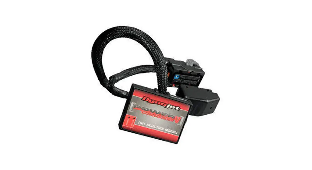
POWER COMMANDER 6
Installation Guide for PC6-18005
Model Coverage: 2009-2013 KTM 990 SMR/SMT
PARTS LIST
- 1 POWER COMMANDER 6
- 1 INSTALLATION GUIDE
- 1 USB CABLE
- 2 DYNOJET DECALS
- 2 POWER COMMANDER DECALS
- 2 VELCRO STRIPS
- 1 ALCOHOL SWAB
PLEASE READ ALL DIRECTIONS BEFORE STARTING INSTALLATION.
THE IGNITION MUST BE TURNED OFF BEFORE INSTALLATION.
INPUT ACCESSORY GUIDE
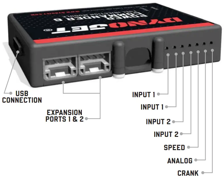
OPTIONAL ACCESSORY INPUTS
| Map | (Input 1 or 2) The PC6 has the ability to hold 2 different base maps. You can switch on the fly between these two base maps when you hook up a switch to the MAP inputs. You can use any open/close type switch. The polarity of the wires is not important. |
| Shifter | (Input 1 or 2) Used for clutch-less full-throttle upshifts. Insert the wires from the Dynojet quick shifter into either Input 1 or Input 2. The polarity of the wires is not important. Set to Input 2 by default. |
| Speed | If your application has a speed sensor then you can tap into the signal side of the sensor and run a wire into this input. This will allow you to calculate gear position in the Control Center Software. Once gear position is set up you can alter your map based on gear position and setup gear-dependent kill times when using a quick shifter. |
| Analog | This input is for a 0-5v signal such as engine temp, boost, etc. Once this input is established you can alter your fuel curve based on this input in the Power Core software. |
| Launch | You can connect a wire to either Input 1 or Input 2 and then the other end to a switch. This switch when engaged (continuity) will only allow the RPM to be raised to a certain limit (set in the software). When released, you will have full RPM. |
WIRE CONNECTIONS
To input wires into the PC6 first remove the rubber plug on the backside of the unit and loosen the screw for the corresponding input. Using a 22-24 gauge wire, strip about 10mm from its end. Push the wire into the hole of the PC6 until it stops and then tighten the screw. Make sure to reinstall the rubber plug.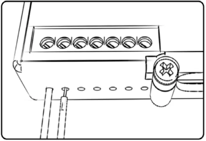
NOTE: If you tin the wires with solder it will make inserting them easier.
INSTALLING THE POWER COMMANDER 6
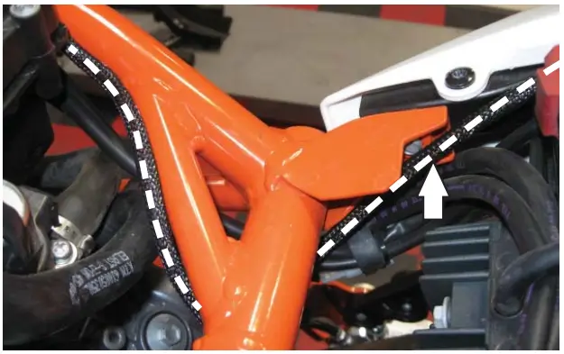 | 1. Remove the seat, both side fairings, and the chin fairing. 2. Prop the fuel tank up. 3. Using the supplied Velcro, secure the PC6 module in the tail section. Clean both surfaces with the supplied alcohol swab prior to applying the Velcro adhesive. 4. Route the PC6 harness along the frame going under the crossover section. |
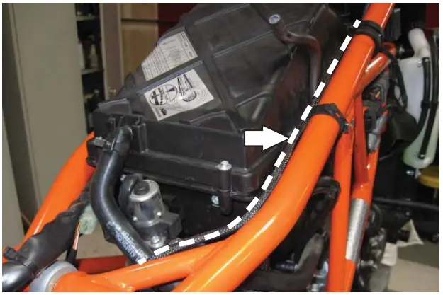 | 5. Continue routing the harness along the right side of the frame between the frame and the air box. Use the stock wire ties to secure the PC6 harness in place. |
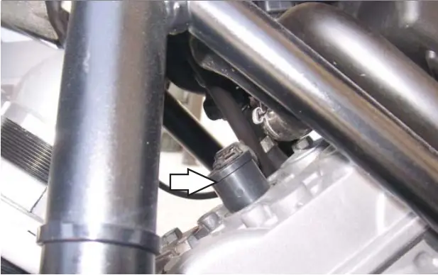 | 6. Locate the Rear Ignition Coil and unplug the stock wiring harness from the coil. Rotate the coil stick 180 degrees so the connection is pointing to the right side of the motorcycle. |
 | 7. Plug the pair of PC6 connectors with BLUE-colored wires in-line with the Rear Ignition Coil and the stock wiring harness. |
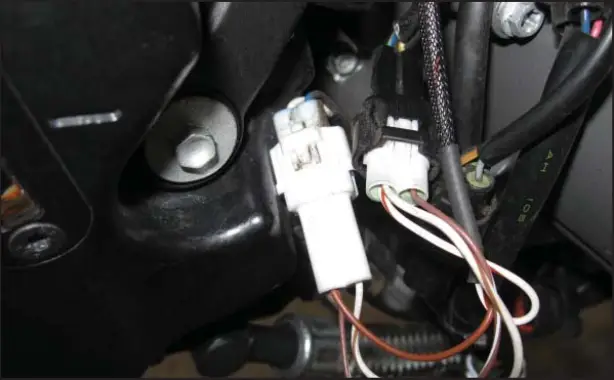
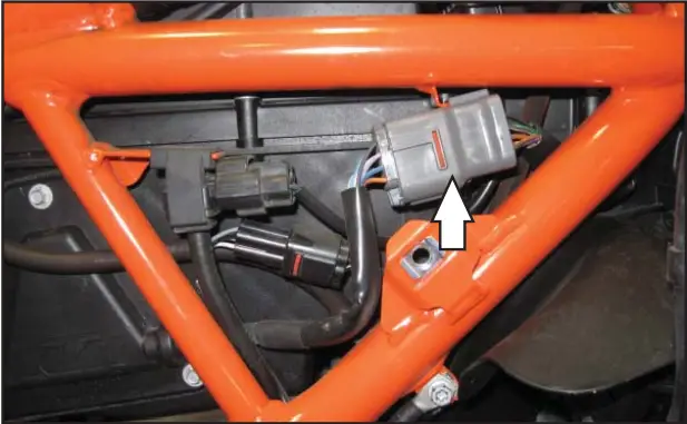 | 8. Locate the stock connector from the throttle bodies on the right side of the motorcycle. Unplug this connector. |
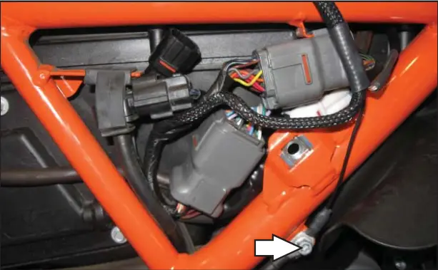 | 9. Plug the PC6 in line with the stock wiring harness. |
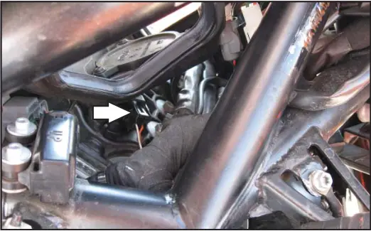 | 11. Locate the Front Ignition Coil and unplug the stock wiring harness from the coil. |
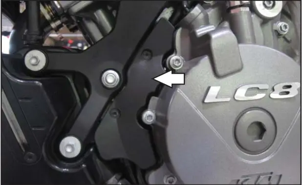 | 13. Remove the small plastic cover on the left side of the engine. |
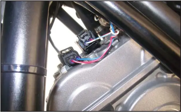
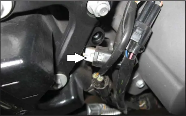 | 14. Unplug the stock Crank Position Sensor connectors. This is a 2-pin connector pair. The MALE connector is WHITE. The FEMALE connector is BLACK. |
 | 15. Plug the PC6 wiring harness in line with the stock CPS connectors. 16. Reinstall the small plastic cover. 17. Reinstall the fuel tank, all of the removed bodywork, and the seats. Download the latest map files from our website at dynojet.com/tunes. |
![]() PUSH THE LIMIT
PUSH THE LIMIT
2191 MENDENHALL DRIVE, NORTH LAS VEGAS,
NV 89081 – 800-992-4993
DYNOJET.COM
© 2009-2022 DYNOJET RESEARCH ALL RIGHTS RESERVED
2009-2013 KTM 990 SMR/SMT
PC6-18005


 Fuel Injection Module Installation Guide")


