![]()
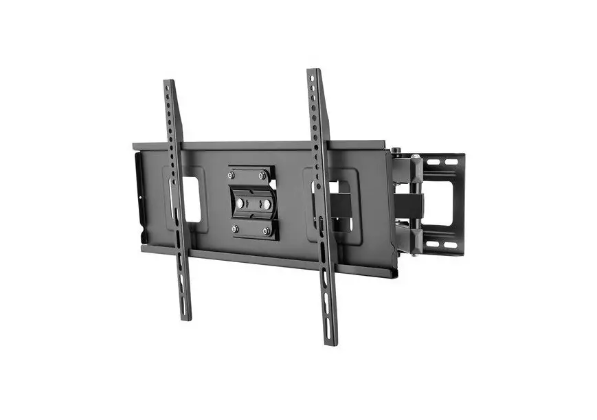
Full Motion Mount for TVs 47″ – 70″
DX-HTVMM1703-C
- 7.9 × 7.9″ (200 × 200 mm)
- 11.8 × 7.9″ (300 × 200 mm)
- 11.8 × 11.8″ (300 × 300 mm)
- 15.7 × 7.9″ (400 × 200 mm)
- 15.7 × 11.8″ (400 × 300 mm)
- 15.7 × 15.7″ (400 × 400 mm)
- 19.7 × 15.7″ (500 × 400 mm)
- 23.6 × 15.7″ (600 × 400 mm)
![Dynex Dynex 47-75 Full Motion TV Wall Mount User Manual [DX-HTVMM1703-C]](https://manualsee.com/img/385/52714/2021/01/Dynex-Dynex-47-75-Full-Motion-TV-Wall-Mount-User-Manual-DX-HTVMM1703-C-300x219.png)
USER GUIDE
Before using your new product, please read these instructions to prevent any damage.
Safety information and specifications

3 DX-HTVMM1703-C Full Motion Mount for TVs 47″ – 70″
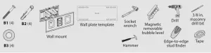
Tools needed
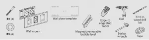
 Edge-to-edge stud finder
 Pencil
![]() Phillips screwdriver
Phillips screwdriver
 Measuring tape
 Drill
Drill
 Hammer
 Socket wrench
 Tape
Tape
 5 × Allen wrench
 3/16 in. (5 mm) wood drill bit (for wood stud wall) or 3/8 in. (10 mm) masonry drill bit (for concrete wall)
Package contents
Make sure that you have all the hardware necessary to assemble your new TV wall mount:

Wall Mount (1)
![]()
TV Brackets (2)

Wall Plate Template (1)
4 DX-HTVMM1703-C Full Motion Mount for TVs 47″ – 70″
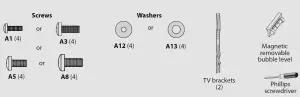
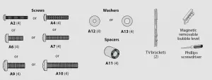
TV Hardware Bag
Label Hardware Qty.
A1 ![]() M4 × 12 mm screw 4
M4 × 12 mm screw 4
A2 ![]() M4 × 30 mm screw 4
M4 × 30 mm screw 4
A3 ![]() M5 × 12 mm screw 4
M5 × 12 mm screw 4
A4 ![]() M5 × 30 mm screw 4
M5 × 30 mm screw 4
A5 ![]() M6 × 12 mm screw 4
M6 × 12 mm screw 4
A6 ![]() M6 × 20 mm screw 4
M6 × 20 mm screw 4
A7 ![]() M6 × 35 mm screw 4
M6 × 35 mm screw 4
A8  M8 × 16 mm screw 4
A9  M8 × 25 mm screw 4
A10  M8 × 50 mm screw 4
A11  Spacer 4
A12 ![]() M4/M5 washer 4
M4/M5 washer 4
A13 ![]() M6/M8 washer 4
M6/M8 washer 4
B1  Lag bolt 4
B2  Concrete anchor 4
B3 ![]() Lag bolt washer 4
Lag bolt washer 4
 Magnetic removable bubble level 1
![]() Popper button 3
Popper button 3

5 DX-HTVMM1703-C Full Motion Mount for TVs 47″ – 70″
Installation instructions
STEP 1 – Determine whether your TV has a flat back or an irregular or obstructed back
- Carefully place your TV screen face-down on a cushioned, clean surface to protect the screen from damages and scratches.
- If your TV has a table-top stand attached, remove the stand. See the documentation that came with your TV for instructions.
- Lay the TV brackets, oriented vertically, on the back of your TV.
- Align the screw holes in the TV brackets with the mounting screw holes on your TV.
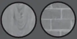
- Identify which type of back your TV has:
Flat back: The brackets lay flush against the back of your TV and do not block any jacks. You do not need spacers when assembling the wall mount.

Obstructed back: The brackets block one or more of the jacks on the back of your TV. You will need spacers when assembling the wall mount.

Irregularly-shaped back: There is a gap between a bracket and some part of the back of your TV. You will need spacers when assembling the wall mount.

6. Remove the TV brackets.
6 DX-HTVMM1703-C Full Motion Mount for TVs 47″ – 70″
STEP 2 – Select screws, washers, and spacers
1 Select the hardware for your TV (screws, washers, and spacers). A limited number of TVs come with mounting hardware included. (If there are screws that came with the TV, they are almost always in the holes on the back of the TV.) If you don’t know the correct length of the mounting screws your TV requires, test various sizes by hand-threading the screws.
Select one of the following types of screws:
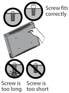
 CAUTION: To avoid potential personal injuries and property damage, make sure that there are adequate threads to secure the brackets to your TV. If you encounter resistance, stop immediately and contact customer service. Use the shortest screw and spacer combination to accommodate your TV. Using hardware that is too long may damage your TV. However, using a screw that is too short may cause your TV to fall from the mount.
- Align the left and right TV brackets with the screw holes on the back of the TV. Make sure that the brackets are level.
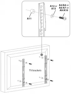
- Install washers (A12 or A13) and screws (A1, A3, A5, or A8) into the holes in the back of the TV.
- Tighten the screws until they are snug against the TV brackets. Do not over tighten.

- Place spacers(A11) over the holes on the back of the TV.
- Align the left and right TV brackets with the screw holes on the back of the TV. Make sure that the brackets are level.
- Place washers (A12 or A13) over the holes in the TV brackets. Insert screws (A2, A4, A6, A7, A9, or A10) through the washers, TV brackets, and spacers and into the screw holes on the back of the TV.
- Tighten the screws until they are snug against the TV brackets. Do not over tighten.
- Measure the distance from the bottom of your TV to the center point halfway between the top and bottom mounting holes on the back of your TV. This is measurement a.
- Measure the distance from the floor to where you want the bottom of the TV to be placed on the wall. Keep in mind that the bottom of the TV should be placed above any furniture (such as entertainment centers or TV stands). The TV should also be above items placed on top of the furniture (like a Blu-ray player or cable box). This measurement is b.
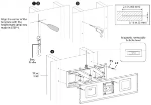
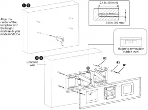
- Add a + b. The total measurement is the height where you want the center of the wall plate to be on the wall.
- Use a pencil to mark this spot on the wall.


- Locate the stud. Verify the center of the stud with an edge-to-edge stud finder.
- Align the center of the wall plate template at the height (a + b) you determined in the previous step, make sure that the template is level, then tape it to the wall.
- Drill four pilot holes through the template to a depth of 2.4 in. (60 mm) using a 3/16 in. (5 mm) diameter drill bit, then remove the template.
- Align the wall plate on the wall mount with the pilot holes, insert the lag bolts (B1) through the lag bolt washers (B3), then through the holes in the wall plate. Make sure that the wall plate is level. Tighten the lag bolts with a socket wrench only until they are firm against the wall plate.
- Align the center of the wall plate template at the height (a + b) you determined in the previous step, make sure that it is level, then tape it to the wall.
- Drill four pilot holes through the template to a depth of 2.4 in. (60 mm) using a 3/8 in. (10 mm) diameter masonry drill bit, then remove the template.
- Insert the concrete wall anchors (B2) into the pilot holes and use a hammer to make sure that the anchors are flush with the concrete surface.
- Align the wall plate on the wall mount with the anchors, insert the lag bolts (B1) through the lag bolt washers (B3), then through the holes in the wall plate. Make sure that the wall plate is level. Tighten the lag bolts with a socket wrench only until they are firm against the wall plate.
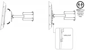
- Holding the TV with the top of the screen tilted toward the wall, slide the upper edges of the right and left TV brackets into the notches on the upper lip of the TV wall plate.
- Push the bottom of the TV toward the wall until the safety bolts click into place, then tighten the bolts with a Phillips screw driver.
- Thread cables for attached devices along the mounting arm, then snap the popper buttons over the cables to hold them in place.

- To adjust the arms’ tension (to make the arm easier or harder to move), loosen or tighten the tension screws with an Allen wrench.
- To rotate the TV left or right, hold the sides of the TV, then push one side while pulling the other side.
- To tilt of the TV up or down, hold the top and bottom of the TV, then tilt the TV forward or backward.

One-year limited warranty – Dynex
Definitions:
- Customer instruction/education
- Installation
- Set up adjustments
- Cosmetic damage
- Damage due to acts of God, such as power surges
- Accident(s)
- Misuse
- Abuse
- Negligence
- Commercial purposes/use, including but not limited to use in a place of business or in communal areas of a multiple dwelling condominium or apartment complex, or otherwise used in a place of other than a private home.
- Modification of any part of the Product, including the antenna
- Display panel damaged by static (non-moving) images applied for lengthy periods (burn-in).
- Damage due to incorrect operation or maintenance
- Connection to an incorrect voltage or power supply
- Attempted repair by any person not authorized by Dynex to service the Product
- Products sold “as is” or “with all faults”
- Consumables, including but not limited to batteries (i.e. AA, AAA, C etc.)
- Products where the factory applied serial number has been altered or removed
- Loss or Theft of this product or any part of the product
- Display panels containing up to three (3) pixel failures (dots that are dark or incorrectly illuminated) grouped in an area smaller than one tenth (1/10) of the display size or up to five (5) pixel failures throughout the display. (Pixel based displays may contain a limited number of pixels that may not function normally.)
- Failures or Damage caused by any contact including but not limited to liquids, gels or pastes.
Dynex 47″-75″ Full Motion TV Wall Mount User Manual [DX-HTVMM1703-C] – Original PDF


 Experience the power of QLED User Manual")
