Ford F-150 Fuse Box Diagram + Location
 Ford F-150 Fuse Box Diagram + Location
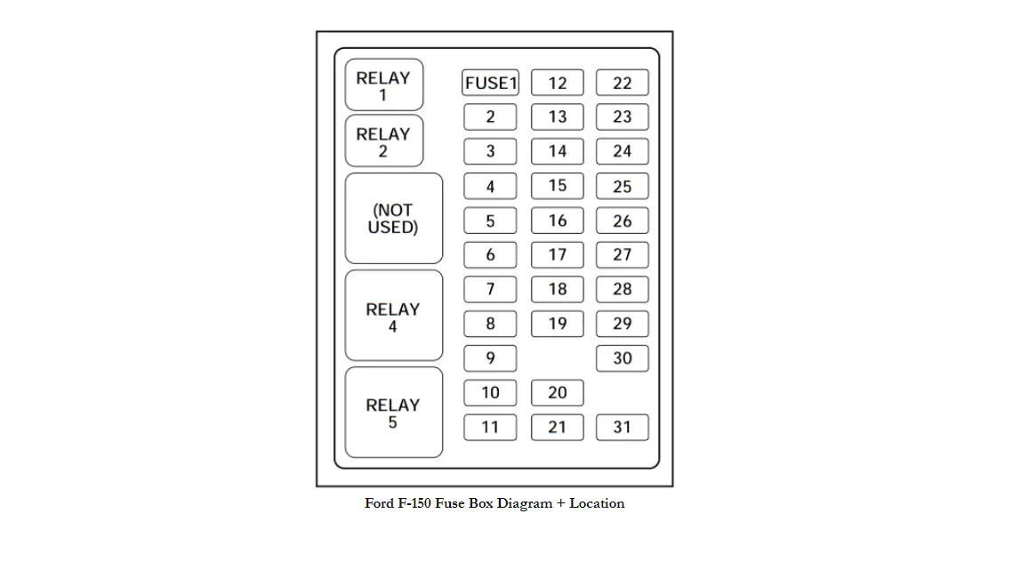
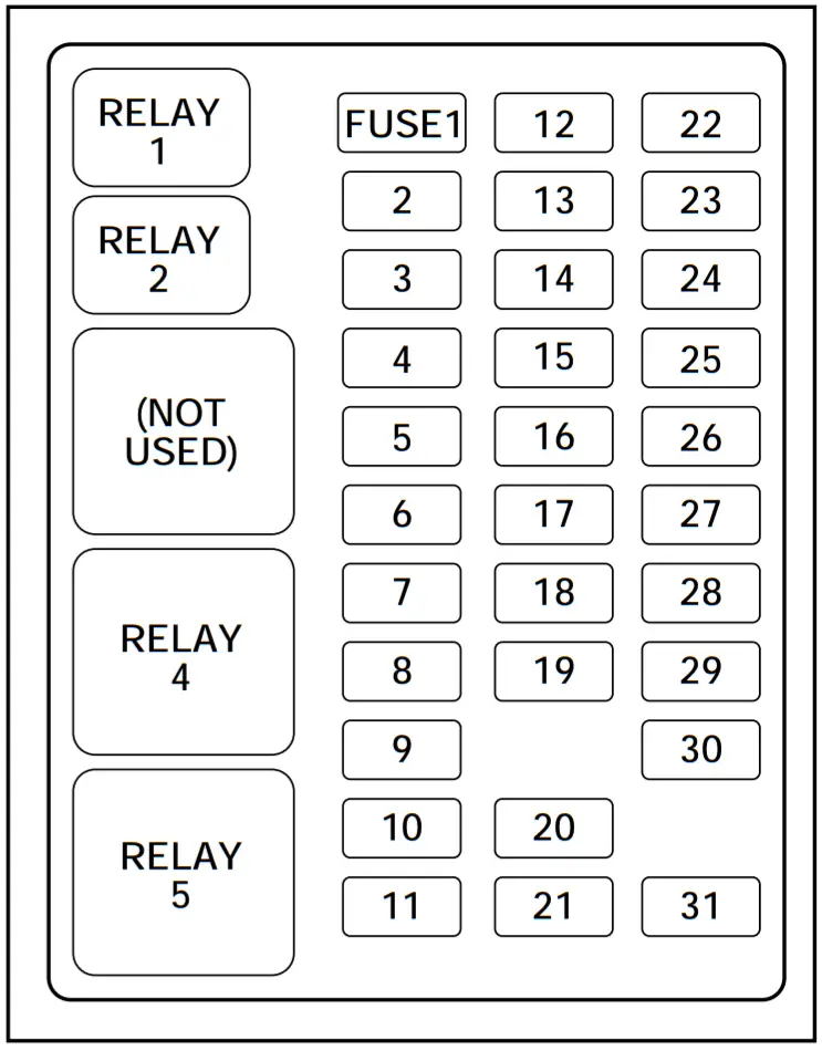
Location of the Fuse Box:
Below is the passenger compartment fuse panel diagram for 1997-2004 Ford F-150 pickup trucks. The fuse panel is located to the left of the steering wheel, near the brake pedal. Once the panel is removed, it will expose the fuse box, spare fuses, and relays.
See also: Ford F-150 Recalls
Other top manuals:
- THETFORD Triplex 700 Series Cooker User Manual
- THETFORD SOG52 Series Oven Grill Installation Guide
- THETFORD 440-700 Series Cooker Installation Guide
| Number | Ampere rating [A] | Description |
| 1 | 15 | Audio |
| 2 | 5 | Powertrain Control Module (PCM), Cluster |
| 3 | 20 | Cigar lighter, Data link connector |
| 4 | 5 | 2000-2004: Power mirror switch, Mirror turn signal relays |
| 15 | 1997-1999: Autolamp Module, Remote Entry Module, Mirrors | |
| 5 | 15 | Speed control module, Reverse lamp, Climate mode switch, Daytime Running Lamps (DRL) relay, Digital Transmission Range (DTR) sensor (2001-2004), AC Clutch Relay (1997-1999) |
| 6 | 5 | Cluster, Brake shift interlock solenoid, GEM, Rear Air Suspension Module (1997-1999) |
| 7 | — | — |
| 8 | 5 | Radio, Remote entry module, GEM, In-vehicle entertainment system (SuperCrew only) |
| 9 | — | — |
| 10 | — | — |
| 11 | 30 | Front washer pump relay, Wiper run/park relay, Wiper HI/LO relay, Windshield wiper motor |
| 12 | — | — |
| 13 | 20 | Stop lamp switch (Lamps), Turn/Hazard flasher, Speed Control Module (1997-2000) |
| 14 | 15 | Battery saver relay, Interior lamp relay, Accessory Delay Relay (Power Windows) (1997-2000) |
| 15 | 5 | Stop lamp switch (speed control, brake shift interlock, ABS (1997-2000), PCM Module Inputs (1997-2000)), GEM, Rear Anti-lock Brake System (RABS) module |
| 16 | 20 | Headlamps (hi beams), Cluster (hi beam indicator) |
| 17 | — | — |
| 18 | 5 | Instrument illumination (dimmer switch power) |
| 19 | — | — |
| 20 | 5 | Audio, GEM, Powertrain Control Module (PCM), Transmission range sensor |
| 21 | 15 | Clutch switch, Starter relay, I/P fuse 20, Digital Transmission Range (DTR) Sensor (2001-2004) |
| 22 | 10 | Air bag module, Passenger air bag deactivation module |
| 23 | 10 | Trailer tow battery Charge relay, Turn/Hazard flasher, 4×4 solenoids, 4×4 relays, Overhead console, 4-Wheel Anti-lock Brake System (4WABS) module, EC mirror, Heated seats |
| 24 | 10 | 2001-2004: Function selector switch assembly 1997-1999: Climate Mode Switch (Blower Relay) |
| 25 | 10 | 2003-2004: Heated mirrors |
| 5 | 1997-1999: 4 Wheel Anti-Lock Brake System (4WABS) Module | |
| 26 | 10 | Right-hand low beam headlamp |
| 27 | 5 | Foglamp relay and foglamp indicator, Main light switch (upstream) (2001-2004) |
| 28 | 10 | Left-hand low beam headlamp |
| 29 | 5 | Autolamp module, Transmission overdrive control switch, Central security module (2001-2004), Beltminder (2001-2004) |
| 30 | 30 | Passive Anti-theft transceiver, Cluster, Ignition coils, PCM relay, Coil on plugs (2001-2004), Radio noise capacitor (2001-2004), ECC diode (2001-2004) |
| 31 | — | — |
| Relay | |
| R1 | Interior lamp relay |
| R2 | Battery saver relay |
| R3 | — |
| R4 | One-touch down window relay |
| R5 | Accessory delay relay |
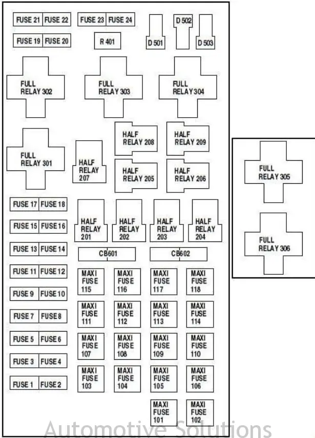
Ford F-150 Power Distribution Box (Option 1)
The power distribution box is located in the engine compartment and contains high-current fuses as well as relays. These larger fuses help to protect your vehicle’s main electrical systems from overloads.
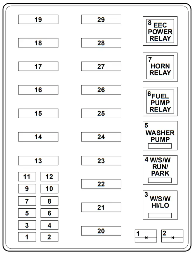
Ford F-150 Power Distribution Box (Option 2)
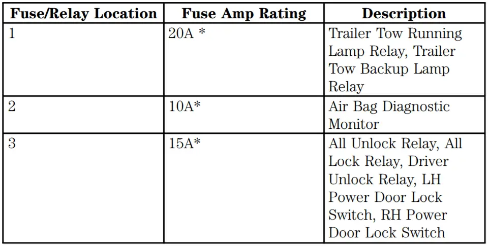
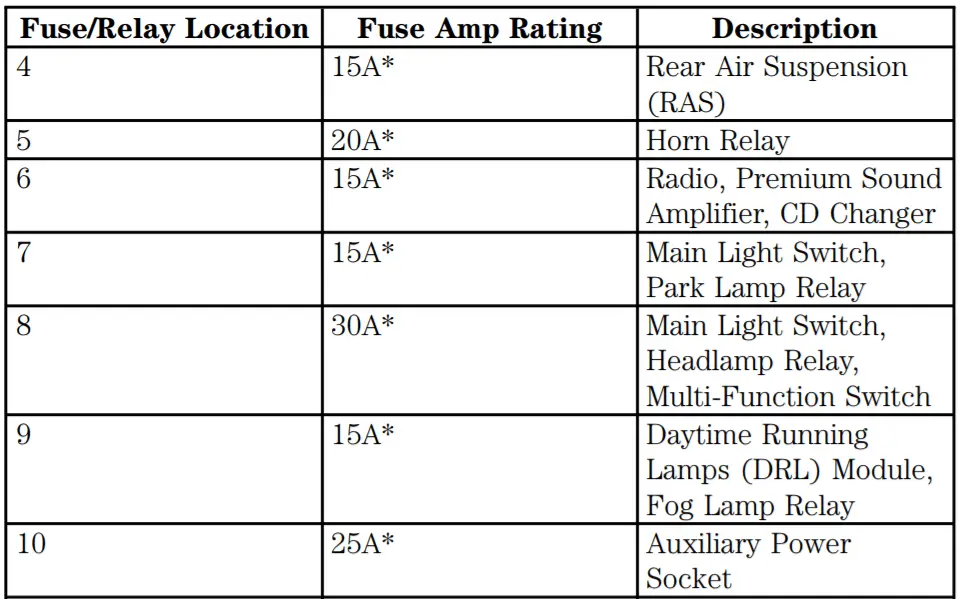
| Number | Ampere rating [A] | Description |
| 1 | 20 | Power point |
| 2 | 30 | Powertrain Control Module (PCM) |
| 3 | 30 | Main light switch, Headlamp relay, Multifunction switch |
| 4 | 20 | Console power point (Harley Davidson only) |
| 15 | 1997-1999: Air Suspension | |
| 5 | 20 | Trailer tow back-up/park lamps |
| 6 | 15 | Main light switch, Park lamp relay |
| 7 | 20 | Horn |
| 8 | 15 | Power door locks, Central Security Module (CSM) (2001-2004), Lock relays (not used on SuperCrew) (2001-2004) |
| 9 | 15 | Daytime Running Lamps (DRL), Fog lamps |
| 10 | 20 | Fuel pump |
| 11 | 20 | Alternator field |
| 12 | 20 | 2000-2004: Rear auxiliary power point |
| 13 | 15 | 2000-2004: A/C clutch |
| 14 | — | — |
| 15 | 10 | 2001-2004: Running board lamps |
| 16 | 15 | 2003-2004: Bi-fuel injector module, fuel selector switch and alternative fuel injectors (Bi-fuel vehicles only) |
| 17 | — | — |
| 18 | 18 | PCM, Fuel injectors, Fuel pump relay, Mass air flow sensor |
| 19 | 10 | Trailer/Camper adapter (right stop/tum lamp) |
| 20 | 10 | Trailer/Camper adapter (left stop/turn lamp) |
| 21 | — | — |
| 22 | — | — |
| 23 | 15 | HEGO sensor, Automatic transmission (2000-2004), Canister Vent (1997-2000), Powertrain Control Module (1997-1999), CMS Sensor (2000) |
| 24 | 15 | 1997-1999: Powertrain Control Module, Automatic Transmission, CMS Sensor |
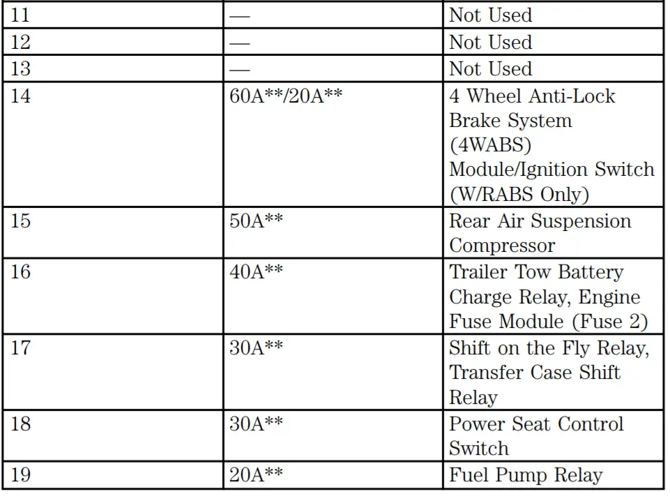
| 101 | 30 | Trailer tow battery charge |
| 102 | 50 | Four-wheel Anti-lock Brake System (4WABS) module |
| 20 | Rear-wheel Anti-lock Brake System (RABS) module, Ignition switch | |
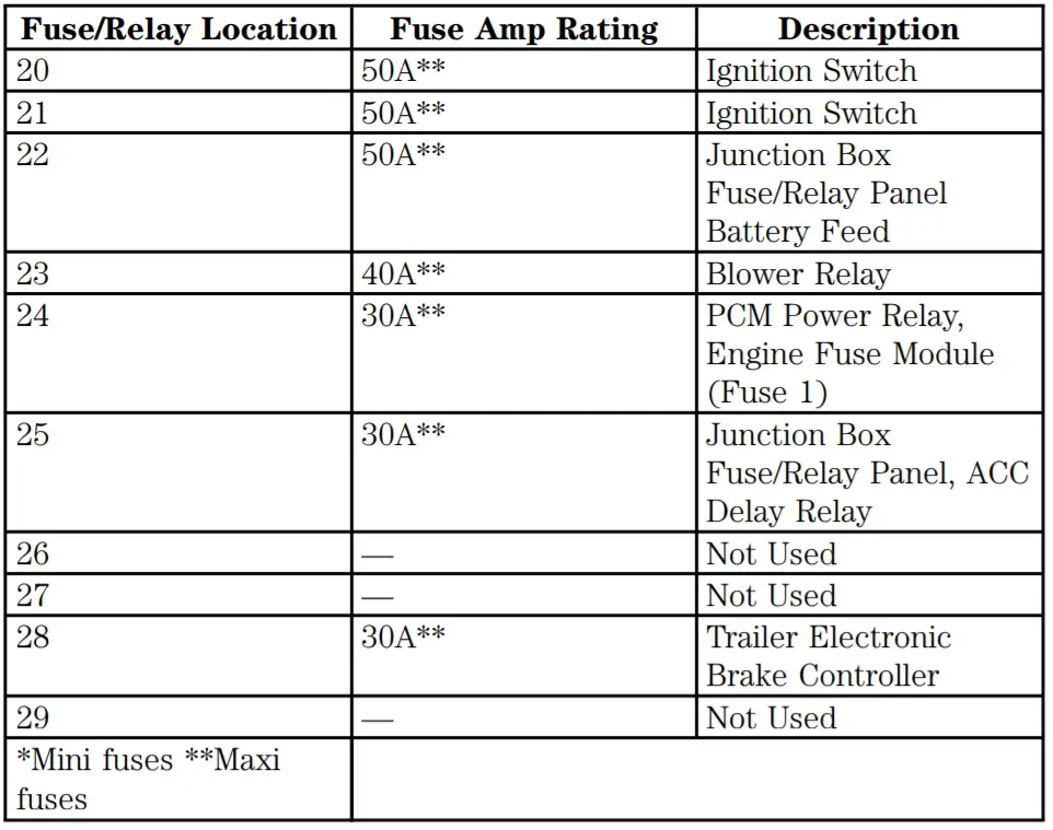
| 103 | 50 | Central junction box |
| 104 | 30 | 4×4 shift motor & clutch |
| 105 | 40 | Climate control front blower |
| 106 | 20 | 2000-2004: Intercooler pump (supercharged engine only) |
| 107 | — | — |
| 108 | 30 | Trailer tow electric brake |
| 109 | 50 | 1997-1999: Air Suspension Compressor |
| 110 | 30 | 2001-2004: Accessory delay relay (Not used on SuperCrew) 1997-2000: Power Windows |
| 111 | 40 | Ignition switch battery feed (start and run circuits) |
| 112 | 30 | Drivers power seat, Adjustable pedal switch (2000-2004) |
| 113 | 40 | Ignition switch battery feed (run and accessory circuits) |
| 114 | — | — |
| 115 | 20 | 2000-2004: Power door locks (SuperCrew only) |
| 116 | 40 | 2003-2004: Heated backlight |
| 117 | — | — |
| 118 | 30 | 2001-2004: Heated seats |
| Circuit Breaker | |
| 601 | 2000-2004: Power windows, Moonroof (SuperCrew only) |
| 602 | — |
| Relay | |
| 201 | Trailer tow park lamp relay |
| 202 | Front wiper run/park relay |
| 203 | railer tow backup lamp relay |
| 204 | A/C clutch relay |
| 205 | Horn relay |
| 206 | Fog lamp relay |
| 207 | Front washer pump relay |
| 208 | 2000-2004: Intercooler pump relay (supercharged engine only) |
| 209 | Front wiper HI/LO relay |
| 301 | Fuel pump relay |
| 302 | Trailer tow battery charge relay |
| 303 | 2003-2004: Heated backlight relay (SuperCrew only) 1997-1999: Rear Air Suspension Relay |
| 304 | Powertrain Control Module Relay |
| 305 | 2000-2004: Fuel pump HI/LO relay (supercharged engine only) |
| 306 | 2000-2004: Inertia switch relay (supercharged engine only) |
| 401 | — |
| Diode | |
| 501 | Powertrain Control Module Diode |
| 502 | A/C compressor diode |
| 503 | — |

![]()


