

BOBRICK B-9806 Straight Grab Bar Instruction Manual
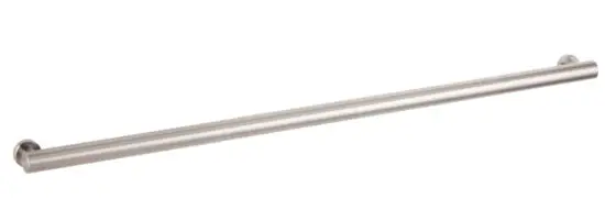
B-9806 and B-9807
NOTE:
For Installation on
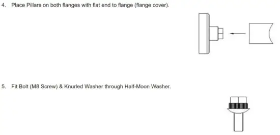
a. Dry-Walls
b. Glass-Partitions and Metal Partitions as well as
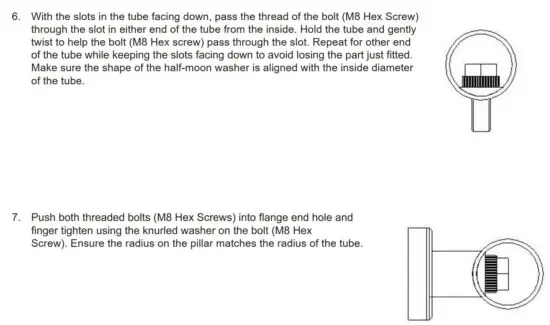
c. “back-to-back-installation of two grab bars against each other from opposite sides of partition-panels (glass and any other partition material)
Please see separate installation instructions of respected installation kits.
Required Tools
a. Spanner (preferably ring end) 13mm (similar to ½”)
b. Laser/Spirit level
c. Phillips head screwdriver
d. six pcs. #10 sheet metal screws, flat head, stainless steel, length depending on application (e.g. 1/2″ length for 1/2″ CL-partitions and 1” length for 1” thick particle board)
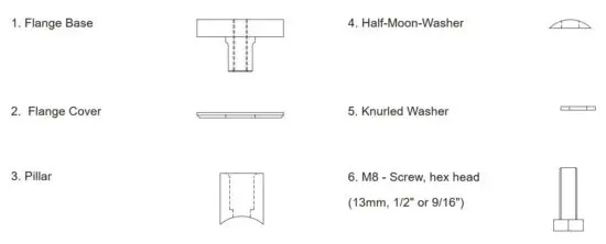
“Exploded” overview of the grab bar flange
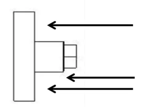
- Securely fix flange-bases to panel/wall at correct pitch
(18″/24″/36″/42″) using the appropriate fixings (see also PCD-Pitch
Circle diameter). Ensure a minimum of 6″ from corners/returns so that
a spanner can be used later. - Use base flange as a template to mark drilling holes on the wall with a
pencil.
Base flange has 3 pcs. of 5.0mm (3/16″) mounting holes, equally spaced 120° apart on a 38.0mm (1-1/2″) Bolt/Pitch Circle Diameter (BCD/PCD).
Bobrick recommends using #10 Sheet metal screws, flat head, length depending on application. Screw heads want to be below flush. Use a level to assist in laying out.
Screw- and drilling examples :
a. #10 sheet metal screw, flat head, 1/2″ screw length for 1/2″ CL-partitions, 3/16″ predrill
b. #10 sheet metal screw, flat head, 1″ length for 1″ thick particle
3. Fit the flange covers on both flanges with the bevelled edge facing out.
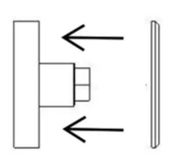
Tighten both ends with the ring end of a 13mm spanner making sure not to damage the tube with the spanner.
Fit end caps making sure to locate the screwdriver release recess facing down out of casual observation.

2021 by Bobrick Washroom Equipment, Inc.
Form No. 9806-9807-75_ii Issued 6/21/21 Printed in U.S.A.
In the U.S.A.: BOBRICK WASHROOM EQUIPMENT, INC.
Los Angeles: 6901 Tujunga Ave., North Hollywood, CA 91605-6213: Tel: (818) 982-9600, FAX: (818) 503-1102
New York: 200 Commerce Drive, Clifton Park, NY 12065-1350; Tel: (518) 877-7444, FAX: (518) 877-5029,
or e-mail: [email protected]
In Canada: BOBRICK WASHROOM EQUIPMENT COMPANY
45 Rolark Drive, Scarborough, Ontario M1R 3B1 • Eastern Canada: Tel: (877) 423-6555 • FAX: (877) 423-8555
Western Canada: Tel: (877) 423-6444 • FAX: (877) 423-8444
Read More About This Manual & Download PDF:


