
![]() 4512710 Z-Wave Dimmer 400w
4512710 Z-Wave Dimmer 400w
Installation Guide![]()
Important: Read All Instructions Prior to Installation
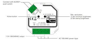
Function introduction
Product Data
| Z-Wave Frequency | 868.42 MHZ (EU)/869.0 MHZ (RU)/908.42 MHz (US) |
| Input Voltage | AC100-240V |
| Output Voltage | AC100-240V |
| Output Current | 1.8A max. |
| Allowed Inrush Current | Cold Start 75A max. |
| Operating temperature | 0 to 40°C |
| Relative humidity | 8% to 80% |
| Dimensions | 45.5x45x20.3mm |
| Load Symbol | Load Type | Maximum Load | Remarks |
| Dimmable LED lamps | 200W @ 220V | Due to the variety of LED lamp designs, a maximum number of LED lamps is further dependent on power factor results when connected to dimmer. | |
| Dimmable LED drivers | 200W @ 220V | The maximum permitted number of drivers is 200W divided by driver nameplate power rating. | |
| Incandescent lighting, HV Halogen lamps | 400W @ 220V | ||
| Low voltage halogen lighting with electronic transformers | 200W @ 220V |
Safety & Warnings
- DO NOT install with power applied to the device.
- DO NOT expose the device to moisture.
Quick Start
How to install:
- Step 1: power on the Z-Wave in-wall dimmer.
- Step 2: activate inclusion mode on your Z-Wave controller.
- Step 3: activate the inclusion mode of the dimmer by triple pressing the action button on the dimmer. The dimmer will be included in the Z-Wave network.
Product Description
The in-wall dimmer is a Z-Wave device that is used to switch ON/OFF and adjust the light intensity of the connected light and can be controlled by other Z-Wave devices. The In-wall Dimmer can be included and operated in any Z-Wave network with other Z-Wave certified devices from other manufacturers and/or other applications. All non-battery-operated nodes within the network will act as repeaters regardless of vendor to increase the reliability of the network.
The encryption mode that the dimmer supports is S2 Unauthenticated. When the dimmer is being included in a ZWave network, you can use your primary controller/gateway to enable encryption mode or disable encryption. (The primary controller/gateway shall support encryption mode configuration). The dimmer supports OTA and can update firmware wirelessly.
Installation Guide
Please read carefully the enclosed user manual before installation of the in-wall dimmer, in order to ensure error-free functioning.
- Set minimum brightness: press and hold down the button for 3 seconds, when the current brightness value is 1%-50%, it will be set as minimum brightness. When the current brightness value is 0% or over 50%, the previously set minimum brightness will be deleted.
- Set startup brightness: short press the button twice, when the current brightness value is 1%-99%, it will be set as startup brightness. When the current brightness value is 0%, the previously set startup brightness will be deleted.
ATTENTION: Prior to the assembly of the product, the voltage network has to be switched OFF and ensured against reswitching.
Inclusion (adding to a Z-Wave network)
- Set primary controller/gateway into inclusion mode (Please refer to your primary controller’s manual on how to turn your controller into inclusion).
- Power on the in-wall dimmer and set it into inclusion mode. There are two methods to set the in-wall dimmer into inclusion mode:
1. Repower on the dimmer, it will be set into inclusion mode automatically and waiting to be included.
2. Triple press the action button on the dimmer, it will set the dimmer into inclusion mode.
The connected light will stay solid for 3 seconds to indicate successful inclusion.
Exclusion (removing from a Z-Wave network)
There are two exclusion methods:
Method 1: Exclusion from the primary controller/gateway as follows:
- Set the primary controller/gateway into exclusion mode (Please refer to your primary controller’s manual on how to set your controller into exclusion).
- Triple press the action button, the dimmer will be set to exclusion mode, and waiting to be excluded, then the dimmer will be excluded from the network.
Method 2: Factory reset the dimmer will force it to be excluded from a network. (please refer to the part “Factory Reset” of this manual)
Note: Factory reset is not recommended for exclusion, please use this procedure only if the primary controller/gateway is missing or otherwise inoperable.
Factory Reset
Press and hold down the action button for over 10 seconds, the dimmer will be reset to factory defaults.
Association
Z-Wave devices control other Z-Wave devices. The relationship between one device controlling another device is called association. In order to control a different device, the controlling device needs to maintain a list of devices that will receive controlling commands. These lists are called association groups and they are always related to certain events (e.g. button pressed). In case the event happens all devices stored in the respective association group will receive a common wireless command.
Association Groups:
| Association Groups | Group Name | Max Nodes | Description |
| Group 1 | Lifeline | 5 | 1. When the factory reset the dimmer, send ‘Device Reset Locally Notification CC” to associated devices of this group to report factory reset information. 2. When load state changes, send ‘Basic Report CC’ to associated devices of this group. 3. When a load malfunction is detected, send “Emergency shutoff status” to Lifeline. |
Set and unset associations:
(Note: All association information will be cleared automatically once the dimmer is excluded from a network.)
Set association by operating primary controller/gateway to send packets to the dimmer:
The primary controller/gateway sends packets to the dimmer using “Command Class ASSOCIATION”
Operating the device
Short press the action button on the dimmer to switch ON/OFF the load.
Node Information Frame
The Node Information Frame is the business card of a Z-Wave device. It contains information about the device type and the technical capabilities. The inclusion and exclusion of the device is confirmed by sending out a Node Information Frame. Besides this, it may be needed for certain network operations to send out a Node Information Frame.
How to send out Node Information Frame:
When the dimmer is set to inclusion/exclusion mode again, it will send out Node Information Frame, there are 2 kinds of operation as follows:
- triple press the action button, the dimmer will be set to inclusion/exclusion mode, then send out Node Information Frame.
- When the dimmer is under inclusion mode, there are two kinds of operation:
1. Triple press inclusion/exclusion button, the dimmer will be set to inclusion mode again, and send out Node Information Frame.
2. Power off and power on the dimmer, it will be set to inclusion mode automatically, and send out Node Information Frame.
Technical Data
| Wireless Range | up to 100 m outside, on average up to 40 m inside buildings |
| SDK | 6.71.03 |
| Explorer Frame Support | Yes |
| Device Type | Light Dimmer Switch |
| Generic Device Class | GENERIC_TYPE_SWITCH_MULTILEVEL |
| Specific Device Class | SPECIFIC TYPE POWER SWITCH MULTILEVEL |
| Role Type | Always On Slave (AOS) |
| Routing | Yes |
SUPPORTED COMMAND CLASS
| Node Info | Security Command Supported Report | ||
| COMMAND_CLASS_ZWAVEPLUS _INFO | V2 | COMMAND_CLASS_MANUFACTURER_SPECIFIC | V2 |
| COMMAND_CLASS_TRANSPORT_SERVICE | V2 | COMMAND_CLASS_VERSION | V2 |
| COMMAND_CLASS_SECURITY | V1 | COMMAND_CLASS_SWITCH_MULTILEVEL | V4 |
| COMMAND_CLASS_SECURITY_2 | V1 | COMMAND_CLASS_SCENE_ACTIVATION | V1 |
| COMMAND_CLASS_SUPERVISION | V1 | OMMAND_CLASS_SCENE_ACTUATOR_CONF | V1 |
| COMMAND_CLASS_NOTIFICATION | V8 | ||
| COMMAND_CLASS_CONFIGURATION | V2 | ||
| COMMAND_CLASS_ASSOCIATION_GRP_INFO | V3 | ||
| COMMAND_CLASS_ASSOCIATION | V2 | ||
| COMMAND CLASS FIRMWARE UPDATE MD | V4 | ||
| COMMAND_CLASS_POWERLEVEL | V1 | ||
| COMMAND_CLASS_DEVICE_RESET_LOCALLY | V1 | ||
Notification Command Class
The dimmer supports Emergency shut off, when the inside temperature is over 90℃ and is detected by the built-in distance, the dimmer will send out Emergency shutoff status to Lifeline.
| Notification Type | Notification |
| System (0x09) | Emergency shutoff status (0x07) |
Configuration Command Class
| Parameter | Size | Description | Default Value | |
| 2 | 1 | Info: Saving load state before power failure 0 – shutoff load 1 – turn on the load 2 — save load state before power failure | 0 | |
| 3 | 1 | Info: Enable/disable to send the basic report to the Lifeline when the load state changed (When the value set as 1, re-power on the dimmer, it will send the Basic report automatically) 0 – Disable to send Basic report 1 – Enable to send Basic report | 1 | |
| 4 | 1 | Default fade time (uni is second, this value has the same function as Duration of Multilevel) Valid value: 0-OxFF | 1 | |
| Value | Description | |||
| Ox00 | Instantly | |||
| Ox01..0x7F | 1 second (0x011 to 127 seconds (0x7F) in 1 second resolution. | |||
| Ox80..0xFE | 1 minute (0x80) to 127 minutes (OxFE) in 1 minute resolution. | |||
| OxFF | Factory default duration. I second ) | |||
| 5 | 1 | Setting minimum brightness value Valid value: 0-50, the bigger the value is, the higher the load’s minimum brightness is | 5 | |
| 6 | 1 | Choose MOSFET driving type 0 – trailing edge 1 – leading edge | 0 | |
| 7 | 1 | Enable/disable external switch to be added to and removed from a network (when enables this function, triple press the external switch within 1.5 seconds to be added to or removed from a network) 0 – disable 1 – enable | 1 | |
| 8 | 1 | Setting dimming curve 0 – linear dimming 1 – logarithmic dimming | 0 | |
| 9 | 1 | Setting startup brightness of the load Valid value: 0~99 Note: every time when turn on the load from OFF status, if the target brightness is lower than the startup brightness, the brightness will first go to the startup brightness value then fall down to the target brightness | 0 | |
Note:
- The max. allowed inrush current of this dimmer is cold start 75A, when connecting LED drivers or LED luminaries in parallel, please make sure that the total inrush current of the parallel-connected drivers or luminaries do not exceed the max. allowed inrush current of this dimmer.
- The recommended number of parallel-connected drivers or luminaries shall not be more than 10, otherwise, the dimmer may be damaged due to the high inrush current at the moment of starting.
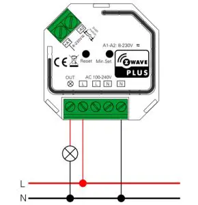
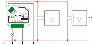
Wiring Diagram
- Connection without Push switch

- Connection with Push

Importer:
Namron AS Nedre kalbakkvei 88B
1081 Olso Norway
Made in China


 Instructions")