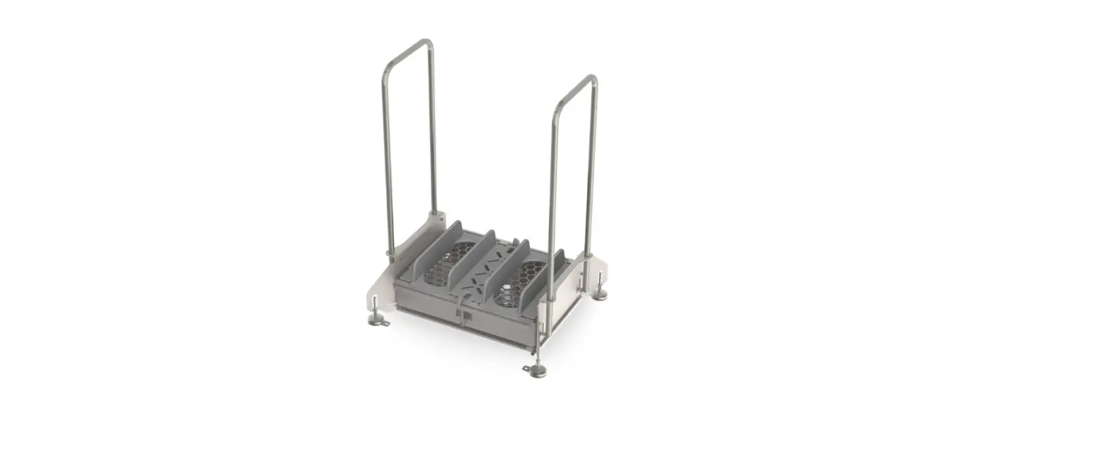
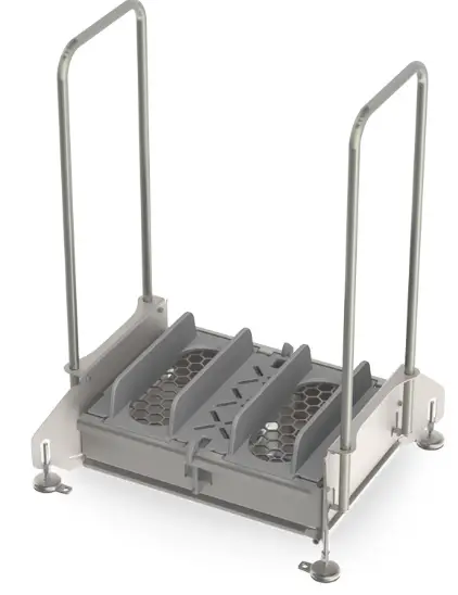
FOAMit SS2-FMH Footwear Sanitation System
READ ALL INSTRUCTIONS BEFORE OPERATING EQUIPMENT
WARNING
Read this manual completely and understand the machine before operating or servicing it.
- Read all instructions before operating or interacting with this unit.
- Always wear appropriate personal protective equipment (PPE) when operating or servicing unit.
- Always follow all chemical safety precautions and handling instructions provided by the chemical manufacturer and Safety Data Sheet (SDS).
- If this unit is modified or serviced with parts not listed in this manual, the unit may not operate correctly.
- This unit is for use with fully protective footwear only.
- Chemical Spray Hazard
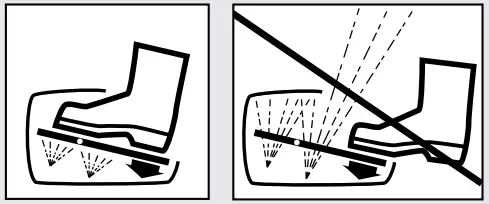
- Insert foot fully into unit and press down with heel. Partial insertion may cause chemical spray to face and eyes.
- Wear splash goggles when required by chemical manufacturer, SDS, or OSHA.
- Do not remove or modify spray guard.
- Always disconnect the unit from compressed air before performing any maintenance.
- Do not exceed an incoming air pressure of 130psi (8.9 bar).
- Do not exceed a fluid temperature of 100˚F (37˚C).
- Never use unit with hydrocarbons.
PROTECT THE ENVIRONMENT
Please dispose of packaging materials, old machine components, and hazardous fluids in an environmentally safe way according to local waste disposal regulations.
- Always remember to recycle.
- Specifications and parts are subject to change without notice.
INTENDED USE
This machine is designed to help sanitize footwear at transition zones with a focus on reduced moisture. This machine is intended to sanitize shoe soles and not intended for any other use.
| OPTIONS | ||
| System Add-On | ||
| SS2 | – | None (standard) |
| Floor mounted handle (FMH) | ||
| Manual boot scrubber (MBS) | ||
| Add bold option codes to item number as shown. For standard options, no option code is needed. Examples: • SS2 (standard unit) • SS2-FMH (unit with floor mounted handle) • SS2-MBS (unit with manual boot scrubber) | ||
READ ALL INSTRUCTIONS BEFORE OPERATING EQUIPMENT
| REQUIREMENTS | |
| Compressed air requirements | 40-60 psi (2.8-4.1 bar) with 1 cfm (28.3 l/min) |
| Recommended operating air pressure | 40 psi (2.8 bar) with 1 cfm (28.3 l/min) |
| Liquid temperature range | 40-100˚F (4-37˚C) |
| Chemical compatibility | Chemical products used with this equipment must be formulated for this type of application and compatible with unit materials and pump seals. For more information on chemical compatibility, consult the manufacturer or SDS for your product or contact our Tech Support department. |
| SPECIFICATIONS | |
| Power type | Compressed air |
| Chemical pickup type | Draws from pre-mixed product |
| Number of products unit can draw from | One product |
| Suction line length/diameter | 3 ft. (0.9 m) clear hose with 1/4 in. (6.4 mm) inside diameter |
| Output volume* | 0.2 oz. (5.9 mL) per spray |
| Pump seals | Viton |
| Number of nozzles | 4 nozzles |
| Dimensions (LxWxH) | SS2: 24.7x11x18 in. (62.7×27.9×45.7 cm) approximately SS2-FMH: 27.1×15.7×41.5 in. (68.9×39.9×105.4 cm) approximately SS2-MBS: 28.7×29.2×40.3 in. (72.9×74.2×102.4 cm) approximately |
| Weight | SS2: 24 lbs (10.9 kg) approximately FMH: 16 lbs (7.3 kg) approximately, SS2-FMH: 40 lbs (18.1 kg) approximately MBS100-C: 34 lbs (15.4 kg) approximately, SS2-MBS: 58 lbs (26.3 kg) approximately |
| Noise level | Less than 70 dB(A) |
- Dilution rates and flow rates given are based on chemical with viscosity of water and factory air pressure settings.
LIFT POINTS
INSTRUCTIONS
Installation Instructions
For SS2 Unit:
- Position footwear sanitizing unit in desired location.
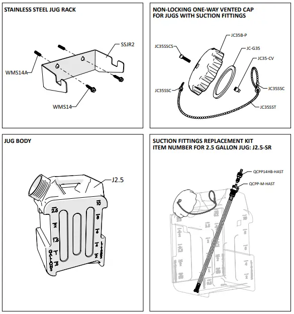
- If desired, mount the chemical jug to the wall using the provided mounting hardware (WMS14, WMS14A) and rack (SSJR2). The chemical jug should not be mounted higher than 30 in. (0.7 m) above the unit. Suction hose length should not exceed 8 ft. (2.4 m).
- Connect an air line to the air fitting (AP25).
- Follow all instructions from chemical manufacturer. Fill the chemical jug (J2.5BKSR) with pre-mixed or ready-to-use chemical solution and connect the suction line to the jug suction fitting.
- Prime the unit according to the Priming Instructions.
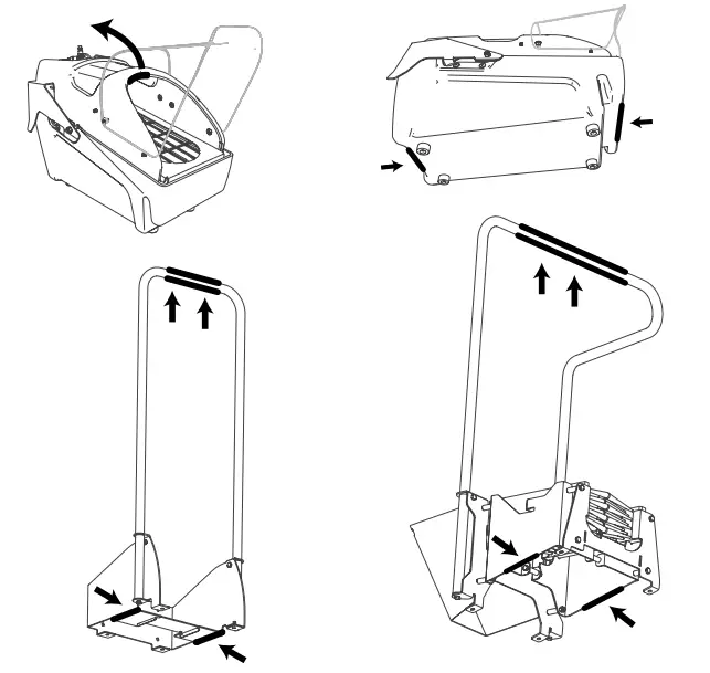
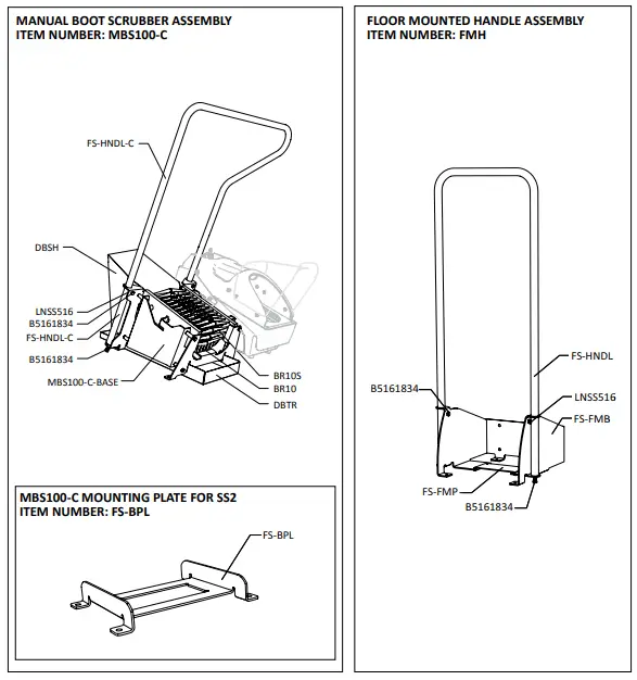
For SS2-FMH Unit
- Select desired location to mount footwear sanitizing unit.
- Attach handle (FS-HNDL) to handle bracket (FS-FMB) with bolts (B5161834) on the ends. Secure with set screws (B5161834 and LNSS516).
- Mount handle assembly to floor or wall (hardware not included).
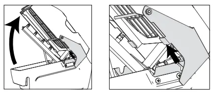
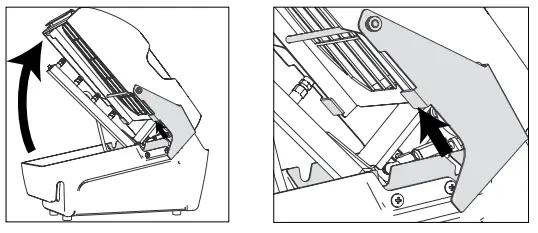
- Lift up on the shroud (SS2-SH), rotate the top half of the unit, and slide top half of unit from the bracket (FS-GUARD) to release from the base.

- 5. Hook the plate (FS-FMP) on the underside of the collection basin to the bracket at the base of the mounting handle.

- If desired, mount the chemical jug to the wall using the provided mounting hardware (WMS14, WMS14A) and rack (SSJR2). The chemical jug should not be mounted higher than 30 in. (0.7 m) above the unit. Suction hose length should not exceed 8 ft. (2.4 m).
- Connect an air line to the air fitting (AP25).
- Follow all instructions from chemical manufacturer. Fill the chemical jug (J2.5BKSR) with pre-mixed or ready-to-use chemical solution and connect the suction line to the jug suction fitting.
- Prime the unit according to the Priming Instructions.
For SS2-MBS Unit
- Select desired location to mount footwear sanitizing system.
- Attach handle (FS-HNDL-C) to boot scrubber base (MSC100-C-BASE) with bolts (B5161834) on the ends. Secure with set screws (B5161834 and LNSS516).
- Slide debris tray (DBTR) under boot scrubber, lift up and hook tray into slots on front of the boot scrubber frame to secure.
- Connect debris shield (DBSH) by sliding hooks into the slots on the back the boot scrubber frame. Note: Brushes (BR10S) must be removed before installing/uninstalling debris shield.
- Position boot scrubber in desired location and mount to floor (hardware not included).
- Position mounting bracket (FS-BPL) for footwear sanitizer next to the boot scrubber and secure to the floor (hardware not included).
- Hook the plate (FS-FMP) on the underside of the collection basin to the mounting bracket (FS-BPL).

- If desired, mount the chemical jug to the wall using the provided mounting hardware (WMS14, WMS14A) and rack (SSJR2). The chemical jug should not be mounted higher than 30 in. (0.7 m) above the unit. Suction hose length should not exceed 8 ft. (2.4 m).
- Connect an air line to the air fitting (AP25).
- Follow all instructions from chemical manufacturer. Fill the chemical jug (J2.5BKSR) with pre-mixed or ready-to-use chemical solution and connect the suction line to the jug suction fitting.
- Prime the unit according to the Priming Instructions.
WARNING: Chemical Spray Hazard
- Insert foot fully into unit and press down with heel. Partial insertion may cause chemical spray to face and eyes.
- Wear splash goggles when required by chemical manufacturer, SDS, or OSHA.
- Do not remove or modify spray guard.

Priming Instructions:
Note: This unit is for use with fully protective footwear only. Do not activate the unit if a user’s foot is not positioned inside the spray guard (SS2-SH).
- Verify that the chemical jug (J2.5BKSR) is full, and connect the jug to the unit suction line. Check all tubing connections and verify that none are loose or leaking.
- Place foot on the grate (FS-GRATE) and step down with heel 10-15 times or until all air has been purged from the suction line.
- Check bottom of footwear for proper sanitizer application. The entire sole should be covered with a consistent spray pattern.
Operation Instructions
For SS2 Unit:
- Place one foot on the grate (FS-GRATE) and step down with heel to activate the spray.
- Repeat the process with your other foot.
For SS2-FMH Unit:
- Grip the handle (FS-HNDL) with both hands to establish 3 points of contact.
- Place one foot on the grate (FS-GRATE) and step down with heel to activate the spray.
- Repeat the process with your other foot.
For SS2-MBS Unit:
- Grip the handle (MBS-HNDL) above the manual boot scrubber with both hands to establish 3 points of contact.
- Place one foot in the brushes and push foot back and forth to remove debris. Repeat the process with your other foot.
- Move to the footwear sanitizer and grip the handle (FS-HNDL) above with both hands to establish 3 points of contact.
- Place one foot on the grate (FS-GRATE) and step down with heel to activate the spray.
- Repeat the process with your other foot.
Maintenance Instructions
The unit should be cleaned regularly to ensure that it is in a clean condition. Cleaning schedule will depend on frequency of use and types of soils. Follow daily maintenance instructions to keep the unit clean; clean more often if necessary. Clean parts by any method suitable for the material type and safe for the facility environment. For example: use food-safe cleaner and food-safe material in a food processing facility. Always wear appropriate personal protective equipment (PPE) when operating or servicing unit.
Before performing any maintenance, disconnect the unit from the compressed air supply. After maintenance is complete, reconnect compressed air, verify suction line and fittings are secure, and re-prime the unit according to the Priming Instructions.
Daily Maintenance for SS2, SS2-FMH, and SS2-MBS Units:
- Inspect the stainless foot grate (FS-GRATE) and shroud (SS2-SH) for soil and wipe clean.
- Wipe clean the polycarbonate spray guard (SS2-SPGRD).
- The basin (SS2-H) should be emptied and cleaned each time the chemical supply container is changed or refilled. Follow instructions on how to clean collection basin
(SS2-H). - Verify that the nozzle assembly is free of any debris or blockage. Rinse with low pressure water if necessary.
- Inspect all tubing for leaks or excessive wear. Make sure all hose clamps and push fittings are in good condition and properly secured.
Daily Maintenance for SS2-MBS Unit Only:
- Remove brushes (BR10 and BR10S) by lifting them out from the brush bracket. Remove debris and clean. Brushes should be replaced every 6 months depending on wear.
- Slide out debris tray (DBTR). Empty debris and wipe clean.
- Lift up on debris shield (DBSH) to remove.
- Base assembly of the unit is fully stainless and can be cleaned in place by any method suitable for stainless steel.
How To Clean Collection Basin (SS2-H):
- Empty collection basin (SS2-H)
- Lift up on the shroud (SS2-SH), rotate the top half of the unit, and slide top half of unit from the bracket (FS-GUARD) to release from the base.

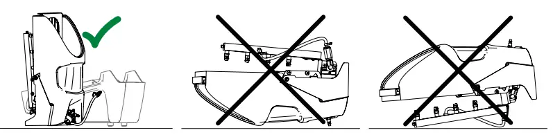
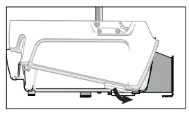
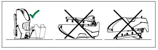
- Stand top half of unit on short end. Setting unit down in other position may cause damage to nozzle assembly.

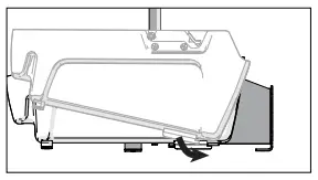
- Grab handle on front of collection basin and tip up to empty.
- Slide top half of unit back into place on collection basin.
- Lift up on the shroud (SS2-SH), rotate the top half of the unit, and slide top half of unit from the bracket (FS-GUARD) to release from the base.
Other Maintenance for SS2, SS2-FMH, and SS2-MBS Units:
- Inspect all parts of the unit regularly, and clean if necessary.
PARTS MATERIAL LIST
| DESCRIPTION | ITEM NUMBER | MATERIAL TYPE |
| Manifold | MN186 | PVC |
| Nozzles | FCN120 | PVDF |
| Checks | CV18MFSS | stainless steel |
| Mounting frame | FS-FRAME | stainless steel |
| Pump | PSS02 | polypropylene |
| Check valves | CV14M14B-R, CV14M14B-L | PVC |
| Shroud | SS2-SH | polyethylene |
| Spray guard | SS2-SPGRD | polycarbonate |
| Clear tubing | H14C, H38C | PVC |
| Red/Blue tubing | H14BU | polyurethane |
| Roller cam | RCA | stainless, nylon |
| Two-way air valve | SS1B2WV | brass body with stainless steam |
| Other metal fittings | N/A | stainless steel |
| Other plastic fittings | N/A | polypropylene |
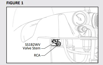
Troubleshooting Instructions
If footwear sanitizing unit will not spray:
- Check valve stem (SS1B2WV valve stem) and roller cam (RCA) to ensure proper movement and compression (Refer to Figure 1 below)
- If the pump is cycling, but the unit does not spray, the pump may be air locked.
- Check the suction line and strainer for debris and clean if necessary.

If footwear sanitizing unit sprays irregularly:
- Verify that the unit is connected to an appropriate compressed air source. This unit requires 40 psi (2.8 bar) with 1 CFM (28.3 l/min) to operate. To maximize unit lifespan and performance, compressed air should be clean and dry.
Note: If air source has a high moisture content, install a water separator (WS-20CFM) before the unit. - Verify the pump is cycling regularly. The pump can be disassembled and the o-ring can be relubricated with a silicone-based lube.
- Check the spray tips (FCN120) and make sure they are not clogged or blocked by debris. The spray tips may be removed and cleaned if necessary.
- Check hose clamps and ensure that barbs are secure.
- Check all tubing connections and verify that none are loose, broken, or leaking.
PARTS DIAGRAMS – UNITS WITH STANDARD FITTINGS
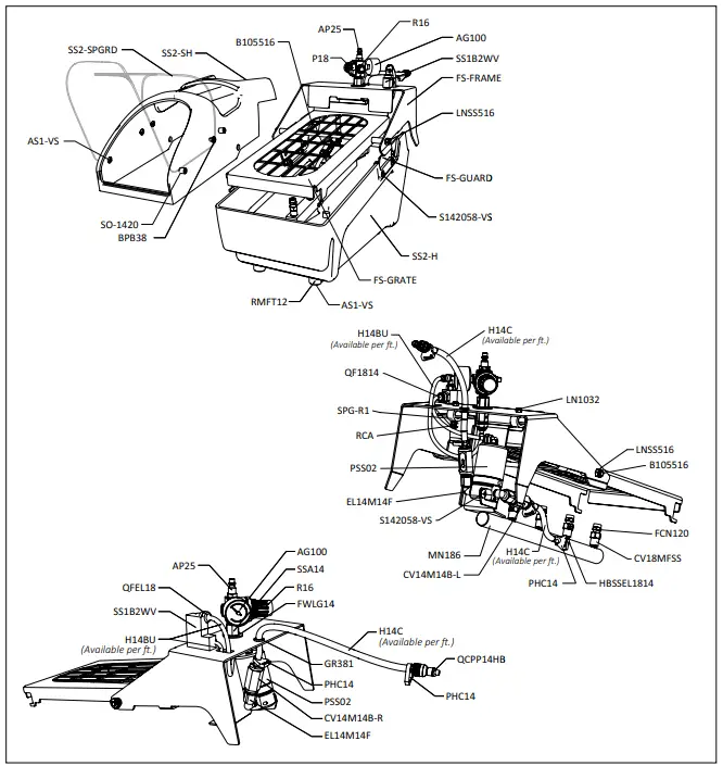
PARTS DIAGRAMS
PARTS LIST
| ITEM NUMBER | DESCRIPTION |
| AG100 | 1.5 INCH DRY MODEL 20 DUAL SCALE GAUGE |
| AP25 | AIR FITTING 1/4 MPT X PLUG-BRASS |
| AS1-VS | 1/4-20 X 1/2 PHIL TRUSS MACH SCREW 19-8 W/516 ORANGE VIBRASEAL PATCH |
| B105516 | BOLT-11.25 IN LONG-5/16 DIAMETER-18TPI |
| B5161834 | HEX HEAD 5/16-18 X 3/4 IN |
| BPB38 | BINDING POST BARREL – 3/8IN LONG – SS |
| BR10 | MBS SOLE BRUSH 10.5 X 3 – POLYPROPYLENE |
| BR10S | MBS SIDE BRUSH 12.5 X 3.44 – POLYPROPYLENE |
| CV14M14B-L | 1/4 MNPT X 1/4 BARB PVC CHK-302SS SPRING-VITON SEALS-AIR FLOW LEFT |
| CV14M14B-R | 1/4 MNPT X 1/4 BARB PVC CHK-302SS SPRING-VITON SEALS-AIR FLOW RIGHT |
| CV18MFSS | 1/8 MPT X 1/8 FPT SS CHECK VALVE-1 LB SS SPRING- VITON SEALS |
| DBSH | DEBRIS SHIELD FOR MBS100-C |
| DBTR | DEBRIS TRAY FOR MBS100-C |
| EL14M14F | 1/4 FPT X 1/4 MPT – POLYPRO ELBOW |
| FCN120 | FULL CONE NOZZLE-120 DEGREES-0.26GPM-PVDF |
| FS-BPL | BASE PLATE FOR MOUNTING SS2 TO FLOOR |
| FS-FMB | FLOOR MOUNT BRACKET FOR SS2 |
| FS-FMP | FLOOR MOUNT PLATE FOR SS2 (MOUNTS TO BOTTOM OF SS2) |
| FS-FRAME | STAINLESS HARDWARE MOUNTING FRAME FOR SS-2 |
| FS-GRATE | STAINLESS FOOT GRATE FOR SS2 |
| FS-GUARD | SS PIVOT PLATE FOR SS2 |
| FS-HNDL | HANDLE BAR FOR SS2 |
| FS-HNDL-C | HANDLE BAR FOR SS2-MBS COMBO |
| FWLG14 | .569 ID X 1.28 OD X .08 THICK FLAT WASHER SS 18-8 |
| GR381 | GROMMET-3/8IN ID, 5/8IN OD, 3/32IN Thick for 7/16IN Diameter Panel Hole |
| H14BU | 1/4in OD BLUE POLYURETHANE TUBING – Available per ft. |
| H14C | 1/4in ID (3/8 in OD) CLEAR POLYVINYL TUBING – Available per ft. |
| H38C | 3/8in CLEAR PVC TUBING – Available per ft. |
| HBSSEL1814 | STAINLESS HOSE BARB 1/8 MPT X 1/4 BARB ELBOW |
| J2.5 | 2.5 GALLON NATURAL JUG |
| J2.5-SR | 2.5 GALLON SUCTION FITTINGS REPLACEMENT KIT (SUCTION TUBE, COUPLER, PLUG) |
| JC35B | BLACK 3.5 INCH ONE WAY VENTED CAP POLYPROPYLENE WITH GASKET AND CHECK VALVE |
| JC35B-P | BLACK 3.5 INCH CAP – POLYPROPYLENE |
| JC35-CV | EPDM CHECK VALVE FOR NON LOCKING JUG CAP |
| JC-G35 | JUG CAP GASKET 3.5 INCH CAP EPDM |
| ITEM NUMBER | DESCRIPTION |
| JC35SSC | 304 SS END COUPLING FOR SIZE 8-10, ROUND BEAD CHAIN |
| JC35SSCS | SOCKET HEAD CAP SCREW-10-32 MPT-3/4IN LONG- VENTED |
| JC35SST | ROUND BEAD CHAIN, TYPE 304 STAINLESS STEEL, #10 |
| LN1032 | LOCKNUT 10-32 NPT |
| LNSS516 | 5/16-18 HEX NYLON INSERT LOCKNUT 18-8 PLN NE |
| MBS100-C-BASE | BASE OF BOOT SCRUBBER |
| MN186 | MANIFOLD-1/8IN NPT-6 PORTS-PVC |
| P18 | PLUG 1/8 MPT HEX HEAD 304 SS |
| PHC14 | BLACK POLY HOSE CLAMP |
| PSS02 | PUMP-SINGLE SHOT-AIR OPERATED-0.2 OZ PER SHOT- 1/4IN PORTS |
| QCPP14HB-HAST | 1/4IN IN-LINE HOSE BARB – POLYPRO BODY – HASTELLOY SPRING |
| QCPP-M-HAST | 3/8IN PANEL MOUNT SOCKET – SUCTION 3/8 ID X QUICK CONNECT – HASTELLOY SPRING |
| QF14P | QUICK FIT-1/4 MPT X 1/4 OD TUBE-POLYPROPYLENE |
| QF1814 | QUICK FIT-1/8 MPT X 1/4 OD TUBE-POLYPRO |
| QFEL18 | FIXED ELBOW 1/4in TUBE X 1/8in MPT – BRASS |
| QFEL1814 | FIXED ELBOW 1/8in MPT X 1/4in TUBE – POLYPROPYLENE |
| R16 | AIR REGULATOR – 1/4fpt TWO PORT 1/8fpt TWO PORT – NO AIR BOWL/FILTER |
| RCA | ROLLER CAM ACTUATOR |
| RMFT12 | RUBBER MOLDED FEET-1/2 IN TALL |
| RT18 | RIGID POLYPRO TUBING-18 INCHES IN LENGTH (0.17 INCH ID- 1/4 INCH OD) |
| S142058-VS | 1/4-20 X 5/8 PHIL TRUSS MACHINE SCREW 18-8 W/#516 VIBRASEAL ORANGE PATCH |
| SO-1420 | ROUND STANDOFF – 1/4-20 FEMALE THREADS |
| SPG-PSS02 | SPRING FOR PUMP-PSS02 |
| SS1 UCS | SS1 U-CUP SEAL, VITON |
| SPG-R1 | RADIAL SPRING – 1IN DIAMETER |
| SS1B2WV | BRASS TWO WAY AIR VALVE |
| SS2-H | SS2 FOOTWEAR SANITIZER HOUSING |
| SS2-SH | SS2 FOOTWEAR SANITIZER SHROUD |
| SS2-SPGRD | SPRAY GUARD FOR SS2 UNITS |
| SSA14 | STAINLESS ADAPTOR 1/4 MPT X 1/4 FPT |
| SSJR2 | SS RACK TO MOUNT CHEMICAL TRANSPORT JUG- INCLUDES MOUNTING HARDWARE |
| WMS14 | 14 X 1 1/4 HEX W/H SMS SLOTT, S/S |
| WMS14A | 5/16 X 1 1/2 STRAIGHT PLASTIC ANCHO |
- Model Number: SS2, SS2-FMH, SS2-MBS AND RELATED UNITS


