![]()
![]() 100-34 Vac
100-34 Vac
INSTALLATION INSTRUCTIONS
100-347Vac Emergency LED Driver
WARNING RISK OF ELECTRIC SHOCK
- Turn off power before installation or servicing.
- Make sure all electrical and grounded connections in accordance with the National Electrical Code(NEC) and local code requirements.
READ THESE INSTRUCTIONS COMPLETELY AND CAREFULLY
- RISK OF FIRE OR ELECTRIC SHOCK. THIS LED EMERGENCY DRIVER INSTALLATION REQUIRES KNOWLEDGE
OF LUMINAIRE,ELECTRICAL SYSTEMS. IF NOT QUALIFIED, DO NOT ATTEMPT INSTALLATION. CONTACT A QUALIFIED ELECTRICIAN. - BEFORE INSTALLING,MAKE SURE THE AC POWER SUPPLY TO LED FIXTURE IS OFF.
- TO PREVENT ELECTRICAL SHOCK ONLY MATE UNIT CONNECTOR AFTER INSTALLATION IS COMPLETED AND BEFORE THE AC POWER SUPPLY TO LED FIXTURE.
- THIS LED EMERGENCY DRIVER REQUIRES AN AC POWER SOURCE OF 100-347VAC.
- DO NOT LET POWER SUPPLY CORDS TOUCH HOT SURFACES.
- DO NOT MOUNT NEAR GAS OR ELECTRIC HEATERS.
- DO NOT TURN ON THE POWER SUPPLY TO EMERGENCY DRIVER UNTIL ALL OTHER WIRING IS COMPLETED.
- USE WITH GROUNDED,UL LISTED, DRY OR DAMP LOCATION RATED FIXTURES.
- INSTALLATION AND MAINTENANCE MUST BE CARRED OUT BY QUALIFIED ELECTRICIAN.
INSTALLATION
(ALWAYS TURN OFF THE POWER SUPPLY FIRST!)
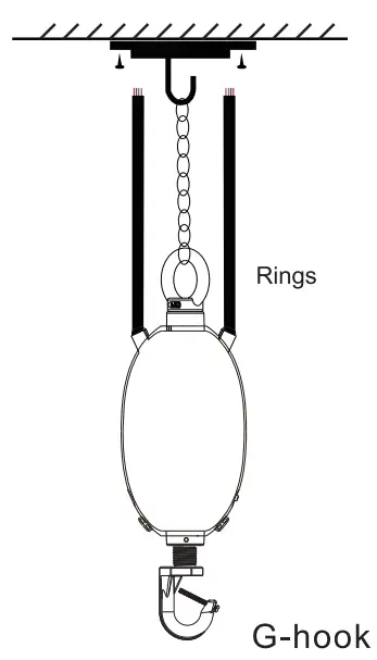
Ring Mounit
Product includes the following components:
| NO. | PICTURE | PARTS | QUANTITY | REMARK |
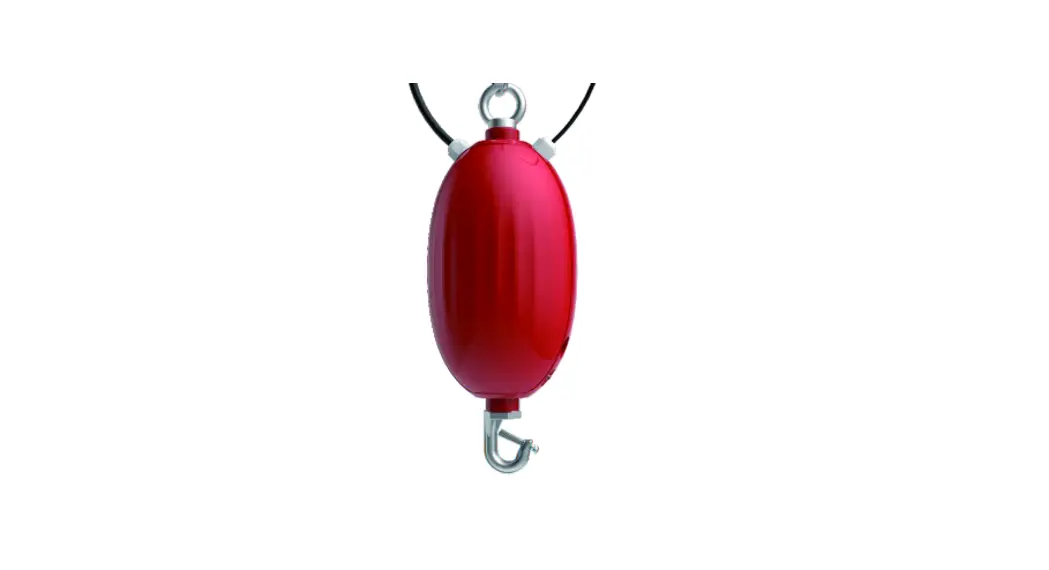
| 1 |  | Rugby LED Emergency Driver | 1 | |
| 2 |  | Ring | 1 | |
| 3 | 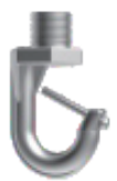 | G-HOOK | 1 | |
| 4 | 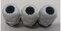 | Waterproof Connectors (For AC Wires) | 3 | Cable Range: 6-12mm |
| 5 | 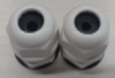 | Waterproof Connectors (For Dimming Wires) | 2 | Cable Range: 5-9mm |
| 6 | 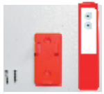 | Remote Controller (Includes 2 Tek screws) | 1 | |
| 7 |  | Philips Head Screws | 2 | |
| 8 | 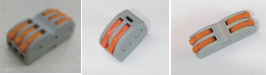 | Wiring Connectors | 5 | Inside Housing |
| 9 | Instruction Sheet | 1 |
See instruction manual,for typical installation and select appropriate mounting method.
Installation Steps![]() CAUTION: Before installing, make certain the AC power is off
CAUTION: Before installing, make certain the AC power is off
Step #1
(A)Disconnect all power sources to the lighting fixture and ensure they are locked out during installation and maintenance.
(B)Select a suitable location on the ceiling for proper mounting of LED emergency driver
Step#2
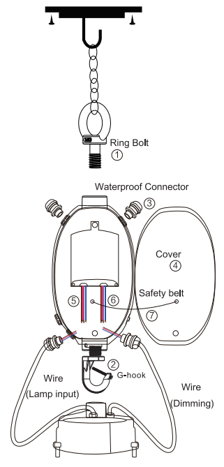
(A) Install the ring bolt to the top thread hole of LED emergency driver and fix it with screw. (B1) Install the G-hook to the Bottom thread hole of LED emergency driver and fix it with screw.
(C) Install the LED emergency driver to UFO highbay fixture with screw. Open the LED emergency cover and remove the plastic covers and install the waterproof connectors.
(D) The suitable cord diameter for waterproof connector.
Step#3
Pull all wires through the waterproof connectors into the Cavity of emergency driver.
(A): Connect the AC output wires ( Brown,Blue and Green) of emergency driver with AC input wires of LED lighting fixture.
(B): Connect the dimming output wires ( Purple and Pink) of emergency driver with the dimming input wires of LED Driver.
(C): Connect AC input wires (Black,White and Red) of emergency driver with AC main power cord .(Preinstalled )
(D): Connect the input dimming wires (Purple,Pink) of emergency driver with dimming wires from dimmer.(Preinstalled )
(E) Close and lock emergency driver and secure shut using screw Make sure all connections are in accordance with manufacture’s installation details.
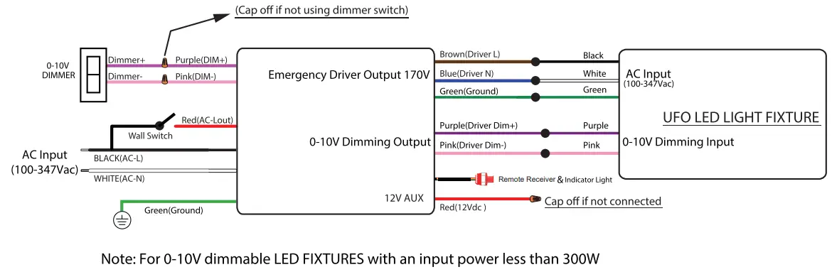
WIRING DIAGRAM
![]() IMPORTANT EM driver output dimming wires must connect to 0-10V dimming wires (DIM+, DIM-) of fixture LED driver. Will NOT operate if not connected.
IMPORTANT EM driver output dimming wires must connect to 0-10V dimming wires (DIM+, DIM-) of fixture LED driver. Will NOT operate if not connected.
Typical wiring diagram
OPERATION
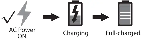
AC Operation: AC power is present.The AC driver operates the LED load as designed.The emergency driver is charging in a standby mode. The charging indicator will be lit, showing that the battery is charging.
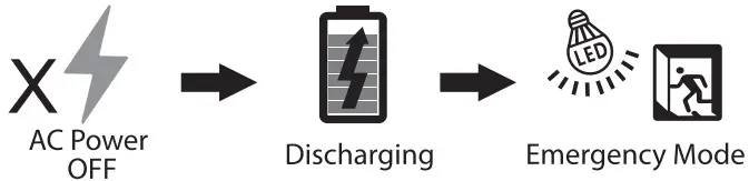
Emergency Operation: When the AC power goes out, the emergency driver detects the AC power outage and automatically switch to emergency mode. When red LED light is OFF, that means driver is discharging. When the AC power is restored, the emergency driver goes back to AC power and starts recharging.
 |  |
| Indicator Light Introduction 1. RED /ON: Charging 2. RED/ OFF: Discharging | 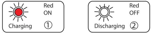 |
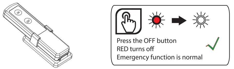
Remote Controller IntroductionON Press the ON button to test emergency function. This light will switch to its emergency ighting mode and the indicator light will turn off. Press the OFF button, the light will revert to normal lighting mode.OFF When main power supply is OFF( emergency mode), press the OFF button to turn off emergency function.
 Note: Remote must be pointed at the indicator light and be within a 45 degree angle to send signal to LED emergency driver. Remote controls requires two AAA batteries to operate. Batteries are not included.
IMPORTANT
DIMMING WIRES MUST BE CONNECTED TO ROUND HIGH BAY LED DRIVER DIMMING WIRES FOR EM TO FUNCTION PROPERLY, IT WILL NOT OPERATE IF NOT CONNECTED.
RECOMMENDATION
EMERGENCY OUTPUT POWER ≥20Wo OUTPUT POWER OF THE ROUND HIGH BAY.


