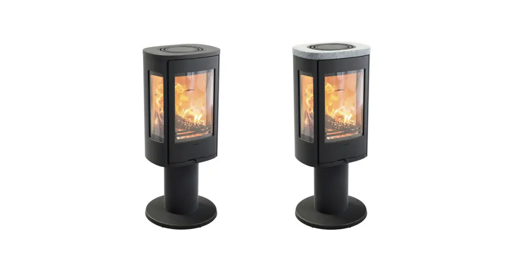
![]() C886 Style
C886 Style
C886G Style
Wood Burning Stove
Instruction Manual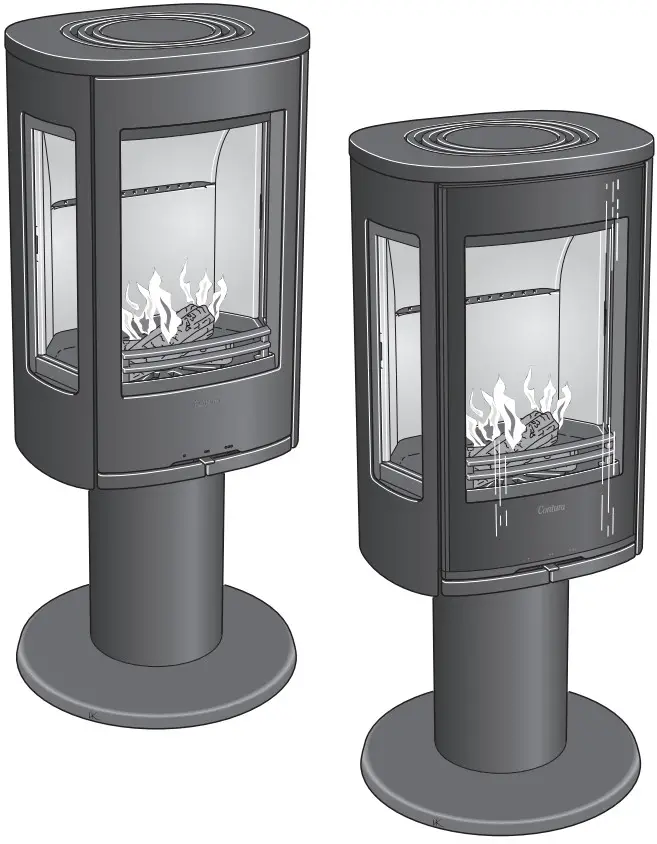
Facts
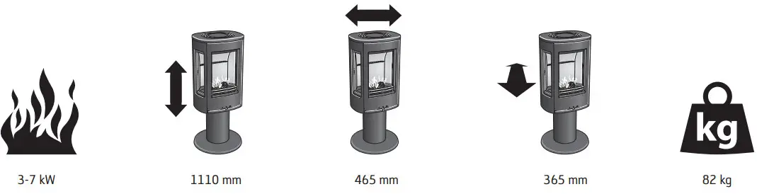
| Nominal effect | 5 kW |
| Efficiency | 81% |
| Flue gas temperature in the connection at nominal output | |
| 309°C | |
| Flue gas mass flow | 4,3 g/s |
Type approved in accordance with:
European standard EN-13240
NS 3059 (Norway)
BImSchV.2 (Germany)
Art. 15a B-VG (Austria)
Clean Air Act. (UK)![]()
The stove becomes very hot
During operation, certain surfaces of the stove become very hot and can cause burn injury if touched. Be aware of the strong heat radiated through the hatch glass. Placing flammable material closer than the safe distance indicated may cause a fire. Pyre lighting can cause quick gas ignition with the risk of damage to property and personal injury.
Installation by an authorized technician
This manual contains instructions about how the stoves must be assembled and installed. To ensure the function and safety of the stove, we recommend that the installation is carried out by an authorized technician. Contact one of our dealers who can recommend suitable technicians.
Building application
These main instructions may give guidance that would contravene national building regulations. Please refer to supplementary instructions or ask your local authority for advice regarding building regulations. Before installing a stove or erecting a chimney it is necessary for you to make a building application permission to your local authority. The owner of the house is personally responsible for ensuring compliance with the mandatory safety requirements and must have the installation approved by a qualified inspector. Your local chimney sweep must also be informed about the installation as this will affect the routines for regular chimney sweeping services.
Structural support
Check that the wood joists are strong enough to bear the weight of the stove and chimney. The stove and chimney can usually be placed on a normal wooden joist in a single occupancy house if the total weight does not exceed 400 kg.
Hearth plate
Due to the risk of falling embers, a flammable floor must be protected by a hearth plate. It must extend 300 mm in front of the stove and 100 mm on each side of the stove, or have a 200 mm extension on each side of the opening. The hearth plate can consist of natural stone, concrete, metal plate, or glass. A glass hearth plate is available as an accessory for these models.
Final inspection of the installation
It is extremely important that the installation is inspected by an authorized chimney sweep before the stove is used. Also, read the ”Lighting Instructions”, before lighting for the
first time.
Connection to chimney
- The stove must be connected to chimneys dimensioned for a minimum flue gas temperature of 400°C.
- The external diameter of the connection sleeve is 150 mm.
- Normal chimney draws under nominal operation should be between 20-25 Pa close to the connector. The draft is affected both by the length and area of the chimney and by how well-sealed it is. The Minimum recommended chimney length is 3.5 m and the suitable cross-section area is 150-200 cm² (140-160 mm in diameter).
- A flue with sharp bends and horizontal routing reduces the draught in the chimney. The maximum horizontal flue is 1 m, on the condition that the vertical flue length is at least 5 m.
- It must be possible to sweep the full length of the flue and the soot hatches must be easily accessible.
- Carefully check that the chimney is sealed and that there is no leakage around soot hatches and flue connections. See page 41.
- The stove meets the requirements for connection to a branched flue pipe.
Supply of combustion air
When a stove is installed in a room, the demand for air supply to the room increases. Air can be provided indirectly via a vent in the outer wall or via a duct from the outside that is connected to the connector underneath the stove. The amount of air needed for combustion is 15 m 3/h.
The connector for the combustion air has an external diameter of 67 mm. When duct routing is further than 1 m the pipe diameter must be increased to 100 mm and a correspondingly larger wall vent must be selected.
In hot areas, the duct should be insulated with 30 mm mineral wool with a moisture-inhibiting outer cover. It is also important to seal around the hole in the wall (or floor) of the lead-in using a sealant.
A 1 m length of condensation insulated ducting for combustion air is available as an accessory. See page 43.
Contura reserves the right to change the dimensions and procedures described in these instructions at any time without special notice. The current edition can be downloaded from www.contura.eu
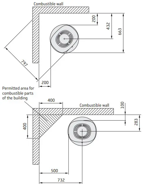
Installation distances
C886 / C886G Style
WHEN INSTALLING TURNTABLE (OPTION) the following installation distances do not apply.
See the separate turntable installation instructions.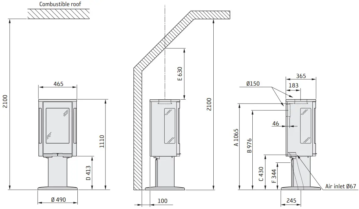 The minimum distance in front of the stove opening to combustible parts of the building or interior decoration must be at least 1,1 m.
The dimension diagrams only show the minimum permitted installation distances for the stove. When connecting to a steel flue, also note the safety distance requirements of the flue. The safety distance between an uninsulated flue and a combustible part of the building should be at least 450 mm.
A = height from floor to chimney connection upwards
B = height from floor to c/c chimney connection rear
C = height from floor to air inlet
D = height from floor to lower edge of the hatch
E = minimum height to the sloped ceiling from the center of the chimney
F = height from floor to knockout in the pedestal
| INSTALLATION AGAINST COMBUSTIBLE WALLS | INSTALLATION AGAINST FIREWALLS |
 | 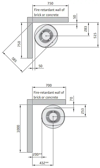 |
** To prevent discoloration of painted non-flammable walls we recommend that the same side distance as to combustible walls is used.
Declaration of performance according to Regulation (EU) 305/2011
No. C886-CPR-191219
| PRODUCT | |
| Type | Wood burning stove |
| Trade name | Contura 886 |
| The intended area of use | Heating of rooms in residential buildings |
| Fuel | Wood |
| MANUFACTURER | |
| Name | NIBE AB / Contura |
| Address | Box 134, Skulptörvägen 10 SE-285 23 Markaryd, Sweden |
| VERIFICATION | |
| According to AVCP | System 3 |
| European standard | EN 13240:2001 / A2:2004 / AC:2007 |
| Test institute | Danish Technological Institute, NB 1235 |
DECLARED PERFORMANCE
| ESSENTIAL CHARACTERISTICS | PERFORMANCE | HARMONISED TECHNICAL SPECIFICATION |
| Fire safety | Pass | EN 13240:2001 / A2:2004 /AC:2007 |
| Fire classification | A1 | |
| Minimum distance to flammable materials | Rear: 100 mm Side: 500 mm Ceiling: 990 mm Front: 1100 mm Floor: 0 mm Corner: 200 mm | |
| Fire hazard due to burning fuel falling out | Pass | |
| Cleanability | Pass | |
| Emissions from combustion | CO: 0,11% | |
| Surface temperatures | Pass | |
| The temperature on the handle | Pass | |
| Mechanical resistance | Pass | |
| The temperature in the space for wood storage | NPD | |
| Nominal output | 5,0 kW | |
| Efficiency | 81,0% | |
| Flue gas temperature at nominal output | 259°C | |
| Flue gas temperature in flue spigot | 314°C |
The undersigned is responsible for the manufacture and conformity with the declared performance. Niklas Gunnarsson, Business area manager NIBE STOVES
Markaryd, January 1, 2022![]()
EU Declaration of Conformity
| Manufacturer | NIBE AB / Contura |
| Address | Box 134, Skulptörvägen 10 285 23 Markaryd, Sweden |
| [email protected] | |
| Website | www.contura.eu |
| Telephone | +46 433 275100 |
THIS DECLARATION OF CONFORMITY IS ISSUED UNDER OUR SOLE RESPONSIBILITY FOR THE FOLLOWING PRODUCT:”
| Trade name | Contura 800 Style-series: 810 (W) / 820T / 856 (T/W) / 870 / 886 / 890 (T) / 896 |
| Identification of product | www.contura.eu |
THE OBJECT OF THE DECLARATION DESCRIBED ABOVE IS IN CONFORMITY WITH
| THE RELEVANT UNION HARMONIZATION LEGISLATION: | THE RELEVANT HARMONIZED STANDARDS: |
| DIR 2009/125/EC | EN 13240:2001/A2:2004/AC:2007 |
| REG (EU) 2015/1185 | CEN/TS 15883:2010 |
| REG (EU) 2015/1186 | |
| REG (EU) 2017/1369 | |
| REG (EU) 305/2011 | |
| TECHNICAL DOCUMENTATION | |
| Indirect heating functionality: | No |
| Direct heat output: | 5,0 kW |
| Energy Efficiency Index (EEI): | 107,5 |
| Test report | 300-ELAB-2412-EN, NB 1235 |
| FUEL | PREFERRED FUEL | OTHER SUITABLE FUEL | η S (%) | EMISSIONS AT NOMINAL HEAT OUTPUT
mg/ Nm3 (13% 0²) | |||||||
| Wood logs with a moisture content of 25% | Yes | No | 71,0 | <40 | <120 | <1500 | <200 | ||||
| Compressed wood with moisture content <12% | No | Yes | 71,0 | <40 | <120 | <1500 | <200 | ||||
| Other woody biomass | No | No | |||||||||
| Non-wood biomass | No | No | |||||||||
| Anthracite and dry steam coal | No | No | |||||||||
| Hard coke | No | No | |||||||||
| Low-temperature coke | No | No | |||||||||
| Bituminous coal | No | No | |||||||||
| Lignite briquettes | No | No | |||||||||
| Peat briquettes | No | No | |||||||||
| Blended fossil fuel briquettes | No | No | |||||||||
| Other fossil fuel | No | No | |||||||||
| Blended biomass and fossil fuel briquettes | No | No | |||||||||
| Another blend of biomass and solid fuel | No | No | |||||||||
CHARACTERISTICS WHEN OPERATING WITH THE PREFERRED FUEL
| ITEM | SYMBOL | VALUE | UNIT | ITEM | SYMBOL | VALUE | UNIT |
| HEAT OUTPUT | USEFUL EFFICIENCY, BASED ON NET CALORIFIC VALUE (NCV ) | ||||||
| Nominal heat output: | Pnom | 5,0 | kW | Useful efficiency at the nominal heat output | η th, nom | 81,0 | % |
| AUXILIARY ELECTRICITY CONSUMPTION | TYPE OF HEAT OUTPUT/ROOM TEMPERATURE CONTROL | ||||||
| At nominal heat output | elmax | – | kW | Single-stage heat output, no room temperature control | Yes | ||
| At minimum heat output | elmin | – | kW | Two or more manual stages, no room temperature control | No | ||
| In standby mode | elSB | – | kW | With mechanic thermostat room temperature control | No | ||
| With electronic room temperature control | No | ||||||
| With electronic room temperature control plus a day timer | No | ||||||
| With electronic room temperature control plus week timer | No | ||||||
OTHER CONTROL OPTIONS | |||||||
| Room temperature control, with presence detection | No | ||||||
| Room temperature control, with open window detection | No | ||||||
| With the distance control option | |||||||
| Specific precautions for assembly, installation, or maintenance. | Fire protection and safety distances to combustible building materials must be observed under all circumstances. A sufficient supply of combustion air must always be guaranteed. Air suction systems can interfere with the combustion air supply. | ||||||
The undersigned is responsible for the manufacture and conformity with the declared performance.Niklas Gunnarsson, Business area manager NIBE STOVES
Markaryd, January 1, 2022
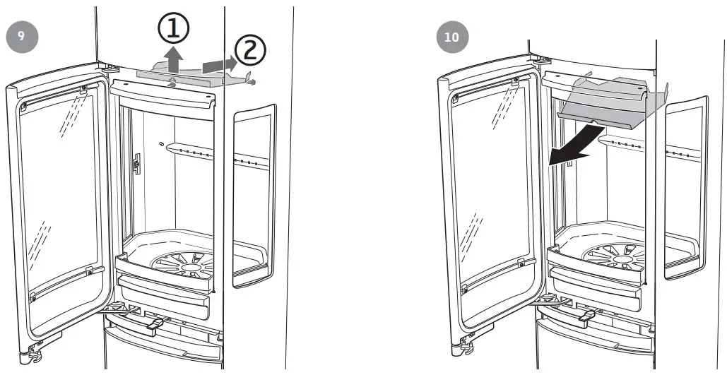
Prior to installation
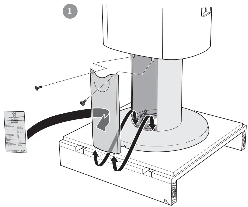 | 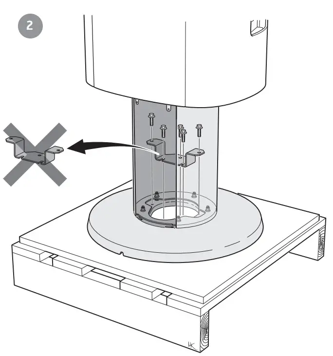 |
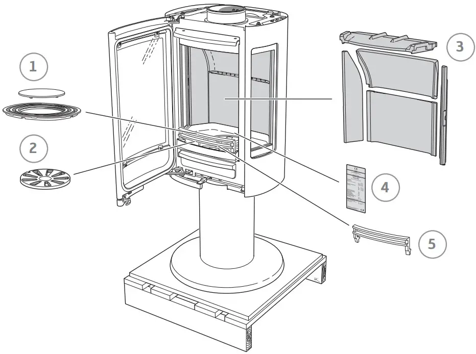
If the insert needs to be put down to be moved, loose components should be removed. Removal of the hearth cladding is described at the end of these installation instructions.
- Grille
- Grate disc
- Hearth cladding (Vermiculite)
- Type plate
- Fire bars
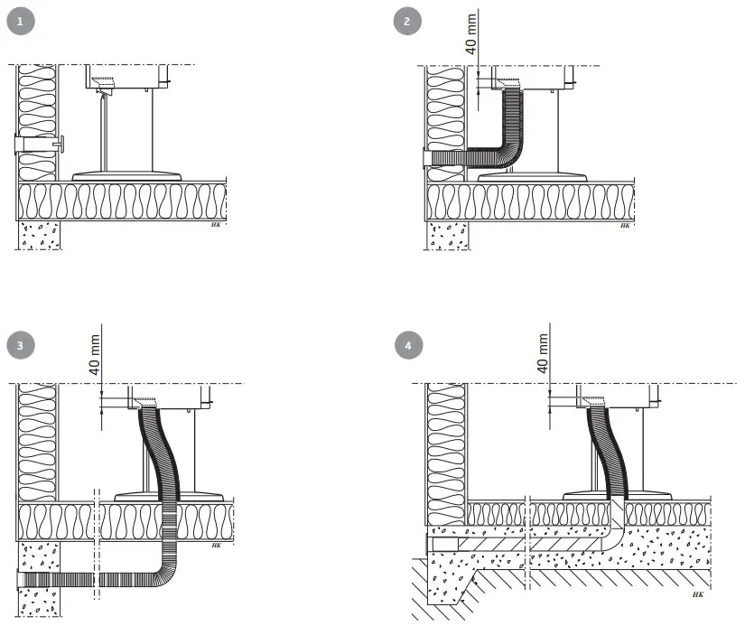
 Rear connection to the chimney
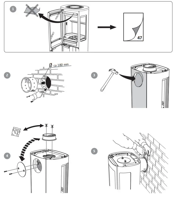 Top connection to the chimney
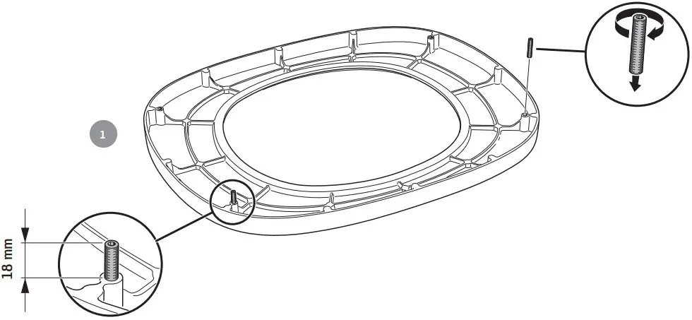
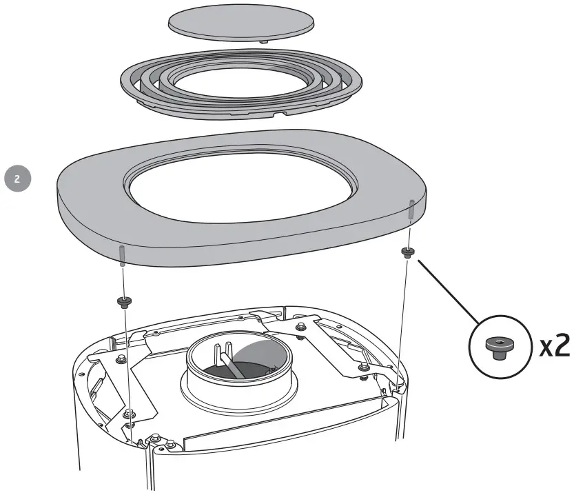
The hot air grille must be installed before the chimney top connection.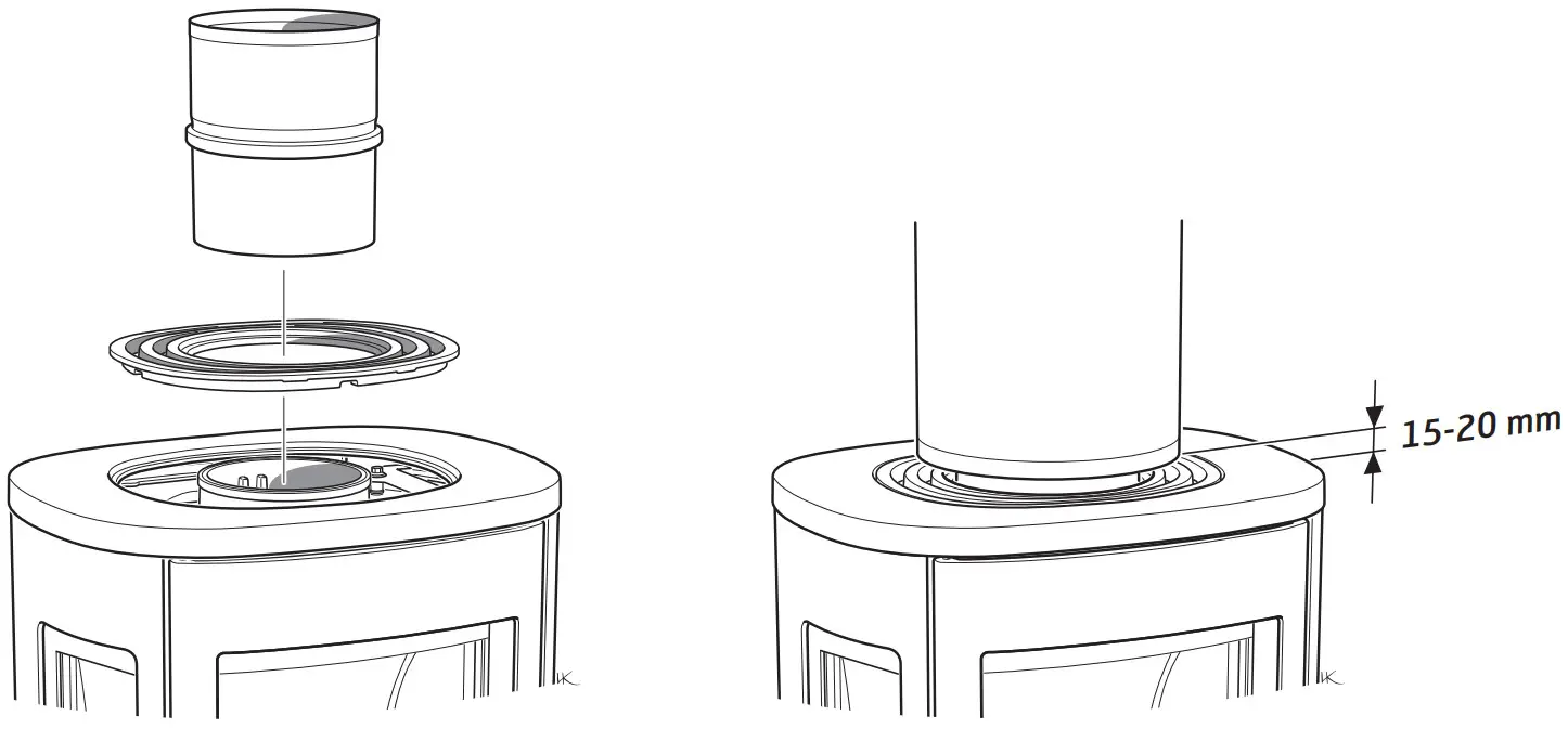 Supply
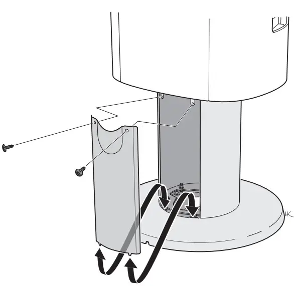
 |  |
Door in the open position, for cleaning/service
The door can be secured in the open position using the locking lever on the left side of the stove.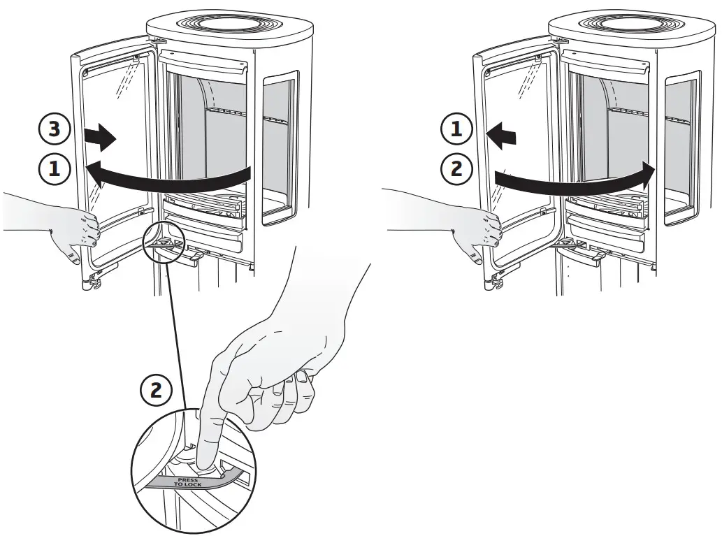 How to remove the hearth surround (Vermiculite)
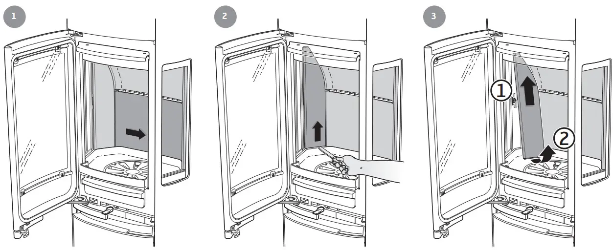 |
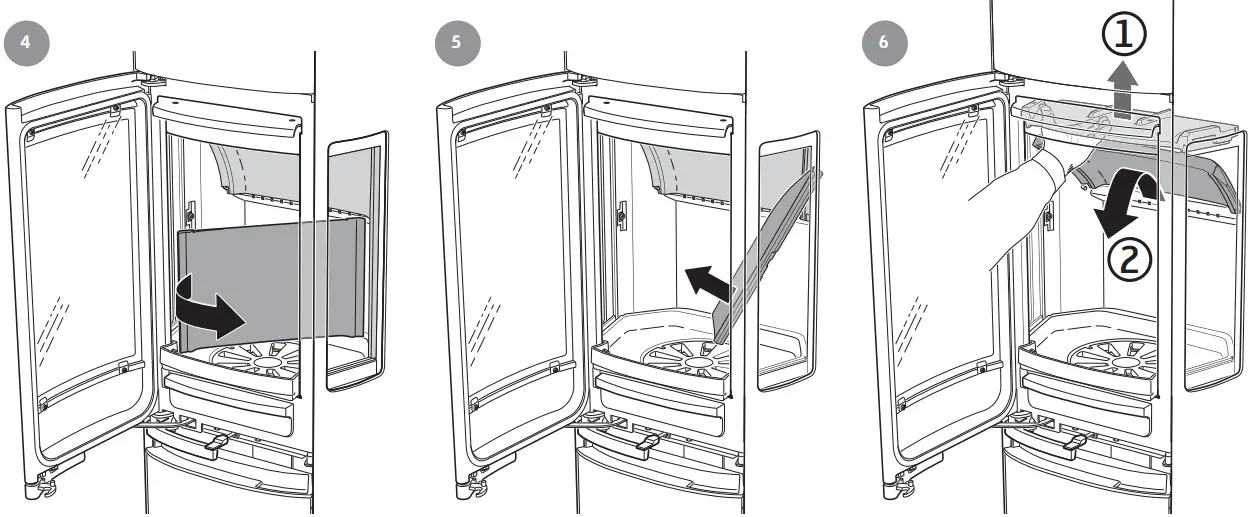 |
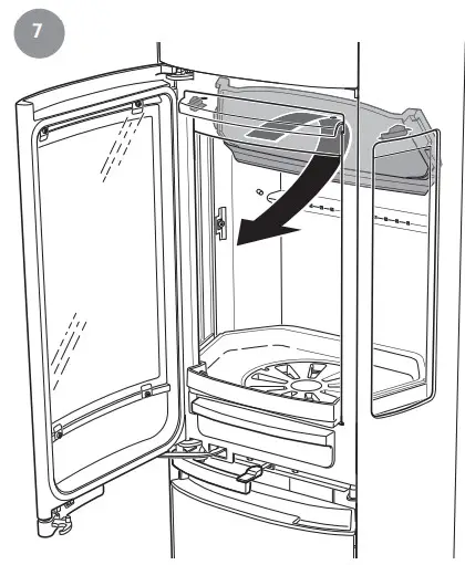 |
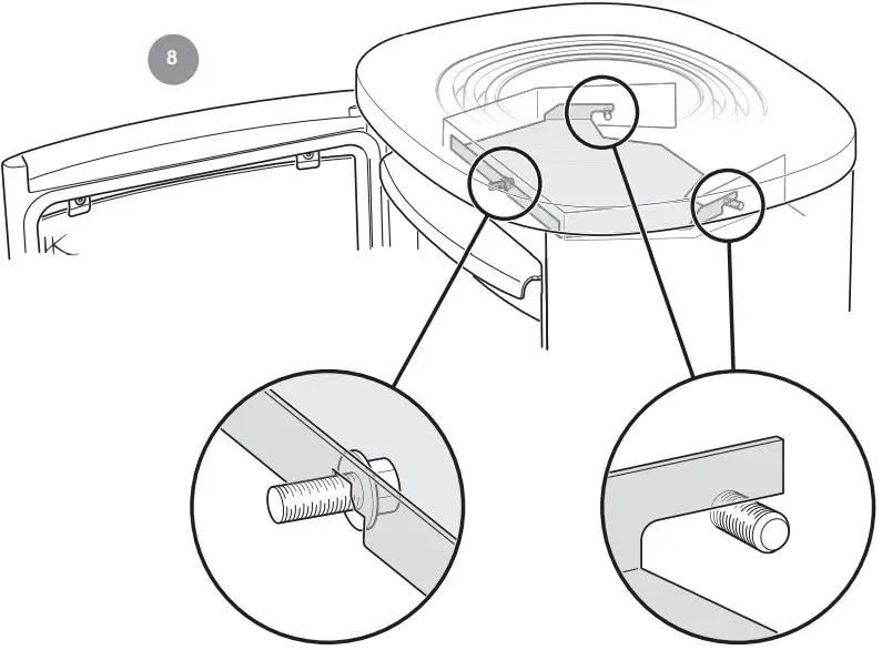 |
 |
![]() NIBE AB
NIBE AB
· Box 134
· 285 23 Markaryd
· Sweden
Contura.eu
811391 IAV SE-EX C886 Style-7


