![]() Wiring Instructions
Wiring Instructions
Twin Fan Controller
Controller Inputs
| Input Purpose | Input Type | Signal Type | Designation | Operation Logic | Comments |
| Power Supply In | Analogue | 220/240V | 240V Supply In | Mains Supply should have own insulator | |
| Power Supply Out | Analogue | 220/240V | 240V Supply Out | AUX Mains Supply Output (1A) | |
| Power Supply To Fan 1 | Analogue | 220/240V | 240V Supply Out | Mains Supply 4A Max | |
| Power Supply To Fan 2 | Analogue | 220/240V | 240V Supply Out | Mains Supply 4A Max | |
| Medium Speed Boost Input | Analogue | 220/240V | 240V Supply In | 240V Switched input increases speed to medium | |
| High Boost Speed | Analogue | Dry Contact | High Boost | No | Contact Closed = “High Boost” Fan Speed |
| Medium Boost Speed | Analogue | Dry Contact | Med Boost | No | Contact Closed = “Med Boost” Fan Speed |
| 0-10y Speed Control | Analogue | OV-10V | 0>10V+ | External Speed Control |
Controller Outputs
| Output Purpose | Output Type | Signal Type | Designation | Note |
| Fault Output Relay | Analogue | Dry Contact | Fault Out | Volt Free Contact – Closed = No Fault Open = Fault |
| 10V DC Output Speed Control | Analogue | 10V | +10V | 10V Out DC Supply for exernal Pot (10K) |
| 24V DC Output | Analogue | 24V Out | 24V Out | 24V Output (80MA) For External Sensor (Unregulated) |
| Fan1 Operation + Speed Control | Analogue | OV-10V | Fan 1 | Speed Control and RPM Signal Monitoring |
| Fang Operation + Speed Control | Analogue | OV-10V | Fan 2 | Speed Control and RPM Signal Monitoring |
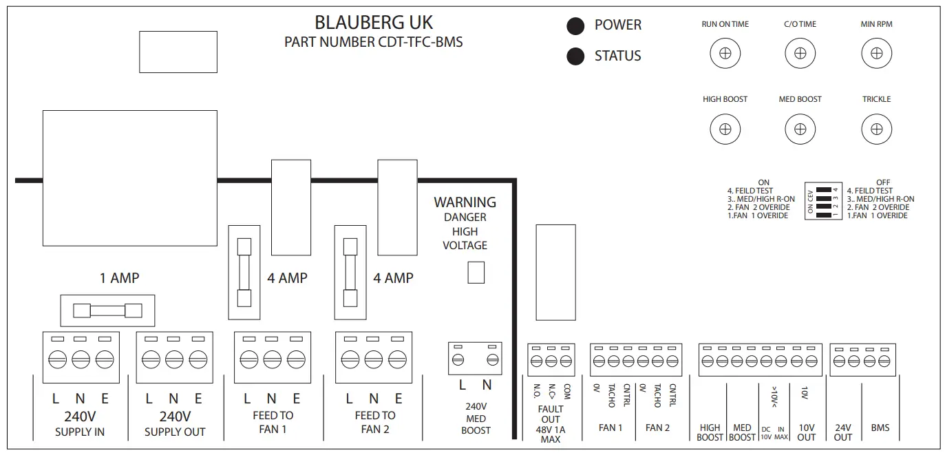
Controller power supply and connections
INPUT / OUTPUT / OPTIONS / FUNCTION SETTINGS.
Mains Supply in.
- 3 way mains terminal block (unit will need a fused supply)
Mains supply out (Auxiliary)
- Mains supply out, via a 1 Amp fuse.
Fan 1
- Mains Feed (L N & E)
- Speed control signal output (0 to 100% PWM)
- Tacho monitoring input (RPM signal)
Fan 2
• Mains Feed (L N & E)
• Speed control signal output (0 to 100% PWM)
• Tacho monitoring input (RPM signal)
PCB control setting pots
| • Trickle fan speed • Medium Boost speed • High Boost speed • Min RPM fan speed • Fan C/O (changeover) Time • Run On Time (for both Boost speeds) | (0 to 100% PWM) : : (50 to 250 RPM) (1 to 12 hours) (0 to 15 mins) |
Low Voltage Switch Inputs
- VFC for BMS Enable (volt free contacts Closed = Run, Open =stop)
- VFCa Medium Boost Speed (volt free contacts Closed = Med, Open = Trickle )
- VFCb High Boost Speed (contact Closed = High speed, Open = Trickle or Medium)
240V AC Medium Boost input
- Isolated 240V AC input will select Medium Boost speed (works in parallel with VFCa switch input)
0 > 10V IN
- External speed control (0 to 10V DC)
0V = Trickle Speed to 10V = maximum fan speed.
NOTE Range maximum speed could be limited to High Boost Speed setting?
Outputs
- Fault Output relay (voltage free contacts, Closed = no fault, Open = fault) Fail safe
- 10V Out DC supply for external user speed control pot (10K pot).
- Nominal 24V DC for powering external sensor unit (maximum 80mA)
LED 1 – Power Indicator [Yellow]
LED 2 – Status [Green]
| • Off • Steady On • Flashing (Slow) • Flashing (Fast) | = no power = all OK = BMS Enable off = fan fault (Fan 1 or Fan 2 or both) |
PCB Mode DIP switches
- Fan 1 Override (On runs Fan 1 continually and disables Fan 2*).
- Fan 2 Override (On runs Fan 2 continually and disables Fan 1*).
- Selects whether Run On time applies to Medium Boost only or to Medium Boost and High Boost inputs.
- Field Test Mode (see section 3.1.2 below).
*If both Fan 1 Override and Fan 2 Override are on at the same time, both fans run continually (duplex mode). See NOTE at end of section 3.1.
Operation Logic
Start up checks
On initial power up the fault output relay will be energized in the normal “No Fault” condition.
Fan No 2 will be run for 30 seconds, to allow the controller to monitor the correct running of the fan.
If no fan fault is detected the controller will switch off fan No 2 and bring on fan No 1.
If fan No 2 is found to be faulty the fault relay output will go into fault condition, and the status LED will fast flash and fan No 1 will be turned on.
OR
If fan No 1 is found to be faulty the fault relay output will go into fault condition, and the status LED will fast flash and fan No2 will be turned on.
NOTE
If the installation only has one fan, then set Fan 1 mode switch to Override and connect the fan to the Fan 1 terminals. Fan 2 Power Up test will not occur. If both fans are to run continually then put Fan 1 and Fan 2 mode switches to Override. Both fans will now be monitored for correct operation. Fan 1 and Fan 2 Power Up tests will not occur.
3.1.1 Fan fault monitoring
Any fan that should be running will be monitored, and if its RPM falls below the Minimum RPM speed setting the Fault Output relay will switch to Fault. NOTE a fault output will also be generated for lack of mains power.
To ensure that false alarm outputs are not produced the controller will monitor the fan/s for 30 seconds of continuous fault condition before producing a fault output.
If a fan is found to be faulty the status LED will fast flash and the fault relay remains in the fault condition until such time as the system is reset. Manual fault reset is required.
3.1.2 Field Test mode
Field Test mode reduces the Changeover Time range to 1 to 12 minutes and the Run On Time range to 0 to 15 seconds, for quicker testing during commissioning.
3.2 Fan Speed setting
The Low, Medium & High fan speeds allow for full commissioning.
The speed setting pots have a basic scaling of 0, 2.5, 5, 7.5 & 10, corresponding to 0 to 100% PWM (0 to 10V).
Changeover mode
After the initial power up checks fan No 1 will run for the pre-set time. At the end of the run period Fan No 2 will turn on and Fan No 1 will turn off. If no fan faults are detected this sequence repeats.
If a fan fault is detected the Fault Output relay will switch to the fault condition and the status LED will flash rapidly.
The running fan will turn off and the standby fan will turn on until the controller is reset.
Boost inputs
If switch inputs VFCa (or the 240V Medium Boost input) or VFCb operate, the fan/s will run at the selected Boost speed. Whilst any boost signal is present the 0 > 10V input will be ignored, and the fan/s will run at the boost speed.
If high boost and medium boost inputs are active – high boost fan speed is used.
There is two “Boost” modes:
MEDIUM BOOST SPEED
Volt free contact input VFCa. When the contacts close the Medium Boost speed will be selected. Isolated 240V AC input. When applied the Medium Boost speed will be selected.
RUN ON TIME
The Fan/s will continue to run for the period set by the “Run ON Time” control.
HIGH BOOST SPEED
Volts free contact input VFCb. When the contacts close the High Boost speed will be selected. NOTE The High Boost can also trigger the Run In Timer if selected by the appropriate mode switch
PRIORITY OF BOOST SIGNALS
Medium Boost will override the Trickle fan speed setting and the 0 > 10V input.
High Boost will override Medium Boost, the Trickle fan speed and the 0 >10V input.
A boost signal will take control of the fan speed whether the boost speed is higher or lower than the fan speed it is overriding.
BMS Enable input
The VFC BMS Enable input must be connected or linked for the controller to operate. This is for remote control by a Building Management System or other control system.
If the Enable input is opened whilst running then the fan/s will be turned off and the Fault Output relay will switch to the fault condition.
![]()


