![]()
UL,ULC Listed; FM Approved*
Datasheet
TrueAlert Addressable Notification Appliances
Ceiling Mount Addressable Speaker Visible (S/V) Notification Appliances
Introduction
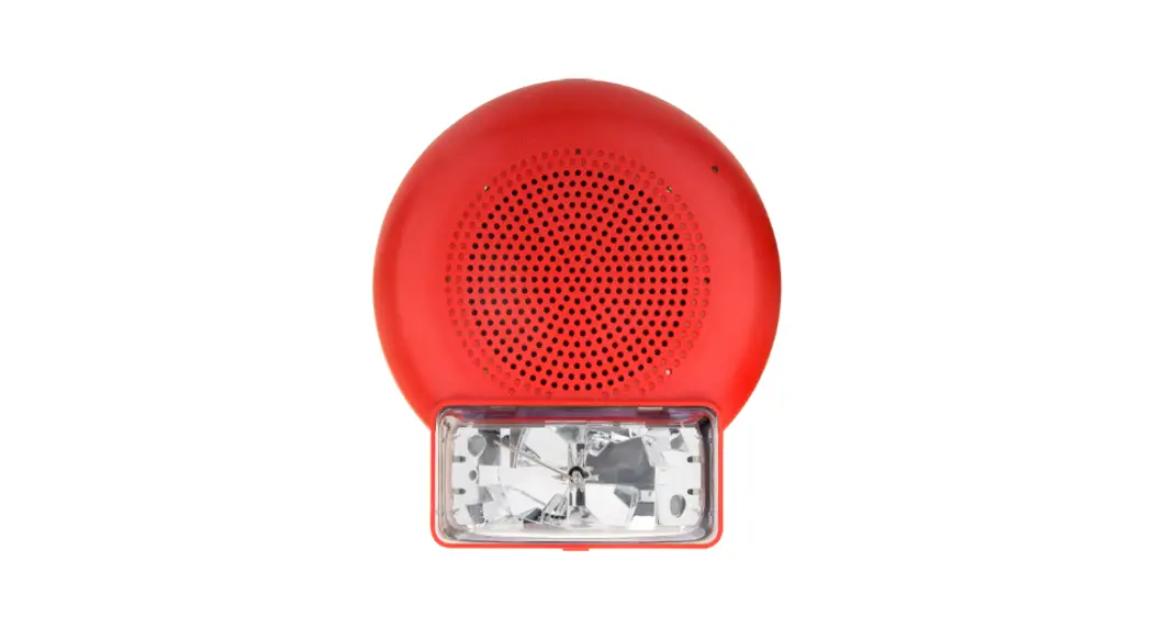
Ceiling mount addressable speaker visible (S/V) notification appliances
Use the Simplex fire alarm control unit (FACU) IDNAC signaling line circuit (SLC) to individually power, address, and control ceiling mount addressable S/V notification appliances. A separate compatible Simplex FACU audio NAC supplies audio. Electronic monitoring of wiring supervision means you can T-tap audio and IDNAC wiring for Class B wiring, reducing wiring costs and wiring distances.
Install ceiling mount addressable S/V notification appliances on a standard 4 in. (101.6 mm) square 2 1/8 in. (53.97 mm) deep electrical box, provided by others, for flush installations. Install on a surface or weatherproof backbox, see Table 8 for surface or weatherproof (WP) installations.
Appliances are available in 400 Hz to 4000 Hz and 200 Hz to 10000 Hz high fidelity models. Select the appliance and cover it separately to simplify the ordering and installation process. Model numbers ending in –BA are assembled in the USA. For more information, refer to datasheet S49SWC-0001.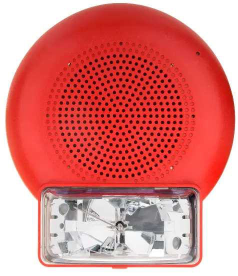
Figure 1: Ceiling mount addressable S/V notification appliance
Ceiling mount addressable speaker product selection
Table 1: Ceiling mount addressable speaker S/V appliances
| Model | Description | Installation instructions |
| 49SV-APPLC 49SV-APPLC-BA | S/V appliance only. If required, select a cover and surface or WP box separately. | 579-1203 |
Table 2: High fidelity appliances
| Model | Description | Installation instructions |
| 49HFV-APPLC 49HFV-APPLC-BA | High fidelity S/V appliance only. If required, select a cover and surface or WP box separately. | 579-1203 |
Table 3: High candela appliances
| Model | Description | Installation instructions |
| 49SVH-APPLC-O 49SVH-APPLC-CO (Canada only) | S/V Appliance Only. Select a cover and surface or WP box separately | 579-1241 |
Table 5: S/V covers, required when ordering APPLC models
| SKU | Color | Wording |
| 49SVC-CRALT-O | Red | ALERT |
| 49SVC-CWALT-O | White | |
| 49SVC-CRBA-O | Red | FIRE |
| 49SVC-CWBA-O | White | |
| 49SVC-CRBC-O | Red | FIRE ALARM |
| 49SVC-CWBC-O | White | |
| 49SVC-CRBF-O | Red | FEU/FIRE |
| 49SVC-CWBF-O | White | |
| 49SVC-CRFEU-O | Red | FEU |
| 49SVC-CWFEU-O | White | |
| 49SVC-CRFIRE-O | Red | FIRE |
| 49SVC-CWFIRE-O | White | |
| 49SVC-CRS-O | Red | Simplex logo only |
| 49SVC-CWS-O | White |
Table 5: S/V covers, required when ordering APPLC models
| Model | Color | Wording |
| 49SVC-CRALT | Red | ALERT |
| 49SVC-CWALT | White | |
| 49SVC-CRBA | Red | FIRE |
| 49SVC-CWBA | White | |
| 49SVC-CRBC | Red | FIRE ALARM |
| 49SVC-CWBC | White | |
| 49SVC-CRBF | Red | FIRE |
| 49SVC-CWBF | White | |
| 49SVC-CRFEU | Red | FEU |
| 49SVC-CWFEU | White | |
| 49SVC-CRFBL | Red | FOGO |
| 49SVC-CRFIRE | Red | FIRE |
| 49SVC-CWFIRE | White | |
| 49SVC-CRS | Red | Simplex logo only |
| 49SVC-CWS | White | |
| 49SVC-CK | Black | No logo or lettering |
* Additional listings may be applicable; contact your local Simplex product supplier for the latest status. Listings and approvals under Simplex Time Recorder Co.
Weatherproof product selection
Table 6: Weatherproof ceiling mount addressable S/V appliances
| Model | Description | Installation instructions |
| 49SVH-APPLC-O 49SVH-APPLC-CO (Canada only) | S/V Appliance Only. Select a cover and surface or WP box separately | 579-1241 |
Table 7: S/V covers, required when ordering APPLC-O models
| SKU | Color | Wording |
| 49SVC-CRALT-O | Red | ALERT |
| 49SVC-CWALT-O | White | |
| 49SVC-CRBA-O | Red | FIRE |
| 49SVC-CWBA-O | White | |
| 49SVC-CRBC-O | Red | FIRE ALARM |
| 49SVC-CWBC-O | White | |
| 49SVC-CRBF-O | Red | FIRE |
| 49SVC-CWBF-O | White | |
| 49SVC-CRFEU-O | Red | FEU |
| 49SVC-CWFEU-O | White | |
| 49SVC-CRFIRE-O | Red | FIRE |
| 49SVC-CWFIRE-O | White | |
| 49SVC-CRS-O | Red | Simplex logo only |
| 49SVC-CWS-O | White |
Table 8: Surface or WP back boxes
| SKU | Color | Description | Installation instructions |
| 49WPBB-SVCR | Red | Surface or WP back box in red | 579-1240 |
| 49WPBB-SVCW | White | Surface or WP back box in white |
Table 9: Wire guards and wire guard back boxes
| SKU | Description |
| 49WGBB-SVCR-O | Wire guard back box, ceiling, red, WP |
| 49WG-SVWCR | Wire guard, ceiling, red |
Ceiling mount S/V specifications
Table 10: Non-weatherproof appliance general specifications
| Specification | Rating |
| Dimensions | 8 1/8 in. H x 7 1/8 in. W x 3in. D (206 mm x 180 mm x 76 mm) |
| Environmental | 32°F to 120°F (0°C to 49°C); 10% to 93%, non-condensing at 104°F (40°C) |
| Connections | Terminal blocks for 18 AWG to 12 AWG (0.82 mm2 to 3.31 mm2); two wires for each terminal for in/out wiring. Use unshielded twisted pair (UTP) for IDNAC and audio wiring. |
Table 11: Weatherproof appliance general specifications
| Specification | Rating |
| Dimensions | 8 1/8 in. H x 7 1/8 in. W x 3in. D (206 mm x 180 mm x 76 mm) |
|
Environmental | UL/ULC temperature rating, W110 CD/W135 CD/W185 CD: -40°F to 150.8°F (-40°C to 66°C) UL/ULC temperature rating for indoor and uncontrolled wet Public Mode – 110 CD: 32°F to 120°F (0°C to 49°C) |
| FM temperature rating: -40°F to 120°F (-40°C to 49°C) | |
| UL/ULC humidity range: 95 %, non-condensing at 140°F (60°C) | |
| Connections | Terminal blocks for 18 AWG to 12 AWG (0.82 mm2 to 3.31 mm2); two wires for each terminal for in/out wiring. Use unshielded twisted pair (UTP) for IDNAC and audio wiring. |
Table 12: Speaker audio specifications
| Specification | Rating | |
| Input voltage | 25 Vrms or 70.7 Vrms | |
| Power taps | 1/4 W, 1/2 W, 1 W, and 2 W | |
| Frequency response | 400 Hz to 4000 Hz (S/V, S/VH), 200 Hz to 10000 Hz (H/F, HF/VH) | General Signaling = 125 Hz to 12 kHz |
Table 13: Speaker output ratings
| Wattage tap | 1/4 W | 1/2 W | 1 W | 2 W | ||||
| Model | S/V | H/F | S/V | H/F | S/V | H/F | S/V | H/F |
| Reverberant chamber test, in accordance with UL 1480 (dBA) | 79 | 76 | 83 | 80 | 86* | 84 | 89* | 87* |
| Anechoic chamber test, in accordance with ULC-S541 (dBA)* | 79 | 78 | 83 | 82 | 86* | 85* | 89* | 88* |
| * Select taps as indicated to satisfy the ULC fire alarm applications requirement of 85 dBA minimum | ||||||||
| Polar dispersion reference in accordance with ULC-S541 Anechoic Chamber Testing | Attenuation | Angle | Attenuation | Angle | ||||
| -3 dB | 70° | -6 dB | 80° | |||||
Table 14: Percentage of rated light
| Angle | On-axis | Vertical, below axis | Horizontal, left/right of axis | ||
| 0° | 45° | 90° | 45° | 90° | |
| UL required output | 100% | 45% | 25% | 45% | 25% |
| Typical output | 327% | 134% | 83% | 129% | 47% |
Table 15: IDNAC SLC specifications
| Specification | Rating |
| Typical operating voltage range | 23 VDC to 30 VDC, Special Application |
| Appliance voltage design reference | 23 VDC (with 6 VDC drop) |
| Supervisory requirements | 1 unit load (= 0.8 mA control unit current) |
| Flash rate and synchronized SLC loading | 1 Hz; with up to 63 synchronized strobes maximum for each powered circuit, max 127 S/V appliances for each IDNAC channel |
| IDC SLC loading | Maximum of 127 addresses for each SLC, 139 unit loads. See device and compatible fire control unit installation instructions for circuit current load limits. |
| IDC SLC wiring specifications refer to the control unit installation instructions for more information | UTP, unshielded twisted pair recommended |
| Maximum wire length allowed with T-taps for Class B wiring for each SLC = 10,000 ft (3048 m) | |
| Maximum wire length to any appliance = 4000 ft (1219 m). This can be doubled to 8000 ft (2438 m) by using a 4009 IDNAC Repeater. |
Table 16: Current consumption**
| Candela setting | 15 cd | 30 cd | 75 cd | 110 cd | 135 cd | 185 cd |
| 49SV and 49HFV models | 59 mA | 82 mA | 145 mA | 193 mA | N/A | N/A |
| 49SVH and 49HFVH models | N/A | N/A | N/A | 259 mA | 281 mA | 325 mA |
| Weatherproof SV appliances | N/A | N/A | N/A | Inside 110CD = 305 mA Outside 110CD = 308 mA | 335 mA | 398 mA |
| ** Measured at 23 VDC on IDNAC Addressable SLC | ||||||
| Speakers are for connection to compatible fire alarm audio circuits. Anechoic speaker output ratings are typically more representative of actual installed sound output. | ||||||
Table 17: Equipment compatibility references
| Compatible equipment | Data sheet reference |
| 4100ES with EPS+ or EPS Power Supply | S4100-0100 |
| 4009 IDNAC Repeater | S4009-0004 |
| 4100ES Flex 35 and 50 Watt Amplifiers | S4100-0034 |
| 4100ES 100 Watt Amplifiers | |
| 4100ES Constant Supervision and Signal Cards |
Ceiling mount S/V installation reference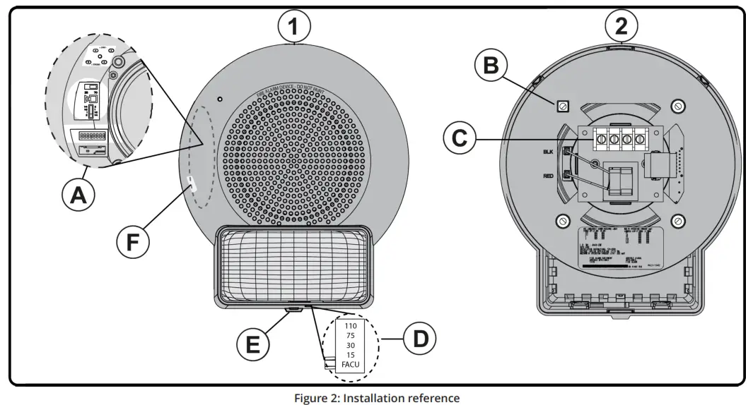
| Callout | Description | Callout | Description |
| 1 | Appliance with cover, front | 2 | Appliance, rear |
| A | Appliance test points, audio circuit power taps, and address dip switch Set audio circuit power taps and device address before fixing cover in place. | B | Mount to 4 in. x 4 in. x 2 1/8 in. electrical box using 8-32 screws. Ceiling mount only. |
| C | Wiring terminals for speaker and strobe connections. These terminals accept two #12-18 AWG wires. | D | Candela flag setting Set flag to FACU to control candela rating from a FACU providing IDNAC notification. To set candela manually, set the flag to the desired candela rating. |
| E | Use slotted screwdriver here to remove cover. | F | Magnet test location indicated by area that is not textured. |
© 2022 Johnson Controls. All rights reserved. All specifications and other information is shown were current as of document revision and are subject to change without notice. Additional listings may be applicable, contact your local Simplex® product supplier for the latest status. Listings and approvals under Simplex Time Recorder Co. Simplex and the product names listed in this material are marks or registered marks. Unauthorized use is strictly prohibited. NFPA 72 and National Fire Alarm Code have registered
trademarks of the National Fire Protection Association (NFPA). S49SVC-0001 Rev. 11 1/2022


