GARMIN GNX 20-21 Wired Sail Pack 52mm Instruction Manual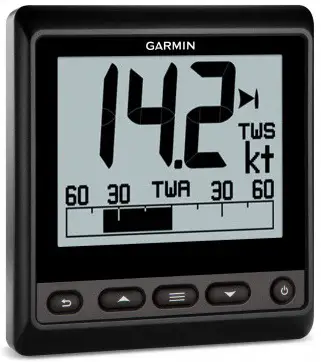
Introduction
To obtain the best possible performance, install this marine instrument according to these instructions. If you experience difficulty during the installation, contact Garmin® Support, or seek the advice of a professional installer.
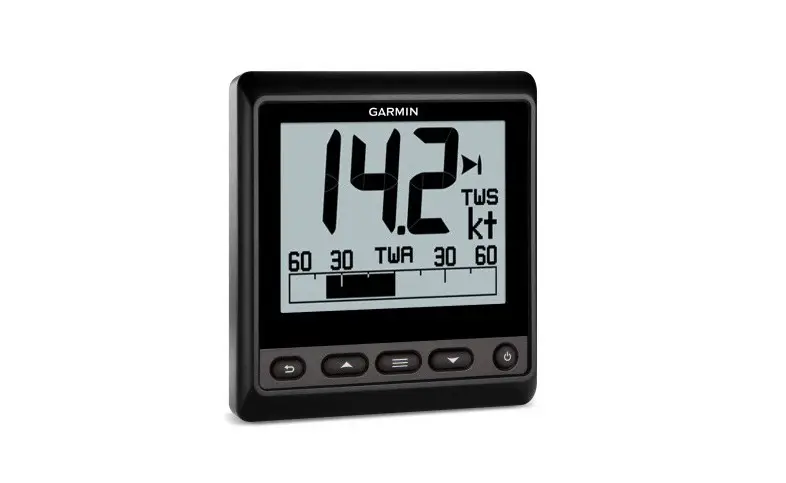
This instrument communicates with NMEA 2000® sensors and devices, and shows information such as speed, heading, and water depth when connected to the appropriate sensors. The instrument can also communicate with a NMEA® 0183 device using an optional data cable.
Important Safety Information
![]() WARNING
WARNING
See the Important Safety and Product Information guide in the product box for product warnings and other important information.
![]() CAUTION
CAUTION
To avoid possible personal injury, always wear safety goggles, ear protection, and a dust mask when drilling, cutting, or sanding.
NOTICE
When drilling or cutting, always check what is on the opposite side of the surface to avoid damaging the vessel.
Mounting Considerations
NOTICE
This device should be mounted in a location that is not exposed to extreme temperatures or conditions. The temperature range for this device is listed in the product specifications. Extended exposure to temperatures exceeding the specified temperature range, in storage or operating conditions, may cause device failure.
Extreme-temperature-induced damage and related consequences are not covered by the warranty.
The mounting surface must be flat to avoid damaging the device when it is mounted.
When selecting a mounting location, observe these considerations.
- The mounting location should be at or below eye level to provide optimal viewing as you operate your vessel.
- The mounting location should be at less than a 45° viewing angle for the GNX 20 Marine Instrument with Standard LCD and less than a 50° viewing angle for the GNX 21 Marine Instrument with Inverted LCD. Screen color inversion occurs when the viewing angle is greater than 30° in the 9 o’clock direction on the GNX 20 and when the viewing angle is greater than 60° in the 1 o’clock direction on the GNX 21.
- The mounting surface must be strong enough to support the weight of the device and protect it from excessive vibration or shock.
- To avoid interference with a magnetic compass, the device should not be installed closer to a compass than the compass-safe distance value listed in the product specifications.
- The area behind the mounting surface must allow room for the routing and connection of the cables.
Mounting the Device
NOTICE
If you are mounting the device in fiberglass, when drilling the pilot holes, use a countersink bit to drill a clearance counterbore through only the top gel-coat layer. This will help to avoid cracking in the gel-coat layer when the screws are tightened.
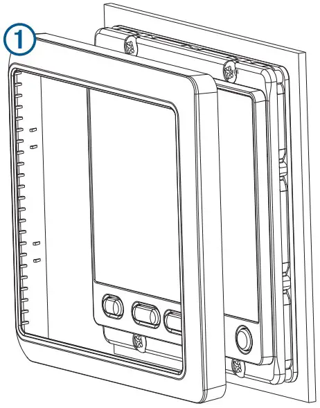
The included template and hardware can be used to flush mount the device in your dashboard.
- Trim the flush-mount template and ensure it fits in the location where you plan to mount the marine instrument.
The flush-mount template is included in the product box. - Remove the liner from the adhesive on the back of the template and adhere it to the location where you plan to mount the marine instrument.
- If you plan to cut the hole using a rotary tool instead of a 90 mm (3.5 in.) hole saw, use a 10 mm (3 /8 in.) drill bit to drill a pilot hole to begin cutting the mounting surface.
- Using the 90 mm (3.5 in.) hole saw or rotary tool, cut the mounting surface along the inside of the dashed line indicated on the flush-mount template.
- If necessary, use a file and sandpaper to refine the size of the hole.
- Place the marine instrument into the cutout to confirm that the mounting holes on the template are in the correct locations.
- If the mounting holes are not correct, mark the correct locations of the mounting holes.
- Remove the marine instrument from the cutout.
- Drill the 2.8 mm (7 /64 in.) pilot holes.
If you are mounting the marine instrument in fiberglass, use a countersink bit as advised in the notice. - Remove the remainder of the template.
- Place the included gasket on the back of the device and apply marine sealant around the gasket to prevent leakage behind the dashboard.
- If you will not have access to the back of the device after you mount it, connect all necessary cables to the device before placing it into the cutout.
NOTE: To prevent corrosion of the metal contacts, cover unused connectors with the attached weather
caps. - Place the marine instrument into the cutout.
- Securely fasten the marine instrument to the mounting surface using the supplied screws.
If you are mounting the marine instrument in fiberglass, use a anti-galling lubricant as advised in the notice. - Snap the bezel into place.

Connection Considerations
The marine instrument connects to power and to data sources through a NMEA 2000 network.
Although the instrument cannot directly receive NMEA 0183 data, it can display NMEA 0183 data from sources
connected to a GNX 20 or GNX 21 device (sold separately) on the same NMEA 2000 network.
The instrument can also receive data from Nexus® instruments and sensors using a GND™ 10 device (sold separately).
NMEA 2000 Connection Considerations
NOTICE
If you are connecting to an existing NMEA 2000 network, identify the NMEA 2000 power cable. Only one NMEA 2000 power cable is required for the NMEA 2000 network to operate properly.
A NMEA 2000 Power Isolator (010-11580-00) should be used in installations where the existing NMEA 2000 network manufacturer is unknown.
If you are installing a NMEA 2000 power cable, you must connect it to the boat ignition switch or through another in-line switch. NMEA 2000 devices will drain your battery if the NMEA 2000 power cable is connected to the battery directly.
The marine instrument connects to a NMEA 2000 network on your boat. The NMEA 2000 network provides power to the marine instrument and data from NMEA 2000 devices such as a wind sensor. The included NMEA 2000 cables and connectors allow you to either connect the device to your existing NMEA 2000 network or create a basic NMEA 2000 network if needed.
If you are unfamiliar with NMEA 2000, you should read the “NMEA 2000 Network Fundamentals” chapter of the
Technical Reference for NMEA 2000 Products. To download the reference, go to garmin.com/manuals/nmea_2000.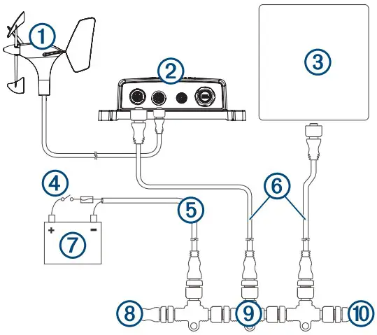
1 | Wind transducer |
2 | GND 10 black box bridge |
3 | Marine instrument |
4 | Ignition or in-line switch |
5 | NMEA 2000 power cable |
6 | NMEA 2000 drop cable |
7 | Power source |
8 | NMEA 2000 terminator or backbone cable |
| 9 | NMEA 2000 T-connector |
10 | NMEA 2000 terminator or backbone cable |
NMEA 0183 Connection Considerations
- The marine instrument can receive NMEA 0183 data from one device using a NMEA data cable (not included), but it cannot transmit data from the NMEA 0183 device to the NMEA 2000 network.
- If you are replacing a legacy Garmin marine instrument that currently uses a NMEA data cable, you do not need to purchase a new data cable, but you might need to replace the quarter-turn locking ring with a threaded locking ring. See your local Garmin dealer or www.garmin.com for more information.
- The installation instructions provided with your NMEA 0183 compatible device should contain the information you need to identify the transmitting Tx/A (Out +) and Tx/B (Out -) wires.
- When connecting NMEA 0183 devices with two transmitting wires, it is not necessary for the NMEA 2000 bus and the NMEA 0183 device to connect to a common ground.
- When connecting a NMEA 0183 device with only one transmitting Tx (Out) wire, the NMEA 2000 bus and the NMEA 0183 device must connect to a common ground.
- For extended runs, you should use at least 0.33 mm2 (22 AWG) wire.
- You must solder and seal all connections with heat-shrink tubing.
| Wire Color | Wire Function |
| Red | A red wire is present only on some variations of the data cable, and should not be connected. |
| Black | Accessory (-). This wire is used only when connecting the marine instrument to a Garmin HVS GPS antenna. |
| Yellow | Accessory (+). This wire is used only when connecting the marine instrument to a Garmin HVS GPS antenna. |
| Blue | Tx/A (Out +). This wire is used only when connecting the marine instrument to a Garmin HVS GPS antenna. |
| White | Tx/B (Out -). This wire is used only when connecting the marine instrument to a Garmin HVS GPS antenna. |
| Brown | Rx/A (In +) |
| Green | Rx/B (In -) |
NMEA 0183 Connection Diagrams
This diagram is an example of a connection to a standard NMEA 0183 device with two Tx wires.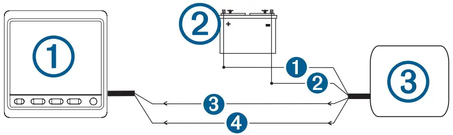
| Item | Description |
1 | Marine instrument with a NMEA data cable (not included) |
2 | Power source |
3 | NMEA 0183 compliant device |
| Item | Garmin Wire Function | Garmin Wire Color | NMEA 0183 Device Wire Function |
1 | N/A | N/A | Power |
2 | N/A | N/A | Data ground |
3 | Rx/A (In +) | Brown | Tx/A (Out +) |
4 | Rx/B (In -) | Green | Tx/B (Out -) |
This diagram is an example of a connection to a standard NMEA 0183 device with one Tx wire.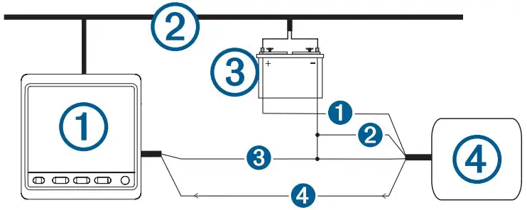
| Item | Description |
1 | Marine instrument with a NMEA data cable (not included) |
2 | NMEA 2000 network (must connect to the same ground as the NMEA data cable) |
3 | Power source |
4 | NMEA 0183 compliant device |
| Item | Garmin Wire Function | Garmin Wire Color | NMEA 0183 Device Wire Function |
1 | N/A | N/A | Power |
| Item | Garmin Wire Function | Garmin Wire Color | NMEA 0183 Device Wire Function |
2 | N/A | N/A | Power ground |
3 | Rx/B (In -) | Green | Data ground |
4 | Rx/A (In +) | Brown | Tx |
This diagram is an example of a connection to a Garmin HVS GPS antenna.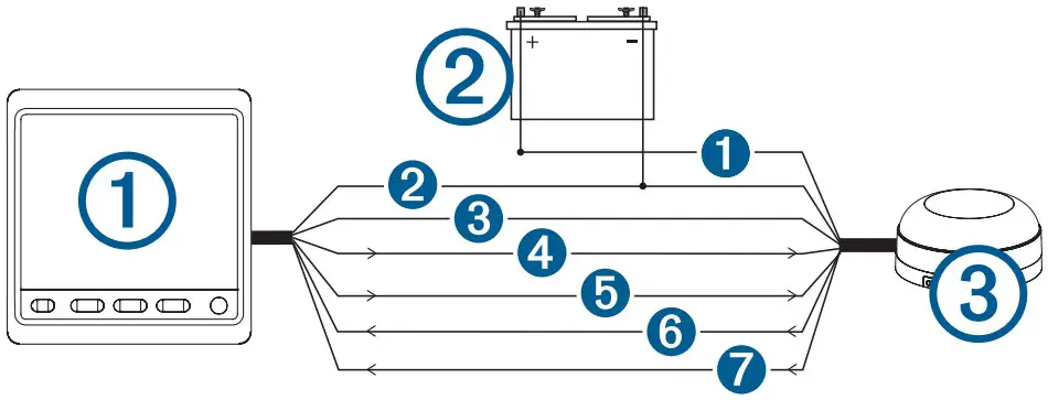
| Item | Description |
1 | Marine instrument with a NMEA data cable (not included) |
2 | Power source |
3 | Garmin HVS GPS antenna |
| Item | Marine Instrument Wire Color | Antenna Wire Color |
1 | N/A | Red |
2 | Black | Black |
3 | Yellow | Orange |
4 | Blue | White |
5 | White | White/orange |
6 | Brown | Gray |
7 | Green | White/red |
Specifications
| Specification | Measurement |
| Dimensions without sun cover (H×W×D) | 110 x 115 x 30 mm (4.33 x 4.53 x 1.18 in.) |
| Dimensions with sun cover (H×W×D) | 115 x 120 x 35.5 mm (4.53 x 4.72 x 1.40 in.) |
| Weight without sun cover | 247 g (8.71 oz.) |
| Weight with sun cover | 283 g (9.98 oz.) |
| Temperature range | From 5° to 158°F (from -15° to 70°C) |
| Compass-safe distance | 209 mm (8.25 in.) |
| Material | Case: fully-gasketed polycarbonate Lens: glass with an anti-glare finish |
| Water Resistance | IEC 60529 IPX7 1 |
| Power usage | 1.35 W max |
| Unit max. voltage | 32 Vdc |
| NMEA 2000 input voltage | From 9 to 16 Vdc |
| NMEA 2000 load equivalency number (LEN) | 3 (150 mA at 9 Vdc) |
NMEA 2000 PGN Information
Transmit and Receive
| PGN | Description |
| 059392 | ISO acknowledgment |
| 059904 | ISO request |
| 060928 | ISO address claim |
| 61184 | Product information |
| 126208 | NMEA: Command, request, and acknowledge group function |
| 126996 | Product information |
Transmit
| PGN | Description |
| 126464 | Transmit PGN list group function |
Receive
| PGN | Description |
| 126992 | System time |
| 127245 | Rudder |
| 127250 | Vessel heading |
| 127488 | Engine parameters: Rapid update |
| 127489 | Engine parameters: Dynamic |
| 127508 | Battery status |
| 128259 | Speed: Water referenced |
| 128267 | Water depth |
| 129025 | Position: Rapid update |
| 129026 | COG and SOG: Rapid update |
| 129029 | GNSS position data |
| 129283 | Cross track error |
| 129284 | Navigation data |
| 129285 | Navigation route and waypoint info |
| 129539 | GNSS dilution of precision (DOP) |
| 130306 | Wind data |
| 130310 | Environmental parameters |
| 130311 | Environmental parameters |
| 130312 | Temperature |
| PGN | Description |
| 130313 | Humidity |
| 130314 | Actual pressure |
NMEA 0183 Information
When connected to an optional NMEA 0183 compatible device, the instrument can receive these NMEA 0183 sentences.
| Sentence | Description |
| DBT | Depth below transducer |
| DTM | Datum being used |
| DPT | Depth |
| GGA | Global positioning system fix data |
| GLL | Geographic position (latitude and longitude) |
| GRMB | GPS data |
| GRME | GPS position error data |
| GSA | GNSS DOP and active satellites |
| GSV | GNSS satellites in view |
| HDG | Heading, deviation, and variation |
| HDM | Heading, magnetic |
| HDT | Heading, true |
| MDA | Meteorological composite |
| MTW | Water temperature |
| MWD | Wind direction and speed |
| MWV | Wind speed and angle |
| RMC | Recommended minimum specific GNSS data |
| THS | Heading sensor data |
| VHW | Water speed and heading |
You can purchase complete information about National Marine Electronics Association (NMEA) format and
sentences from www.nmea.org.
Support
© 2014 Garmin Ltd. or its subsidiaries
Garmin® , the Garmin logo, and Nexus® are trademarks of Garmin Ltd. or its subsidiaries, registered in the USA and other countries. GNX™ and GND™ are trademarks of Garmin Ltd. or its subsidiaries. These trademarks may not be used without the express permission of Garmin. NMEA® , NMEA 2000® , and the NMEA 2000 logo are registered trademarks of the National Marine Electronics Association.


