Unication G-Series P25 Voice Pagers Charger Amplifier User Manual


※IMPORTANT SAFETY INFORMATION
To ensure the safe use of this product:
Use your charger amplifier only with the supplied power adaptor.
Use the batteries provided by Unication for your G-Series product.
Keep your charger amplifier away from high temperature, high humidity, dust, chemicals and corrosive materials.
Do not disassemble your charger amplifier or power adaptor.
This device complies with part 15 of the FCC Rules.
Operation is subject to the following two conditions:
(1) This device may not cause harmful interference, and
(2) This device must accept any interference received, including interference that may cause undesired operation.\
OVERVIEW
A-1 Standard Package:
Standard package contains:
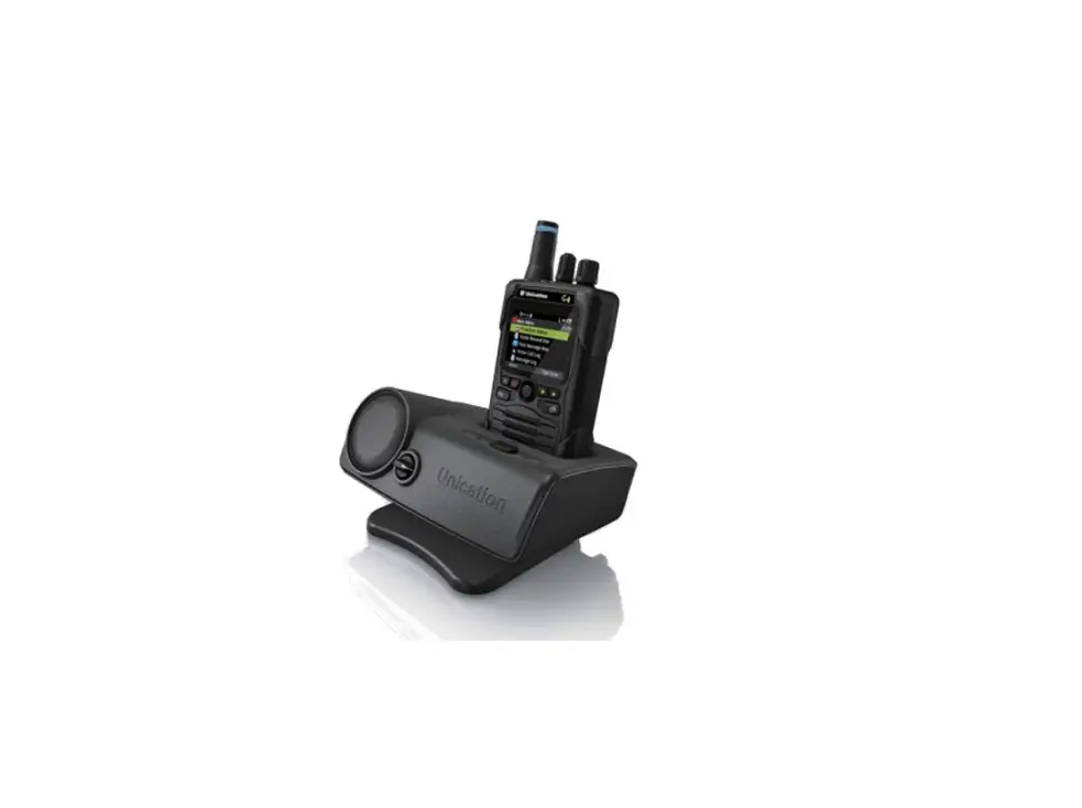
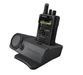
- Charger Amplifier for Digital G Series Pager

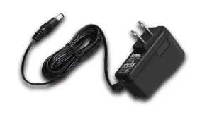
- Adaptor

- External Antenna

- Manua


A-2 Specification:
| Item Specification | ||
| Charging Type | Main Charging Socket | For one Digital G-Series Voice Pager |
| BT Charging Socket | For USB Device (BT headset supported) | |
| Power Supply | Adaptor Input / Output | Input: 100~240VAC / 50~60 Hz Output:12Vdc / 1.5A |
| Normal Charge Current | 900 mA / 5.0 V | |
| Full Recharge Time | 3 Hours | |
| SPL | Alert Output | ≧106 dBSPL |
| Speech Output | ≧104 dBSPL | |
| Audio Distortion | • Audio Distortion: Real Time Audio: < 5 % (Electrical) / < 6 % (Acoustic) • Audio Distortion: Stored-Voice Playback: < 8 % (Electrical) / < 10 % (Acoustic) | |
| External I/O | Audio Out | 3.5mm Audio Jack *1 |
| Ext. Antenna Port | BNC Jack *1 | |
| USB Charging Port | USB A-Type *1 | |
| Controller Port | RS485 (DB-9 Female) *1 | |
| Power Input (DC) | 12Vdc / 1.5A | |
| Horn Speaker Port | 4 Pin Port | |
| 6 Pin DIN Port | 6 Pin DIN Port | |
| LED Indicators | Power LED | Green |
| Charging LED | Red / Orange / Green | |
| Alarm LED | Orange / Green | |
| Horn Speaker LED | Orange / Green | |
| Physical | Dimensions | 162(L) x 115(W) x 53(H) mm |
| Weight | 600 g | |
| Handing Temperature | Operation Temperature | 0 ~ + 40°C |
| Storage Temperature | -10 ~ + 60 °C | |
| Certification | CE, FCC, RoHs, UL, CUL | |

B OVERVIEW
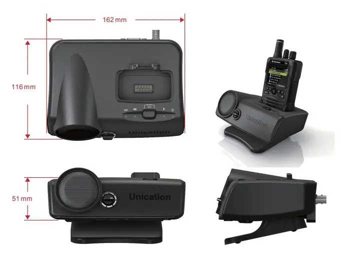
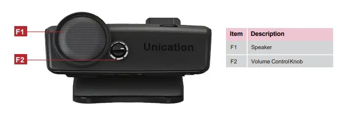
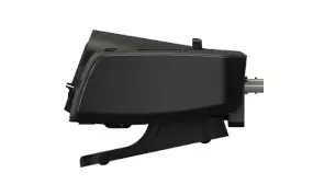
B-1 Front View:
B-2 Top View:
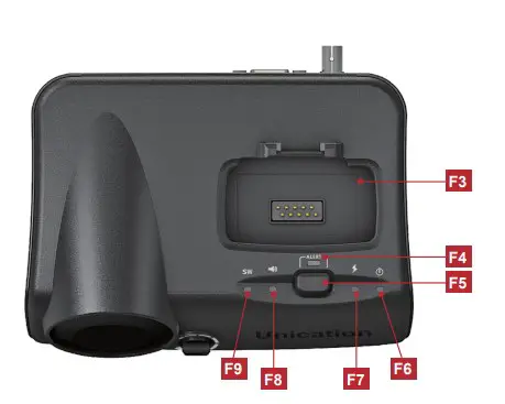
| Item | Description |
| F3 | Pager Socket |
| F4 | Alert Light |
| F5 | Reset Button |
B-3 LED Indicators:
| No. | Item | Color | LED Action | Description |
| F6 | Power LED | Green | Steady | Charger Amplifier Power Turn ON. |
| F7 | Charging LED | Orange | Steady | Pager is charging. |
| Green | Steady | Pager is fully charged. | ||
| F8 | Alarm LED | Off | Steady | Alarm device is not connected. |
| Orange | Steady | Alarm device is connected, no messages received. | ||
| Green | Steady | Alarm device is connected, receiving alarm messages. | ||
| F9 | Horn Speaker LED | Off | Horn Speaker is not connected. | |
| Orange | Steady | Horn Speaker is connected, no message received. | ||
| Green | Steady | Horn Speaker is connected, Horn Speaker message received. |
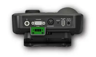
B-4 Rear View:
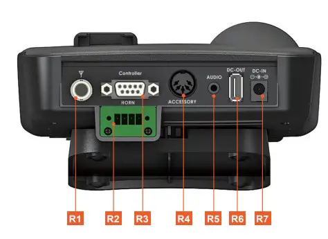
| Item | Description |
| R1 | External Antenna Port (BNC) |
| R2 | Horn Speaker 4 Pin Horn Port |
| R3 | Controller Port (RJ485) |
| R4 | Alarm Device 6 Pin Din Port |
| R5 | Audio Out |
| R6 | USB Charging Port |
| R7 | Power Input (DC) |
C OVERVIEW
1 Power Source:
Connect the Charger Amplifier to power outlet (110/60Hz) with the supplied Adaptor. Connect the Charger Amplifier to vehicle’s lighter socket with optional vehicle charger cable.
2 Charging Digital G Series Pager:
Insert Digital G Series Voice Pager into Charger Amplifier’s Pager Socket tightly. The charging process starts with Charging LED indicator shows orange. When the battery is fully charged, the LED turns green.
3 Charging USB device:
Connect the USB device to the Charger Amplifier’s USB Charging Port with USB Cable.
4 Voice Message Amplification:
Turn on Digital G Series Voice Pager and put into Charger Amplifier’s pager socket.When the pager receives voice messages, it will be amplified based on the volume knob setting.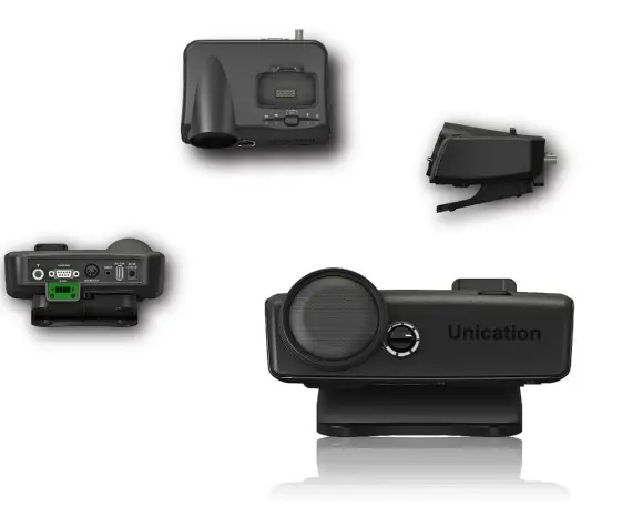
5 External Antenna Port:
Please select antenna depending on the frequency use. Unication provides the antenna options below:
UHF1 750~860 MHz
UHF2 406~512 MHz
VHF 136~174MHz
Low Band 30~88 MHz
6 Horn Speaker 4 Pin Horn Port:
PIN 1 Horn Relay Contact
PIN 2 Horn Relay Contact
PIN 3 Ground (Audio)
PIN 4 Audio*
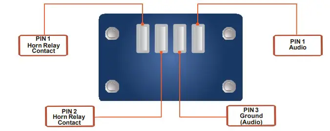
*This Connection provides line level audio not controlled by the volume knob. Using this connection will not mute the onboard speaker.
7 Controller Port: (RJ485)
The Controller Port is for external LED or Uni-controller use.
PIN 3: RS485_A
PIN 2: RS485_B
PIN 3: RS485_A
PIN 2: RS485_B

8 3.5mm Audio Jack:
This connections audio output is controlled by the volume knob on the device and mutes the onboard speaker when in use.
9 Alarm Device 6 Pin Din Port:
The Charger Amplifier for Digital G-Series Pager provides 2 modes to select via Side Switch
1. M5 Mode (default)
2. Horn Speaker Mode
DIN Jack Pin Definition:
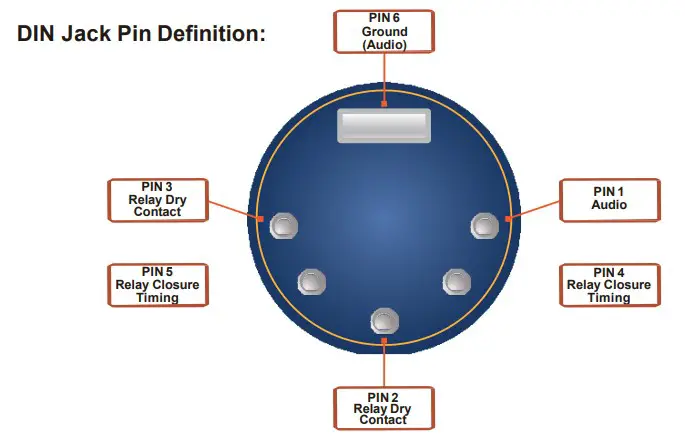
PIN 1 Audio
PIN 2 Relay Dry Contact
PIN 3 Relay Dry Contact
PIN 4 Relay Closure Timing
PIN 5 Relay Closure Timing
PIN 6 Ground (Audio)
10 USB Charging Port:
This port is for charging USB device and Bluetooth earpiece. (5V/300mA)
11 Power Input :
The Charger Amplifier for Digital G Series Pager use a 12V/1.5A DC ADAPTOR, power input is 100~240VAC with maximum power 18W. Please connect to the power
outlet with supplied power adaptor.
12 External Equipment Control
The Charger Amplifier provides a variety of I/0 for external device control.
12-1. Horn Speaker (Loudspeaker)
Step 1. Insert the G-Series Pager, turned on, into the Charger Amplifier.
Step 2. Select RCA connector and connect the external equipment.
Step 3. When any message is received, the relay closure is asserted and audio is active.
Step 4. Audio can be terminated by either shutting the G5 off or depressing the Reset button on the G5.
12-2. Fire Alert Indicator
Step 1. Insert the G-Series Pager, turned on, into the Charger Amplifier.
Step 2. Using the DIN Connector, connect the external equipment to the appropriate signaling pins.
• Pins 1 and 6 are outputs and are used to control a remote speaker.
• Pins 2 and 3 are normally open dry contacts and close when a page is received.
• Pins 4 and 5 are not utilized on the G4/G5 Amplified Charger, all timing of the dry contacts is controlled via the Pager Programing Software.
Step 3. Upon receiving a page, the relay and audio output are activated.
13 Amp Charger Connectors
G-Series Charger Amp Terminal Connector Block
Part Number: 2811923-AMP
G-Series Charger Amp Din Connector
Part Number: CP-1050-ND