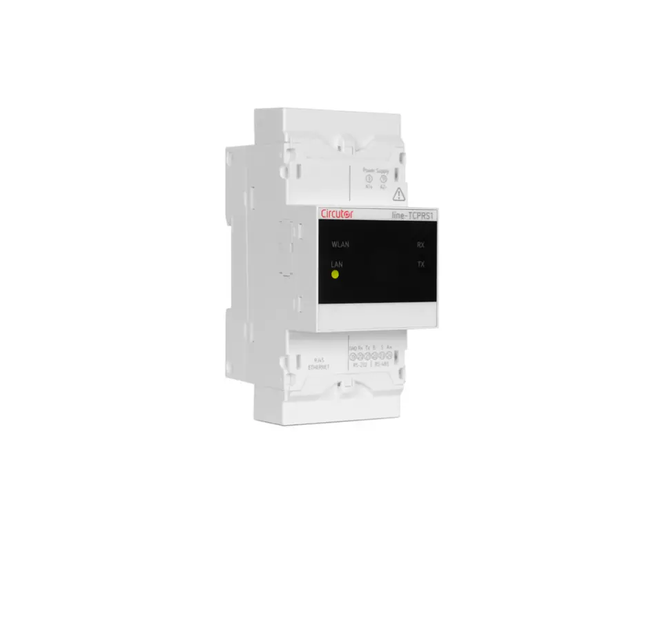
Circutor line-TCPRS1 Wireless Converter
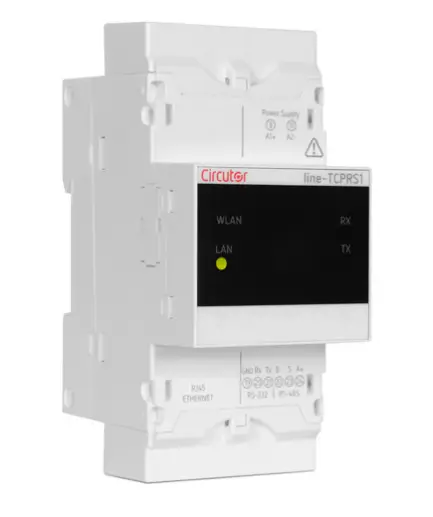
line-TCPRS1
| This manual is a line-TCPRS1 installation guide. For further information, please download the full manual from the CIRCUTOR web site: www.circutor.com |
 | IMPORTANT! |
| The device must be disconnected from its power supply sources (power supply and measurement) before undertaking any installation, repair or handling operations on the unit’s connections. Contact the after-sales service if you suspect that there is an operational fault in the device. The device has been designed for easy replacement in case of malfunction. | |
| The manufacturer of the device is not responsible for any damage resulting from failure by the user or installer to heed the warnings and/or recommendations set out in this manual, nor for damage resulting from the use of non-original products or accessories or those made by other manufacturers. |
DESCRIPTION
The line-TCPRS1 is a gateway designed to convert an RS-485 or RS-232 physical environment to Ethernet and/or Wi-Fi. The device features a Web Server and an app (Android) that uses Bluetooth connectivity, from which the user can completely edit the configuration parameters of the device. The device can be connected via the side bus to the devices of the line range, without the need to cable the communications bus, making it much easier to install. It also has RS-485 and RS-232 communication terminals so that it can be simultaneously connected to other devices not in the line range.
INSTALLATION
The device must be installed on an electric panel or enclosure, attached to a DIN rail (IEC 60715).
| IMPORTANT! |
| Take into account that when the device is connected, the terminals may be hazardous to the touch, and opening the covers or removing elements may provide access to parts that are dangerous to the touch. Do not use the device until it is fully installed. |
The device must be connected to a power circuit that is protected with gl (IEC 269) or M type fuses with a rating of 1 to 2 A. It must be fitted with a circuit breaker or equivalent device, in order to be able to disconnect the device from the power supply network. The power and voltage measuring circuit must be connected with cables that have a minimum cross-section of 1mm2. The line-TCPRS1 devices can be connected to other devices in the line range: line-CVM-D32 and the line-M-xxx-xx expansion modules.
| IMPORTANT! |
| Only 2 expansion modules can be directly connect to the right side of the device. Up to 7 devices can be connected to the right (lineCVM-D32 and line-M-xxx-xx) in installations that have a line-TCPRS1. View the manuals M237B01-03-xxx and M239B01-03xxx for further information. |
The steps to take to connect the devices are:
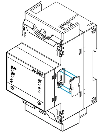
- Remove the protective covers of the expansion connector, which are located on the side of the devices, using a flat-tip screwdriver (Figure 1).
Figure 1
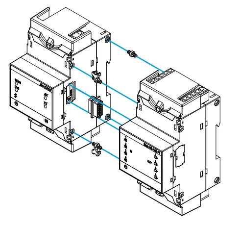
- Insert the expansion connector and fastening clips into one of the devices (Figure 2).
Figure 2
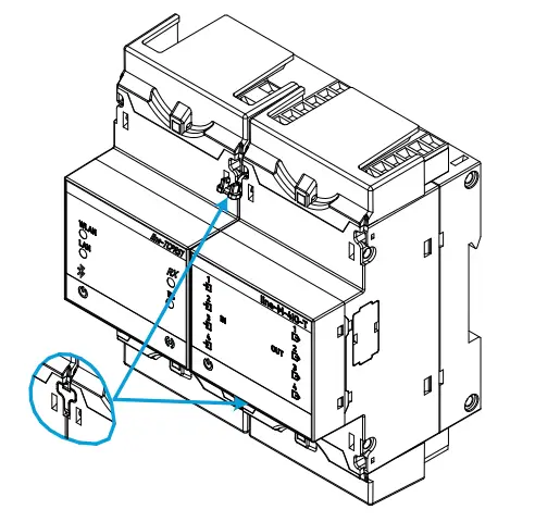
- Connect the two devices and fasten them by pushing the front clips down (Figure 3).
Figure 3
Technical features
AC Power supply | |||
| Rated voltage | 100 … 264 V~ | ||
| Frequency | 50 … 60 Hz | ||
| Consumption | 3.5 … 7.5 VA | ||
| Installation category | 3.5 … 7.5 VA | ||
DC Power supply | |||
| Rated voltage | 100 … 300 V⎓ | ||
| Consumption | 2 … 2.5 W | ||
| Installation category | CAT III 300 V | ||
RS-485 interface | |||
| Bus | RS-485 | ||
| Baud rate | 4800 – 9600 – 19200 – 38400 – 57600 – 115200 bps | ||
| Data bits | 7 -8 | ||
| Stop bits | 7 -8 | ||
| Parity | without – even – odd | ||
RS-232 interface | |||
| Bus | RS-232 | ||
| Baud rate | 4800 – 9600 – 19200 – 38400 – 57600 – 115200 | ||
| Data bits | 7 -8 | ||
| Stop bits | 1 -2 | ||
| Parity | without – even – odd | ||
Ethernet interface | |||
| Type | Ethernet 10BaseT – 100BaseTX autodetectable / self-detectable | ||
| Connector | RJ45 | ||
| Protocol | TCP – UDP – Modbus TCP – HTTP (Web server) – REST | ||
| Connection mode to Network | DHCP ON/OFF (ON / by default) | ||
Wi-Fi communication | |||
| Band | Range : 2.4 … 2.5 GHz) | ||
| Standard | IEEE 802.11 b / g , IEEE 802.11 n (hasta / up to 150 Mbps) | ||
| Max. Output power | IEEE 802.11 b : 20 dBm IEEE 802.11 n : 14 dBm | ||
Bluetooth® communication | |||
| Protocols | Bluetooth® v4.2 BR/EDR and BLE specification | ||
| Radio | NZIF receiver with –97 dBm sensitivity Class-1, class-2 and class-3 transmitter Adaptive Frequency Hopping (AFH) Receiver Sensitivity @30.8% PER -97 dBm Transmitter RF power control range Min: -12 dBm / Max: +12dBm | ||
User interface | |||
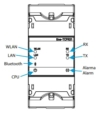
| LED | 7 LEDs | ||
Environmental features | |||
| Operating temperature | -10ºC… +50ºC | ||
| Storage temperature | -20ºC … +70ºC | ||
| Relative humidity (non-condensing) | 5 … 95% | ||
| Maximum altitude | 2000 m | ||
| Protection degree | IP30, Frontal / Front : IP40 | ||
Mechanical features | |||
| Terminals |  |  | 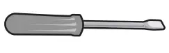 |
| 9, 11, 19 … 24 | 2.5 mm2 | ≤ 0.4 Nm, M2.5 | flat |
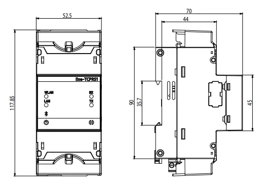
| Dimensions | 52.5 x 117.85 x 70 mm | ||
| Weight | 170 g. | ||
| Enclosure | Self-extinguishing V0 plastic | ||
| Attachment | DIN rail (1) | ||
Standers | |||
| EN 61010-1, EN 61000-6-2, EN 61000-6-4 | |||
Minimum recommended distance between DIN rails: 150 mm.
| Terminal connections designations | |
| 9 | Auxiliary power supply |
| 11 | Auxiliary power supply |
| 19(2) | for RS-4232 |
| 20(2) | Rx, RS-232 |
| 21(2) | Tx, RS-232 |
| 22(2) | B-, RS-485 |
| 23(2) | S, for RS-485 |
| 24(2) | A+, RS-485 |
| Ethernet | Ethernet connection |
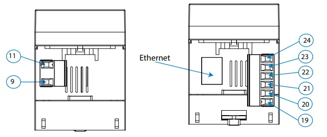
For the correct operation of serial communications, the RS-485 and RS-232 ports should not be wired at the same time.
Dimension
| LEDs | |
| CPU | Device status |
| Flashing (White color): | |
| Device powered | |
| WLAN | Wi-Fi connectivity |
| ON (Blue color): | |
| Wi-Fi connectivity enabled | |
| LAN | Ethernet connectivity |
| ON (Green color): | |
| Ethernet connectivity enabled | |
| Bluetooth | Bluetooth® connectivity |
| ON (Blue color): | |
| Bluetooth® linked | |
| RX | RS-485 / RS-232 |
| Flashing (Orange color): | |
| Frame reception | |
| TX | RS-485 / RS-232 |
| Flashing (Orange color): | |
| Frame delivery | |
| Alarm | Alarm |
| ON (Red color): | |
| Frame reception error | |
Technical service
| CIRCUTOR SAT: 902 449 459 (SPAIN) / (+34) 937 452 919 (out of Spain) Vial Sant Jordi, s/n 08232 – Viladecavalls (Barcelona) Tel: (+34) 937 452 900 – Fax: (+34) 937 452 914 e-mail : [email protected] |