DESCO 19431 Body Voltage Meter Instruction Manual
A compliance verification plan shall be established to ensure the organization’s fulfilment of the requirements of the plan. Process monitoring (measurements) shall be conducted in accordance with a compliance verification plan that identifies the technical requirements to be verified, the measurement limits and the frequency at which those verifications shall occur. The compliance verification plan shall document the test methods used for process monitoring and measurements. If the organization uses different test methods to replace those of this standard, the organization shall be able to show that the results achieved correlate with the referenced standards. Where test methods are devised for testing items not covered in this standard, these shall be adequately documented including corresponding test limits. Compliance verification records shall be established and maintained to provide evidence of conformity to the technical requirements. The test equipment selected shall be capable of making the measurements defined in the compliance verification plan.” (EN 61340-5-1 clause 5.2.4)
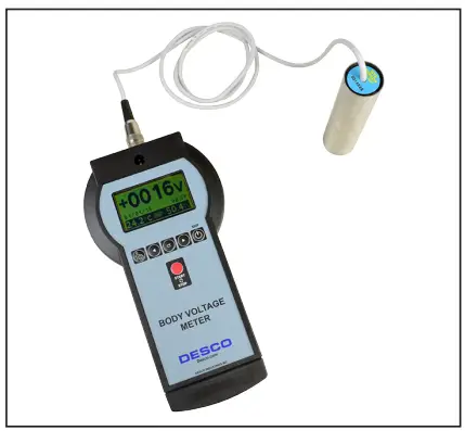
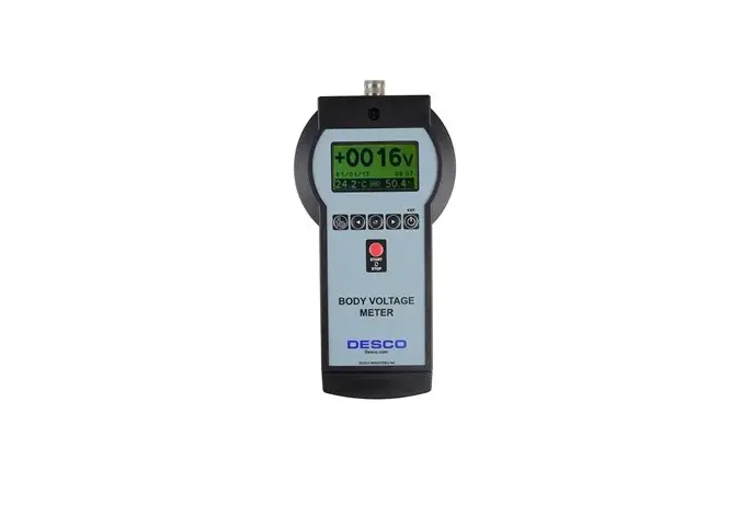
Figure 1. Desco 19431 Body Voltage Meter
Description
The Desco 19431 Body Voltage Meter is a portable measuring system that allows analysis of charge levels accumulated on the human body according to IEC 61340-4-5. It is fully portable and does not require a PC for data acquisition as all data is measured and logged using internal memory. The operator can perform all necessary tests without another user, and while walking the instrument is attached only with a single cable to a fixed position for reference to ground. Graphs of tests can be displayed on the LCD display for quick evaluation. They can also be exported and analysed on a PC for professional record-keeping.
Each Body Voltage Meter is calibrated with accepted procedures and standards traceable to the National Institute of Standards and Technology (NIST) and includes a NIST certificate.
Packaging
- 1 Body Voltage Meter
- 1 Walking Test Probe
- 1 Black 8-Pin DIN to USB Cable, 1.8 m long
- 1 Black Ground Cord with Crocodile Clip, 5 m long
- 1 Lanyard with Hook
- 1 Certificate of Calibration
Features and Components
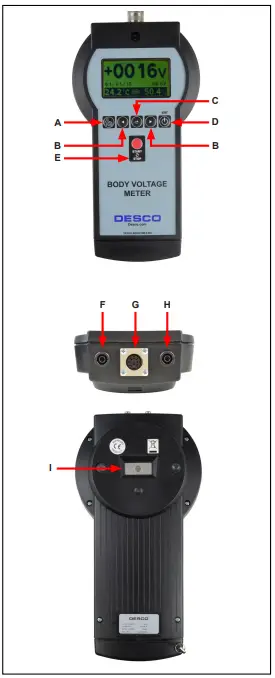
Figure 2. Body Voltage Meter features and components
A. Settings Button: Press to enter SETTINGS mode.
B. Left and Right Buttons: Press to cycle through the menus.
C. Cursor Button: Press to advance the cursor.
D. Exit Button: Press to power the meter ON and OFF.
This button is also used to exit SETTINGS and MENU modes.
E. Start / Stop Button: Press to start and stop a measurement. This button is also used to increase the value of settings when in SETTINGS mode.
F. Ground Jack: Common point ground for the meter.
Connect the included black ground cord here.
G.Probe / PC Connector: Connect the included test probe when taking measurements. Connect the included DIN to USB cable when exporting data onto a PC.
H. Ground Jack: Common point ground for the meter. Connect the included black ground cord here.
I. Ground Touch Plate: Touch to ground the operator prior to taking body voltage measurements.
Settings Mode
Press and hold the Settings button for 1 second to enter
the SETTINGS mode. There are 4 menus available:
- V RANGE
- CLOCK
- DISPLAY
- °C/°F
Press the Left button to move to the previous menu.
Press the Right button to move to the next menu.
Press the Exit button to exit from SETTINGS mode.
V. Range Menu

Adjust the voltage range for new and saved graphs.
Press the Cursor button to advance the cursor, and
press the Start / Stop button to increase the value.
NOTE: AUTO range is only available for saved graphs
Clock Menu
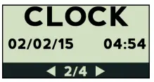
Adjust the date and time settings. Press the Cursor button to advance the cursor, and press the Start / Stop button to increase the value.
Display Menu

Adjust the contrast of the LCD display (0 to 9). The default contrast setting is 5. Press the Start / Stop button to increase the value.
°C/°F Menu
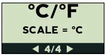
Choose Celsius (° C) or Fahrenheit (° F) for the temperature unit of measurement. Press the Start / Stop button to toggle the setting.
Operation Modes
There are 5 operation modes available:
- MONITOR
- NEW
- VIEW
- CLEAR
- COM
Press the Left button to move to the previous mode.
Press the Right button to move to the next mode.
Press the Start / Stop button to enter the selected mode.
Press the Exit button to exit the selected mode.
Monitor Mode

Allows on-the-go measurements without saving any data.
New Mode
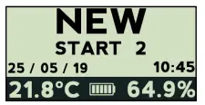
Records new graph.
View Mode
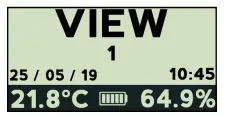
Views saved graphs.
Clear Mode
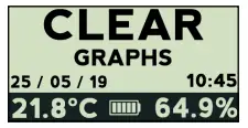
Deletes last or all saved graphs.
COM Mode
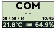
Exports data to PC using supplied 8-Pin DIN to USB cable.
Installation
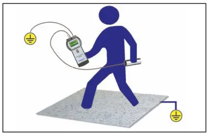
Figure 3. Setup of the Body Voltage Meter
- Remove the meter from the carton.
- Connect the included ground cord to one of the two ground jacks located at the top of the meter. Connect the opposite end of the ground cord to equipment ground.
- Connect the test probe to the probe connector located at the top of the meter.
- Press the EXIT button to power the meter.
- The meter is now ready for use.
Operation
Using the Meter
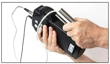
- Press the EXIT button to power the meter.
- Hold the test probe and momentarily touch the ground touch plate located on the back of the unit.

Figure 4. Momentarily touching the ground touch plate to ground the operator. - Verify the Body Voltage Meter is zeroed by toggling to the MONITOR menu and reading the measured value. It should be 0 V. Zero the Meter if required by toggling to the ZERO menu.

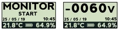
Monitor Mode
- Toggle to MONITOR mode on the meter, and press the Start / Stop button.
- The display will show the electrical potential present on the probe.

- A beeping sound (every second) indicates that the meter is measuring. This is to ensure the unit is not left in measuring mode unintentionally and cause the battery to drain.
- To stop the measuring process, press the Start / Stop or Exit buttons.
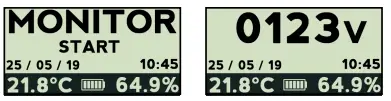
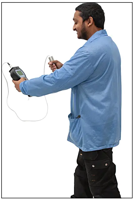
Figure 5. Using the Body Voltage Monitor
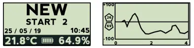
Datalogger Mode
- Toggle to NEW mode on the meter and press the Start / Stop button.
- After a 3 second count-down, the Body Voltage Monitor will log a graph of the walking test.
- The graph will show the positive and negative peak voltages measured during the test.

- To stop the test, press the Start / Stop button.
- Press the Left or Right buttons to scroll through the graph for quick evaluation.
- Press the Start / Stop button again to save or discard the graph. Press Start / Stop button to save or the Cursor button and Start / Stop button to discard the graph.
Connecting the Body Voltage Meter to a PC
- Download the Windows RS232 Driver.
- Open the folder with the correct operating system being used on the PC.
- Run the CDM21226_Setup.
- Once installation is complete, restart the PC.
- Download and install the WT Manager software.
- Connect the Body Voltage Meter to a PC using the included Black 8-Pin DIN to USB Cable.
- Toggle to COM mode on the Body Voltage Meter.
- Run WTManager1.3.3.
- Click on Datalogger.
- Click on Com Port select.
- Click on Port. The COM selection for the Body Voltage Monitor will become visible.
- When selected, the unit will be highlighted.
- Click OK.
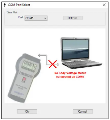
Figure 6. Selecting a COM port using the WT Manager software
Importing Data into a PC
- Select Import Graph. A progess bar will appear at the bottom of the screen.
- Data can either be saved or exported in Excel format.
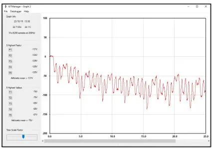
Figure 7. Viewing the body voltage of an ungrounded operator in the WT Manager software
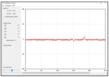
Figure 8. Viewing the body voltage of a grounded operator in the WT Manager software.
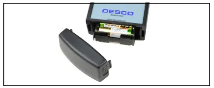
Figure 9. Replacing the Batteries on the Body Voltage Meter
Specifications
| Voltage Range | ±1050 V |
| Accuracy | ±5 V for values below 100 V ±5 % for values 100 V and above |
| Resolution | 1 V |
| Input Resistance | 1014 ohms |
| Power Supply | 6 AA alkaline batteries |
| Battery Auto-Shut Off Timer | 10 minutes |
| Display | Graphic LCD 128 x 64 pixel, 68 mm x 51 mm |
| Memory Capacity | 10 graphs |
| Sample Rate | 200 Hz |
| Max Total Graphs Duration | 2 minutes and 30 seconds |
| PC Interface | USB |
| Operating Temperature | 41 ºF to 85 ºF (5 ºC to 30 ºC) |
| Environmental Requirements | Indoor use only at altitudes less than 6500 ft. (2 km) Maximum relative humidity of 80 % up to 85 °F (30 °C) |
| Dimensions (meter) | 9.6″ x 5.1″ x 2.4″ (243 mm x 130 mm x 60 mm) |
| Dimensions (probe) | Ø 1.4″ x 5.1″ (Ø35 mm x 130 mm |
| Weight (meter with batteries) | 1.4 lbs (650 g |
| Weight (probe) | 0.6 lbs (250 kg) |
| Country of Origin | Italy |
Limited Warranty
Limited Warranty, Warranty Exclusions, Limit of Liability and RMA Request Instructions See the Desco Europe Warranty –
DescoEurope.com/Limited-Warranty.aspx
DESCO EUROPE – 2A DUNHAMS LANE, LETCHWORTH, HERTFORDSHIRE, SG6 1BE, UK
Phone: +44 (0) 1462 672005 • E-mail: [email protected], Website: DescoEurope.com


