
FIBARO
FIBARO CO Sensor
SKU: FIBEFGCD-001


Quickstart
This is a
secure
CO Detector
for
Europe.
To run this device please insert fresh 1 * CR123A batteries.
Please make sure the internal battery is fully charged.
Important safety information
Please read this manual carefully. Failure to follow the recommendations in this manual may be dangerous or may violate the law.
The manufacturer, importer, distributor and seller shall not be liable for any loss or damage resulting from failure to comply with the instructions in this manual or any other material.
Use this equipment only for its intended purpose. Follow the disposal instructions.
Do not dispose of electronic equipment or batteries in a fire or near open heat sources.
What is Z-Wave?
Z-Wave is the international wireless protocol for communication in the Smart Home. This
device is suited for use in the region mentioned in the Quickstart section.

Z-Wave ensures a reliable communication by reconfirming every message (two-way
communication) and every mains powered node can act as a repeater for other nodes
(meshed network) in case the receiver is not in direct wireless range of the
transmitter.
This device and every other certified Z-Wave device can be used together with any other
certified Z-Wave device regardless of brand and origin as long as both are suited for the
same frequency range.
If a device supports secure communication it will communicate with other devices
secure as long as this device provides the same or a higher level of security.
Otherwise it will automatically turn into a lower level of security to maintain
backward compatibility.
For more information about Z-Wave technology, devices, white papers etc. please refer
to www.z-wave.info.
Product Description
Prepare for Installation / Reset
Please read the user manual before installing the product.
In order to include (add) a Z-Wave device to a network it must be in factory default
state. Please make sure to reset the device into factory default. You can do this by
performing an Exclusion operation as described below in the manual. Every Z-Wave
controller is able to perform this operation however it is recommended to use the primary
controller of the previous network to make sure the very device is excluded properly
from this network.
Reset to factory default
This device also allows to be reset without any involvement of a Z-Wave controller. This
procedure should only be used when the primary controller is inoperable.
Safety Warning for Batteries
The product contains batteries. Please remove the batteries when the device is not used.
Do not mix batteries of different charging level or different brands.
Installation
READ BEFORE INSTALLATION” AND HEED ALL THE WARNINGS!
• The device should be cleaned with a slightly damp cloth or moistened” tissue.
Note: Recommended height of installation is dependant on the purpose of the room and height at which head typically is.
Place of installation: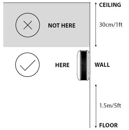
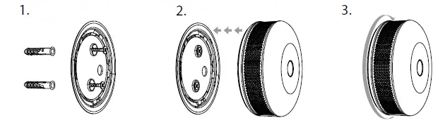
Installation on the wall:
Inclusion/Exclusion
On factory default the device does not belong to any Z-Wave network. The device needs
to be added to an existing wireless network to communicate with the devices of this network.
This process is called Inclusion.
Devices can also be removed from a network. This process is called Exclusion.
Both processes are initiated by the primary controller of the Z-Wave network. This
controller is turned into exclusion respective inclusion mode. Inclusion and Exclusion is
then performed doing a special manual action right on the device.
Inclusion
Exclusion
Product Usage
5. Press the B-Button to confirm selection.
4. Move away from the device to protect your hearing.
Note: If the self-test procedure does not result in emitting sound” and red light signal, replace the device.
Communication to a Sleeping device (Wakeup)
This device is battery operated and turned into deep sleep state most of the time
to save battery life time. Communication with the device is limited. In order to
communicate with the device, a static controller C is needed in the network.
This controller will maintain a mailbox for the battery operated devices and store
commands that can not be received during deep sleep state. Without such a controller,
communication may become impossible and/or the battery life time is significantly
decreased.
This device will wakeup regularly and announce the wakeup
state by sending out a so called Wakeup Notification. The controller can then
empty the mailbox. Therefore, the device needs to be configured with the desired
wakeup interval and the node ID of the controller. If the device was included by
a static controller this controller will usually perform all necessary
configurations. The wakeup interval is a tradeoff between maximal battery
life time and the desired responses of the device. To wakeup the device please perform
the following action:
Click the button.
Quick trouble shooting
Here are a few hints for network installation if things dont work as expected.
- Make sure a device is in factory reset state before including. In doubt exclude before include.
- If inclusion still fails, check if both devices use the same frequency.
- Remove all dead devices from associations. Otherwise you will see severe delays.
- Never use sleeping battery devices without a central controller.
- Dont poll FLIRS devices.
- Make sure to have enough mains powered device to benefit from the meshing
Association – one device controls an other device
Z-Wave devices control other Z-Wave devices. The relationship between one device
controlling another device is called association. In order to control a different
device, the controlling device needs to maintain a list of devices that will receive
controlling commands. These lists are called association groups and they are always
related to certain events (e.g. button pressed, sensor triggers, …). In case
the event happens all devices stored in the respective association group will
receive the same wireless command wireless command, typically a ‘Basic Set’ Command.
Association Groups:
Group NumberMaximum NodesDescription
| 1 | 1 | Lifeline – reports the device status and allows” for assigning single device only (main controller by default). |
| 2 | 5 | CO Alarm – is assigned to the device status” – devices in this group will be switched on/off when CO Alarm status” changes. |
| 3 | 5 | CO Alarm – is assigned to the device status” – devices in this group will receive notification when CO Alarm status” changes. Useful for devices that can trigger alarms. |
| 4 | 5 | CO Level – is assigned to measured CO level” – devices in this group will be switched on/off after exceeding the” level of CO concentration specified in parameter 14. |
| 5 | 5 | Tamper Alarm – is assigned to the tamper -” sends tamper alarm and cancellation frames to the associated devices. |
| 6 | 5 | CO Alarm BC – is assigned to the device” status – devices in this group will be switched on/off when CO Alarm” status changes. Provides backward compatibility with controllers not” supporting Z-Wave+ protocol. |
| 7 | 5 | Tamper Alarm BC – is assigned to the tamper” – sends tamper alarm and alarm cancellation frames to the associated” devices. Provides backward compatibility with controllers not” supporting Z-Wave+ protocol. |
Configuration Parameters
Z-Wave products are supposed to work out of the box after inclusion, however
certain configuration can adapt the function better to user needs or unlock further
enhanced features.
IMPORTANT: Controllers may only allow configuring
signed values. In order to set values in the range 128 … 255 the value sent in
the application shall be the desired value minus 256. For example: To set a
parameter to 200 it may be needed to set a value of 200 minus 256 = minus 56.
In case of a two byte value the same logic applies: Values greater than 32768 may
needed to be given as negative values too.
Parameter 2: Z-Wave notifications
This parameter allows to set the actions which result in sending notifications” to the Z-Wave network controller.”
Size: 1 Byte, Default Value: 0
SettingDescription
| 0 | both actions disabled |
| 1 | tampering (opened casing) |
| 2 | exceeding the temperature |
| 3 | both actions enabled |
Parameter 3: LED diode indications
This parameter allows to set the actions which result in LED diode” indications. This parameter does not apply to the most important actions,” such as CO Alarm, Malfunction Alarm and Low Battery Alarm.
NOTE:” Parameter values” may be combined, e.g.” 1+2+4=7 means that” all actions will be active.
Size: 1 Byte, Default Value: 0
SettingDescription
| 0 | all actions disabled |
| 1 | tampering (opened casing) |
| 2 | exceeding the temperature |
| 3 | lack of Z-Wave range |
Parameter 4: Acoustic signals
This parameter allows to set the actions which result in acoustic signals.” This parameter does not apply to the most important actions,” such as CO Alarm, Malfunction Alarm and Low Battery Alarm.
NOTE:” Parameter values” may be combined, e.g.” 1+2+4=7 means that” all actions will be active.
Size: 1 Byte, Default Value: 0
SettingDescription
| 0 | all actions disabled |
| 1 | tampering (opened casing) |
| 2 | exceeding the temperature |
| 3 | lack of Z-Wave range |
Parameter 7: Associations in Z-Wave network security mode
Parameter defines how commands are sent in specified association” groups: as secure or non-secure. Parameter is active only in Z-Wave network” security mode. It does not apply to 1st “Lifeline†association group.
Parameter values” may be combined,” e.g. 1+2=3 means that” 2nd & 3rd group are” sent as secure.
Size: 1 Byte, Default Value: 63
SettingDescription
| 1 | 2nd group sent as secure |
| 2 | 3rd group sent as secure |
| 4 | 4th group sent as secure |
| 8 | 5th group sent as secure |
| 16 | 6th group sent as secure |
| 32 | 7th group sent as secure |
Parameter 10: Commands sent to 2nd association group (CO Alarm)
This parameter defines commands sent to devices associated in 2nd” association group (CO Alarm). Values of specified commands may be” set in parameters 11 and 12.
Size: 1 Byte, Default Value: 3
SettingDescription
| 1 | BASIC ON |
| 2 | BASIC OFF |
| 3 | BASIC ON & BASIC OFF |
Parameter 11: Value of BASIC ON command sent to 2nd association group
This parameter defines the value of BASIC ON command sent to devices” in 2nd association group after the CO Alarm activation.
Size: 2 Byte, Default Value: 255
SettingDescription
| 0 – 99 | Value |
| 255 | turn on |
Parameter 12: Value of BASIC OFF command sent to 2nd association group
This parameter defines the value of BASIC OFF command sent to devices” in 2nd association group after the CO Alarm cancellation.
Size: 2 Byte, Default Value: 0
SettingDescription
| 0 – 99 | Value |
| 255 | turn on |
Parameter 13: Commands sent to 4th association group (CO Level)
This parameter defines commands sent to devices associated in 4th” association group (CO Level). Values of specified commands may be” set in parameters 16 and 19.
Size: 1 Byte, Default Value: 3
SettingDescription
| 1 | BASIC ON |
| 2 | BASIC OFF |
| 3 | BASIC ON & BASIC OFF |
Parameter 14: CO level required for sending BASIC ON command to 4th association group
This parameter defines the minimum level of CO concentration which” exceeding will result in starting the timer set in parameter 15.
NOTE:” Parameter 14 value” must be at least 5 ppm” higher than parameter 17 value.
Size: 2 Byte, Default Value: 40
SettingDescription
| 20 – 400 | CO concentration level in ppm |
Parameter 15: Time required for sending BASIC ON command to 4th association group
This parameter defines the time during which the level of CO concentration” should remain above the value set in parameter 14 to send the” BASIC ON command to 4th association group.
Size: 2 Byte, Default Value: 0
SettingDescription
| 0 | immediate sending of BASIC ON command |
| 1 – 2880 | (30s – 24h, in 30s steps) |
Parameter 16: Value of BASIC ON command sent to 4th association group
This parameter defines the value of BASIC ON command sent to devices in 4th association group after exceeding the CO level set in parameter 14 through the time set in parameter 15.
Size: 2 Byte, Default Value: 255
SettingDescription
| 0 – 99 | Value |
| 255 | turn on |
Parameter 17: CO Level required for sending BASIC OFF command to 4th association group
This parameter defines the maximum level of CO concentration below” which falling will result in starting the timer set in parameter 18.
Parameter 17 value ” must be at least 5 ppm” lower than parameter” 14 value.
Size: 2 Byte, Default Value: 25
SettingDescription
| 10 – 400 | CO concentration level in ppm |
Parameter 18: Time required for sending BASIC OFF command to 4th association group
This parameter defines the time during which the level of CO concentration” should remain below the value set in parameter 17 to send the” BASIC OFF command to 4th association group.
Size: 2 Byte, Default Value: 0
SettingDescription
| 0 | immediate sending of BASIC OFF command |
| 1 – 2880 | (30s – 24h, in 30s steps) |
Parameter 19: Value of BASIC OFF command sent to 4th association group
This parameter defines the value of BASIC OFF command sent to devices” in 4th association group after falling below the CO level set in” parameter 17 through the time set in parameter 18.
Size: 2 Byte, Default Value: 0
SettingDescription
| 0 – 99 | Value |
| 255 | turn on |
Parameter 20: Temperature reporting time interval
Time interval (in seconds) between consecutive reports of temperature” (done by built-in temperature sensor). Short time interval means more” frequent communication, which results in shortened battery life.
Size: 2 Byte, Default Value: 0
SettingDescription
| 0 | no periodical reports |
| 10 – 2880 | (5min – 24h, in 30s steps) |
Parameter 21: Temperature reporting hysteresis
This parameter defines a minimum change in temperature resulting” in a report being sent to the main Z-Wave controller.
Size: 1 Byte, Default Value: 2
SettingDescription
| 1 – 20 | (0.5″°C – 10″°C, each 0.5″°C) |
Parameter 22: Threshold of exceeding the temperature
This parameter defines the temperature level, which exceeding will” result in sending actions set in parameters 2, 3 and 4.
Size: 1 Byte, Default Value: 55
SettingDescription
| 1 – 85 | (1″°C – 85″°C, each 1″°C) |
Parameter 23: CO meter activation
This parameter activates reporting the value of CO concentration level” to the main Z-Wave controller.
Size: 1 Byte, Default Value: 1
SettingDescription
| 0 | disabled |
| 1 | enabled |
Parameter 25: CO level reporting hysteresis
This parameter defines a minimum change in CO concentration level” which results in sending a new value to the main Z-Wave controller.
Size: 1 Byte, Default Value: 2
SettingDescription
| 2 – 6 | (10 ppm – 30 ppm, each 5 ppm) |
Parameter 26: Threshold of CO meter activation
This parameter defines the CO concentration level, which exceeding” will result in sending a new value to the main Z-Wave controller, according” to parameter 25 settings. Adjusting the value allows to get” the accurate data in case of danger and helps to save the battery in” normal conditions.
Size: 2 Byte, Default Value: 30
SettingDescription
| 10 – 255 | ppm |
Technical Data
| Dimensions | 65×28 mm |
| Weight | 41 gr |
| Hardware Platform | ZM5202 |
| EAN | 5902020528838 |
| IP Class | IP 20 |
| Battery Type | 1 * CR123A |
| Device Type | CO Detector |
| Firmware Version | 03.00 |
| Z-Wave Version | 04.26 |
| Certification ID | ZC10-17055584 |
| Z-Wave Product Id | 0x010f.0x1201.0x1000 |
| Frequency | Europe – 868,4 Mhz |
| Maximum transmission power | 5 mW |
Supported Command Classes
- Basic
- Application Status
- Sensor Multilevel
- Crc 16 Encap
- Association Grp Info
- Device Reset Locally
- Zwaveplus Info
- Configuration
- Alarm
- Manufacturer Specific
- Powerlevel
- Firmware Update Md
- Battery
- Wake Up
- Association
- Version
- Multi Channel Association
- Security
- Sensor Alarm
Explanation of Z-Wave specific terms
- Controller — is a Z-Wave device with capabilities to manage the network.
Controllers are typically Gateways,Remote Controls or battery operated wall controllers. - Slave — is a Z-Wave device without capabilities to manage the network.
Slaves can be sensors, actuators and even remote controls. - Primary Controller — is the central organizer of the network. It must be
a controller. There can be only one primary controller in a Z-Wave network. - Inclusion — is the process of adding new Z-Wave devices into a network.
- Exclusion — is the process of removing Z-Wave devices from the network.
- Association — is a control relationship between a controlling device and
a controlled device. - Wakeup Notification — is a special wireless message issued by a Z-Wave
device to announces that is able to communicate. - Node Information Frame — is a special wireless message issued by a
Z-Wave device to announce its capabilities and functions.


