![]()
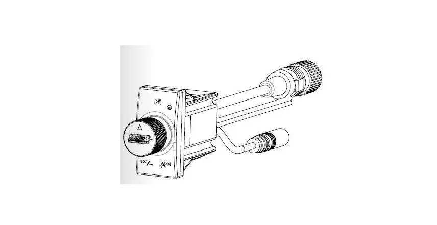
MeTra MPS-BTK1 Bluetooth Audio Receiver
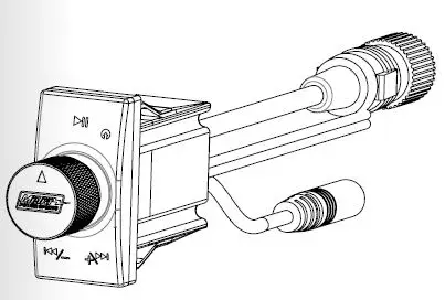
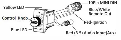
Connection Diagram
WARNING -When attaching RED ignition wire you will by-pass the internal On/Off switch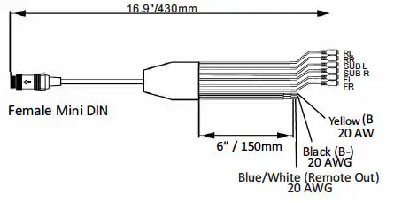
Turning Unit – ON/ OFF
- Connect yellow wire (Power +12v) and black wire (Ground -12v) wire to power and ground securely.
- Press the control knob and hold it for over 3 seconds until you see the blue LED light goes out (OFF) or stays lit for (ON).
Function Guide
| Instruction | Duration |
| Tap | Press once briefly |
| Turn | Turn knob once briefly |
| Turn and Hold | Turn knob and hold it for 3 seconds |
| Press and Hold | Press the knob and keep it pressed in for 3 seconds |
Operation Guide
| Turn On and Off | Press and Hold |
| Play/Pause music | Tap knob once to pause, tab again to resume playing |
| Skip one track forward | Turn the knob clockwise |
| Skip one track back | Turn the knob counter-clockwise |
| Adjust volume up | Turn and Hold the knob clockwise |
| Adjust volume down | Turn and Hold the knob counter-clockwise |
| Switch between Bluetooth and auxiliary input | Double Tap |
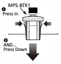
Mounting Diagram
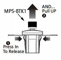
Removal Diagram
Pairing Bluetooth® Device
- Go to Settings on your smartphone and place Bluetooth ® into discoverable mode
- Search for MPS-BTK device
- On phone select MPS-BTK to pair device
- Once a device is paired each time the device is seen by the MPS-BTK it will automatically reconnect to the device. If no paired device is present, the MPS-BTK will go into discoverable mode and can be connected by another device
REMOTE IN Wiring Connection
For the following, the “YELLOW” wire must be connected to a constant +12 volt source of the vehicle. While the “BLACK” wire must be connected to a vehicle grounded source/chassis.
- If using the MPS-BTK with a head-unit, connect MPS-BTK ” RED” wire to head-unit’s “REMOTE OUT” wire (This is typically a “BLUE WITH WHITE STRIPE” wire on most head units)
- If using the MPS-BTK with vehicle’s ON/OFF key/switch, connect MPS-BTK “RED” wire to vehicle’s ignition wire.
NOTE: When connecting MPS-BTK wiring to vehicle wiring, remember to fuse connection for added protection.
- If using the MPS-BTK with desire to have controller be able to be turned ON/OFF
at any time (whether vehicle or head-unit is powered up or not), DO NOT connect the “RED” wire to any other wire. Simply ensure end of wire is tapped off to not make connection with any other wiring inside of harness .
REMOTE OUT Wiring Connection
- If using the MPS-BTK to power up an amplifier, or other device’s “REMOTE IN” wire, connect “BLUE WITH WHITE STRIPE ” (from the MPS-BTK) to the amplifier remote IN terminal or other device’s “REMOTE IN” wire (this can be “BLUE WITH WHITE STRIPE ‘, ” RED”, or other wire designated by that manufacture)


