
Heatit (Thermo-Floor)
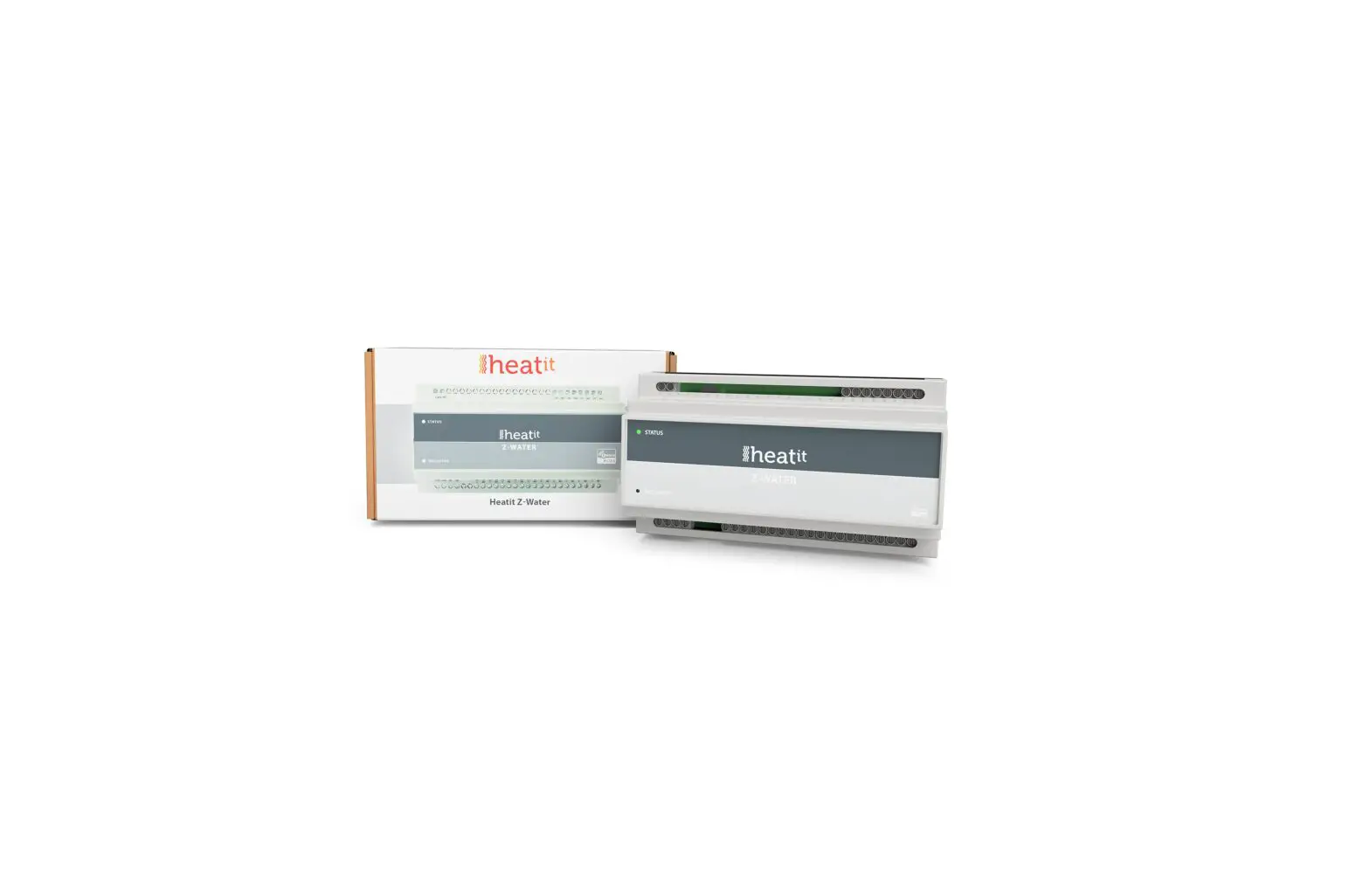
Heatit Z-Water
SKU: HEAE4512475


Quickstart
This is a
secure
Valve
for
Europe.
Please make sure the internal battery is fully charged.
Please refer to your primary controller manual on how to enteradd mode. The device can only be added from the network if the primary controller is in add mode.When the primary controller is set to add modus pressthe INCLUSION button once on the device.
Important safety information
Please read this manual carefully. Failure to follow the recommendations in this manual may be dangerous or may violate the law.
The manufacturer, importer, distributor and seller shall not be liable for any loss or damage resulting from failure to comply with the instructions in this manual or any other material.
Use this equipment only for its intended purpose. Follow the disposal instructions.
Do not dispose of electronic equipment or batteries in a fire or near open heat sources.
What is Z-Wave?
Z-Wave is the international wireless protocol for communication in the Smart Home. This
device is suited for use in the region mentioned in the Quickstart section.

Z-Wave ensures a reliable communication by reconfirming every message (two-way
communication) and every mains powered node can act as a repeater for other nodes
(meshed network) in case the receiver is not in direct wireless range of the
transmitter.
This device and every other certified Z-Wave device can be used together with any other
certified Z-Wave device regardless of brand and origin as long as both are suited for the
same frequency range.
If a device supports secure communication it will communicate with other devices
secure as long as this device provides the same or a higher level of security.
Otherwise it will automatically turn into a lower level of security to maintain
backward compatibility.
For more information about Z-Wave technology, devices, white papers etc. please refer
to www.z-wave.info.
Product Description
Heatit Z-Water is equipped with 10 relay outputs and 4 analog inputs, and a Z-Wave radio for interfacing to the wirelessZ-Wave network.The regulator can be power supplied from a 230V AC mains connection, and is able to deliver an output supply of 24V DC.Heatit Z-Water relay outputs are able to be freely controlled from the Z-Wave network, and can be used for severalpurposes, e.g. on/off control of light, control of valve actuators for an underfloor heating system, or control of other homeautomation systems.Heatit Z-Water inputs are analog inputs for interfacing simple temperature sensors; NTC, PT1000, etc.It is possible to configure the level and the indication of the status indicator LED in the front of the Heatit Z-Waterregulator.
Prepare for Installation / Reset
Please read the user manual before installing the product.
In order to include (add) a Z-Wave device to a network it must be in factory default
state. Please make sure to reset the device into factory default. You can do this by
performing an Exclusion operation as described below in the manual. Every Z-Wave
controller is able to perform this operation however it is recommended to use the primary
controller of the previous network to make sure the very device is excluded properly
from this network.
Reset to factory default
This device also allows to be reset without any involvement of a Z-Wave controller. This
procedure should only be used when the primary controller is inoperable.
Installation
Use the following procedure to install Heatit Z-Water:
3. Tilt the bottom of the Heatit Z-Water toward the DIN rail until it snaps into place.
Note: When mounting DIN Rail products, use a flathead screwdriver to pull the DIN Rail release tab while snapping the device on to the DIN Rail.
Preparing and connecting wires
Tighten the connector to 0.5 Nm. The wire gauge should be 12 to 30 AWG.
Connections
In the drawing below is the different module connections shown.
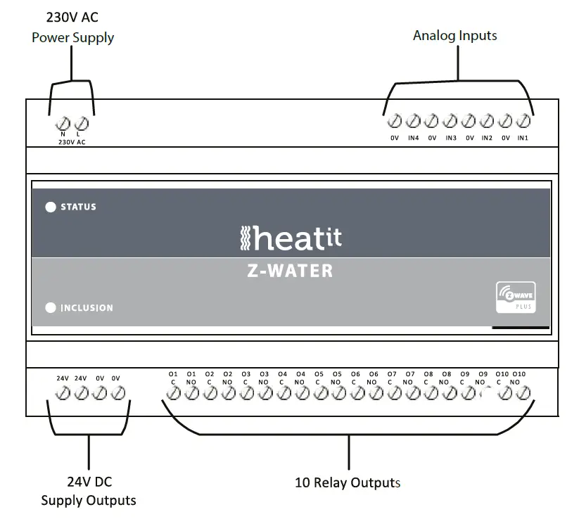
Terminals for connecting the 230V AC mains power supply. The module has an internal fuse that can be replaced by opening the cover of the module.
Fuse: 3.15A Quick-Acting, UMF 250 Schurter Inc., part no.: 3405.0171.11
Analog Inputs
Terminals for the 4 analog inputs.
24V DC Supply Outputs
Terminals for the 24V DC power supply output that can be used to be switched through the relay outputs.
Inputs
are supplied in the configuration parameters for the input, then the input will be able to be used as a temperature measuring” input, and the sensor devices in Heatit Z-Water will be able to report the temperatures as Multilevel Sensor values.
See configuration parameters 3, 4, 5 and 6.
Relay Output
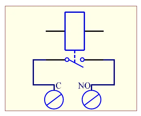
Schematic outlines of how the relay outputs are implemented internally.
24 V DC Output
24V DC output – Maximum 1.17A, 28W
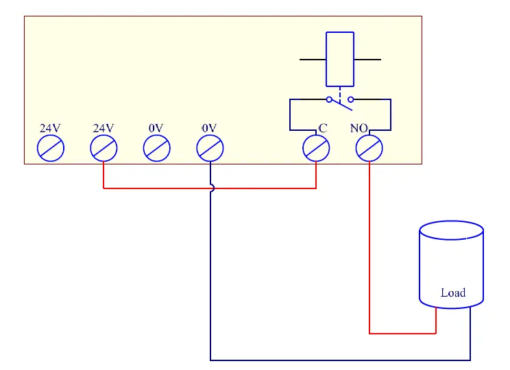
Schematic outline example of how the 24V supply output, together with a relay output, can be used to control a load.
Inclusion/Exclusion
On factory default the device does not belong to any Z-Wave network. The device needs
to be added to an existing wireless network to communicate with the devices of this network.
This process is called Inclusion.
Devices can also be removed from a network. This process is called Exclusion.
Both processes are initiated by the primary controller of the Z-Wave network. This
controller is turned into exclusion respective inclusion mode. Inclusion and Exclusion is
then performed doing a special manual action right on the device.
Inclusion
Press the INCLUSION button once on the device.
Exclusion
Press the INCLUSION button once on the device.
Quick trouble shooting
Here are a few hints for network installation if things dont work as expected.
- Make sure a device is in factory reset state before including. In doubt exclude before include.
- If inclusion still fails, check if both devices use the same frequency.
- Remove all dead devices from associations. Otherwise you will see severe delays.
- Never use sleeping battery devices without a central controller.
- Dont poll FLIRS devices.
- Make sure to have enough mains powered device to benefit from the meshing
Association – one device controls an other device
Z-Wave devices control other Z-Wave devices. The relationship between one device
controlling another device is called association. In order to control a different
device, the controlling device needs to maintain a list of devices that will receive
controlling commands. These lists are called association groups and they are always
related to certain events (e.g. button pressed, sensor triggers, …). In case
the event happens all devices stored in the respective association group will
receive the same wireless command wireless command, typically a ‘Basic Set’ Command.
Association Groups:
Group NumberMaximum NodesDescription
| 1 | 5 | Lifeline.- Reset notification- Basic Report On / Off- Multilevel Sensor Report |
| 2 | 5 | Sends Multilevel Sensor Reports for input 1. |
| 3 | 5 | Sends Multilevel Sensor Reports for input 2. |
| 4 | 5 | Sends Multilevel Sensor Reports for input 3. |
| 5 | 5 | Sends Multilevel Sensor Reports for input 4. |
Configuration Parameters
Z-Wave products are supposed to work out of the box after inclusion, however
certain configuration can adapt the function better to user needs or unlock further
enhanced features.
IMPORTANT: Controllers may only allow configuring
signed values. In order to set values in the range 128 … 255 the value sent in
the application shall be the desired value minus 256. For example: To set a
parameter to 200 it may be needed to set a value of 200 minus 256 = minus 56.
In case of a two byte value the same logic applies: Values greater than 32768 may
needed to be given as negative values too.
Parameter 1: Status LED
Configuration of the status LED.
Size: 1 Byte, Default Value: 1
SettingDescription
| 0 | LED turned off |
| 1 | LED turned on. (Default) |
| 2 | LED flashing at 1 second intervals (0.5 Hz). |
| 3 | LED flashing at 0.5 second interval (1 Hz). |
Parameter 2: Status LED brightness level
Configure the percentage of light in the status LED, when the LED is turned on.
Size: 1 Byte, Default Value: 50
SettingDescription
| 0 – 100 | Specifies the brightness level of the LED when it is on. Default is 50. |
Parameter 3: Thermistor type connected to input 1
This parameter decides which kind of thermistor that is connected to the input.
Size: 1 Byte, Default Value: 1
SettingDescription
| 0 | No thermistor, input is disabled. |
| 1 | 10K NTC. (PART NUMBER: TT02-10KC3-93D-3000R-TPH). (Default) |
Parameter 4: Thermistor type connected to input 2
This parameter decides which kind of thermistor that is connected to the input.
Size: 1 Byte, Default Value: 1
SettingDescription
| 0 | No thermistor, input is disabled. |
| 1 | 10K NTC. (PART NUMBER: TT02-10KC3-93D-3000R-TPH). (Default) |
Parameter 5: Thermistor type connected to input 3.
This parameter decides which kind of thermistor that is connected to the input.
Size: 1 Byte, Default Value: 1
SettingDescription
| 0 | No thermistor, input is disabled. |
| 1 | 10K NTC. (PART NUMBER: TT02-10KC3-93D-3000R-TPH). (Default) |
Parameter 6: Thermistor type connected to input 4
This parameter decides which kind of thermistor that is connected to the input.
Size: 1 Byte, Default Value: 1
SettingDescription
| 0 | 10K NTC. (PART NUMBER: TT02-10KC3-93D-3000R-TPH). (Default) |
| 1 | 10K NTC. (PART NUMBER: TT02-10KC3-93D-3000R-TPH). (Default) |
Parameter 7: Input 1 calibration
Configures the functionality of input 1.
Size: 1 Byte, Default Value: 0
SettingDescription
| -40 – 40 | -4.0 degrees C4.0 degrees C. Default is 0 (0.0 degrees C). |
Parameter 8: Input 2 calibration
Configures the functionality of input 2.
Size: 1 Byte, Default Value: 0
SettingDescription
| -40 – 40 | -4.0 degrees C4.0 degrees C. Default is 0 (0.0 degrees C). |
Parameter 9: Input 3 calibration
Configures the functionality of input 3.
Size: 1 Byte, Default Value: 0
SettingDescription
| -40 – 40 | -4.0 degrees C4.0 degrees C. Default is 0 (0.0 degrees C). |
Parameter 10: Input 4 calibration.
Configures the functionality of input 4.
Size: 1 Byte, Default Value: 0
SettingDescription
| -40 – 40 | -4.0 degrees C4.0 degrees C. Default is 0 (0.0 degrees C). |
Parameter 11: Input 1 report interval
Time interval between consecutive temperature reports. Temperature reports can be also sent as a result of polling.
Size: 2 Byte, Default Value: 6
SettingDescription
| 0 | Reporting of temperatures disabled. |
| 1 – 8640 | Multiply with 10 seconds, 10 seconds24 hours. Default is 6 (60 seconds). |
Parameter 12: Input 2 report interval
Time interval between consecutive temperature reports. Temperature reports can be also sent as a result of polling.
Size: 2 Byte, Default Value: 6
SettingDescription
| 0 | Reporting of temperatures disabled. |
| 1 – 8640 | Multiply with 10 seconds, 10 seconds24 hours. Default is 6 (60 seconds). |
Parameter 13: Input 3 report interval
Time interval between consecutive temperature reports. Temperature reports can be also sent as a result of polling.
Size: 2 Byte, Default Value: 6
SettingDescription
| 0 | Reporting of temperatures disabled. |
| 1 – 8640 | Multiply with 10 seconds, 10 seconds24 hours. Default is 6 (60 seconds). |
Parameter 14: Input 4 report interval
Time interval between consecutive temperature reports. Temperature reports can be also sent as a result of polling.
Size: 2 Byte, Default Value: 6
SettingDescription
| 0 | Reporting of temperatures disabled. |
| 1 – 8640 | Multiply with 10 seconds, 10 seconds24 hours. Default is 6 (60 seconds). |
Technical Data
| Dimensions | 16 x 58 x 86 mm |
| Weight | 320 gr |
| Hardware Platform | ZM5101 |
| EAN | 7071236014065 |
| IP Class | IP 20 |
| Voltage | 230V |
| Load | 5A |
| Device Type | Valve |
| Network Operation | Always On Slave |
| Z-Wave Version | 6.71.03 |
| Certification ID | ZC10-19036400 |
| Z-Wave Product Id | 0x019B.0x0003.0x020A |
| Firmware Updatable | Updatable by Consumer by RF |
| Loads Controlled | 10 |
| Supported Notification Types | |
| Electric Load Type | Dimmable ELV (Magnetic)Dimmable FluorescentDimmable LEDDimmable MLV (Magnetic)ELV (Electronic)FluorescentIncandescentInductive (e.g. Motor)LEDMLV (Magnetic) |
| Sensors | Air Temperature |
| Frequency | Europe – 868,4 Mhz |
| Maximum transmission power | 5 mW |
Supported Command Classes
- Association Grp Info
- Association V2
- Basic V2
- Battery
- Configuration V3
- Device Reset Locally
- Firmware Update Md V4
- Manufacturer Specific V2
- Multi Channel Association V3
- Multi Channel V4
- Powerlevel
- Security
- Security 2
- Sensor Multilevel V5
- Supervision
- Switch Binary
- Transport Service V2
- Version V3
- Zwaveplus Info V2
Explanation of Z-Wave specific terms
- Controller — is a Z-Wave device with capabilities to manage the network.
Controllers are typically Gateways,Remote Controls or battery operated wall controllers. - Slave — is a Z-Wave device without capabilities to manage the network.
Slaves can be sensors, actuators and even remote controls. - Primary Controller — is the central organizer of the network. It must be
a controller. There can be only one primary controller in a Z-Wave network. - Inclusion — is the process of adding new Z-Wave devices into a network.
- Exclusion — is the process of removing Z-Wave devices from the network.
- Association — is a control relationship between a controlling device and
a controlled device. - Wakeup Notification — is a special wireless message issued by a Z-Wave
device to announces that is able to communicate. - Node Information Frame — is a special wireless message issued by a
Z-Wave device to announce its capabilities and functions.
 Z-temp2 Heae4512666 Manual")
 Heatit Z-trm3 Heae5430599 Manual")
 Heatit Z-trm2fx Heae5430555 Manual")
 Z-dim Heae1444444 Manual")
 Z-din 616 Heae4512561 Manual")
 Heatit Z-wave Thermostat Heae5430499 Manual")

 Heatit Z-push Button 2 Heae4512580 Manual")
 Heatit Z-push Button 2 Heae4512680 Manual")
 Heatit Z-push Button 8 Heae4512681 Manual")
 Heatit Z-push Button 4 Heae4512682 Manual")
 Heatit Z-push Button 4 Heae4512683 Manual")
 Heatit Z-push Button 8 Heae4512581 Manual")
 Heatit Z-repeater Heae4512686 Manual")


