aerofabb VW-MK8-GTI-FWD-SE Thread Galling Installation Guide
WARNING
We provide Fasteners in Stainless Steel to ensure a long life span. Although Stainless Steel has many benefits like extreme corrosion resistance, threads can be sensitive to Nylon Lock Nuts. We recommend installing hardware with an Anti Seize thread lubricant to prevent thread galling. Slowing down speed of install and keeping bolts stationary while tightening nuts are common practices to prevent thread galling.
OVER VIEW
NOTES:
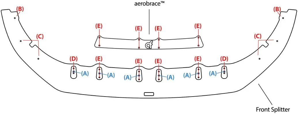
- Labeled Hardware corresponds to labeled holes shown in diagram.
- Outer spacers (labeled as ID in Hole Identification Diagram) are packaged separately from Inner Spacers (labeled as E in Hole Identification Diagram). Mounting spread differs from one another.
HARDWARE (A)
| QTY | DESCRIPTION |
| 6 | M4 X 8MM BOLT |
ALIGNMENT HARDWARE (B)
| QTY | DESCRIPTION |
| 2 | 8/32 CLIP-ON NUT |
| 2 | 8/32 X 1 1/4″ BOLT |
| 2 | #8 X 3/4″ OD WASHER |
HARDWARE (C)
| QTY | DESCRIPTION |
| 4 | M6 X 18MM BOLT |
| 4 | FENDER WASHER |
| 4 | 18MM WASHER |
| 4 | M6 NYLON LOCKNUT |
HARDWARE (D)
| QTY | DESCRIPTION |
| 4 | M6 X 30MM BOLT |
| 8 | FENDER WASHER |
| 4 | M6 NYLON LOCKNUT |
HARDWARE (E)
| QTY | DESCRIPTION |
| 4 | M6 X 30MM BOLT |
| 8 | FENDER WASHER |
| 4 | M6 NYLON LOCKNUT |
NOTES:
- CONFIRM NO HARDWARE IS MISSING BEFORE INSTALL.
- Outer spacers (labeled as in Hole Identification Diagram) are packaged separately from Inner Spacers (labeled as – in Hole Identification Diagram). Mounting spread differs from one another.
MAKE THE FOLLOWING TOOLS READY FOR USE
- Drill
- 14″ Drill Bit
- 10mm Wrench
- 3/32″ Hex Wrench
- 4mm Hex Wrench
- 2.5mm Hex Wrench
- T-25 Torx
- Anti-Seize (recommended)
aerofabb, LLC is not responsible for damage to you or your vehicle while following this Install Guide and/or installing aerofabb products. Professional install is recommended. aerofabb also recommends installing hardware with Anti-Seize (thread lubricant) and Hand Tools to prevent thread galling.
- Safely raise vehicle in the air allowing you to gain easy access to the underside of Bumper.
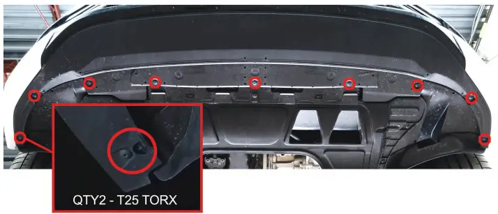
- Using a T-25 Torx, identify and remove the 11 factory Splash Pan Torx screws on underside of Bumper as shown below.

- Using a T-25 Torx, identify and remove the 6 lower Fender Liner Torx screws. (3 in each Wheel Well on Bumper Side)
- Pull away Fender Liner from Bumper. Identify and remove the factory Clip On Nuts.
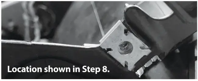
- Replace the factory Clip-On Nuts with the 8-32 Clip-On Nuts provided in ALIGNMENT HARDWARE (B). Push until the Clips-On Nuts snap into place.

- Using a 2.5mm Hex Wrench and HARDWARE (A) , assemble your Front Splitter by installing the 6 Spacer Pucks and tighten as shown below.
Note: Outer spacers (labeled as D in Hole Identification Diagram) are packaged separately from Inner Spacers (labeled as E in Hole Identification Diagram). Mounting spread differs from one another.
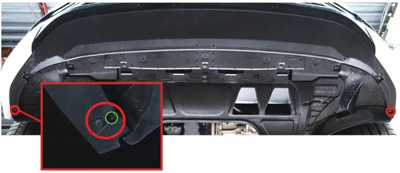
- Raise your aerofabb Front Splitter to bumper lining up Splitter holes with Bumper holes circled in geen below (inner holes). (these holes will line up with your 8-32 Clip-On Nuts)

- Using a 3/32″ Hex Wrench, install the remaining hardware from ALIGNMENT HARDWARE (B). Fasten Splitter to Bumper by passing through Splitter holes (B) and tighten.
- Hold Splitter flat against the bottom of the Bumper. Use a 1/4″ Drill Bit to drill through the 4 Splitter holes and into the Bumper.

NOTES:
- Do Not Over Tighten Hardware.
- Support weight of Splitter between steps 9-11 being sure not to let it hang until Hardware C is in place.
- Run Drill Bit through multiple passes to ensure hole is clear of debris.
- Be sure Drill Bit is not angled while drilling.
Using a 4mm Hex Wrench and 10mm Wrench, install HARDWARE (C) through holes (C) and tighten. (Pull Splash Pan down to gain access to backside)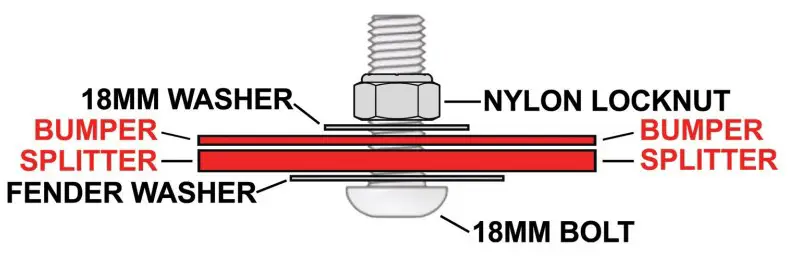
Use a 1/4″ Drill Bit to drill through the 4 Splitter holes (D) and into the Bumper.
Using a 4mm Hex Wrench and 10mm Wrench, install HARDWARE (D) through holes (D) and tighten. (Pull Splash Pan down to gain access to backside)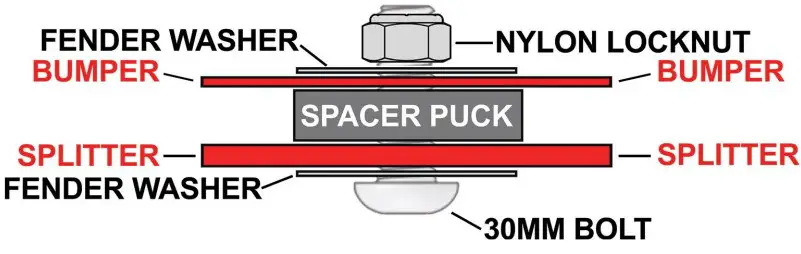
Use a 1/4″ Drill Bit to drill through the 8 remaining Splitter holes (E) and
into the Bumper.
Using a 4mm Hex Wrench and 10mm Wrench, install HARDWARE (E) through holes (E) and tighten.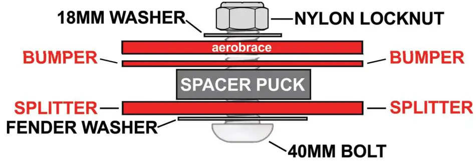
aerobrace installs on topside of bumper followed by 18mm washer and locknut.
Using a T-25 Torx, Reinstall the factory Splash Pan/Fender Liner Torx screws.
Check all hardware for tightness.
This completes the installation. You will be left with 2 factory T-25 Torx Screws and 2 factory Clip-On Nuts.
NOTES:
- Do Not Over Tighten Hardware.
- Run Drill Bit through multiple passes to ensure hole is clear of debris.
- Be sure Drill Bit is not angled while drilling.