
![]()
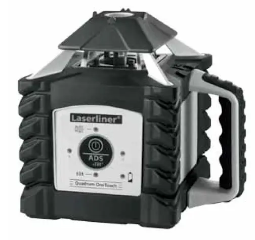
Laserliner 053 200 Quadrum OneTouch Rotary Laser
Read the operating instructions and the enclosed brochure “Guarantee and additional notices” completely. Follow the instructions they contain. This document must be kept in a safe place and if the laser device is passed on, this document must be pased on with it.
Fully automatic rotary laser
- Laser modes: spot, scan, rotary and hand receiver mode
- All functions can be controlled remotely.
- optional SensoLite 410: Laser receiver range up to 400 m radius
- optional SensoMaster 400: Laser receiver range up to 400 m radius.
With longer laser receiver unit and millimetre exact distance reading for laser level.
General safety instructions
- The device must only be used in accordance with its intended purpose and within the scope of the specifications.

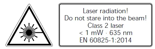
- Attention: Do not look into the direct or reflected beam. – Do not point the laser beam towards persons.
- If a person’s eyes are exposed to class 2 laser radiation, they should shut their eyes and immediately move away from the beam
- Under no circumstances should optical instruments (magnifying glass, microscope, binoculars) be used to look at the laser beam or reflections.
- Do not use the laser at eye level (1.40 … 1.90 m)
- Reflective, specular or shiny surfaces must be covered whilst laser devices are in operation.
- In public areas shield off the laser beam with barriers and partitions wherever possible and identify the laser area with warning signs. Tampering with (making changes to) the laser device is not permitted.
- This device is not a toy – keep out of the reach of children.
Special product features and functions
 The rotary laser starts up by rotating and aligning itself automatically. It is set to the required initial position (to within an operating angle of +5°) and the automatic system then performs the necessary fine adjustment, with two electronic measurement sensors detecting the X and Y axes.
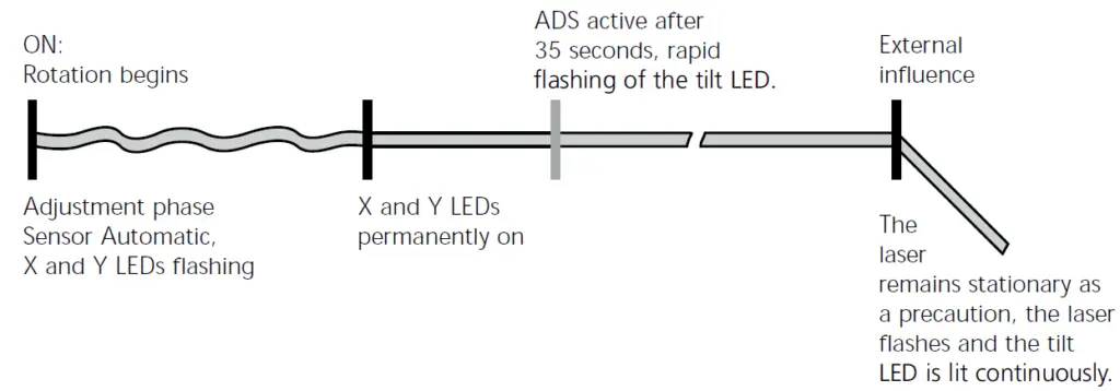
 The anti-drift system (ADS) prevents erroneous or inaccurate measurements. How it works: The laser automatically switches to active ADS mode 35 seconds after being switched on and is permanently checked to ensure it is aligned correctly. If the device moves due to the influence of external factors or the laser lose its height reference, the laser will come to a standstill. Additionally, the laser flashes, and the tilt LED is lit continuously. To continue working switch the device off and on again. Erroneous and inaccurate measurements are thus prevented simply and reliably.
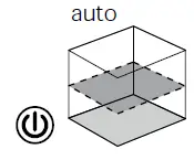
 ADS is automatically activated after the device is switched on in order to prevent changes in position caused by external influences affecting the set-up device. The tilt LED flashes to indicate that the ADS function is active; see the diagram below. Press the ON/OFF button for 3 seconds to switch off the ADS function.
Note: The ADS does not activate the monitoring function until 35 seconds after the laser levelling procedure has been completed (set-up phase). The tilt, X and Y LEDs flash during the set-up phase; the tilt LED flashes rapidly and the X and Y LEDs are permanently on when ADS is active.
ADS function
Transport LOCK: The device is protected by a special motor brake during transport.
The device characterised by specific protection against dustand rain.
Space grids: These show the laser planes and functions.
auto: Automatic alignment/ man: Manual alignment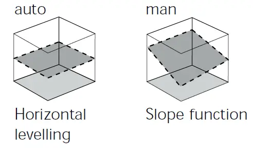
Battery charging
- Charge the device’s battery completely prior to use.
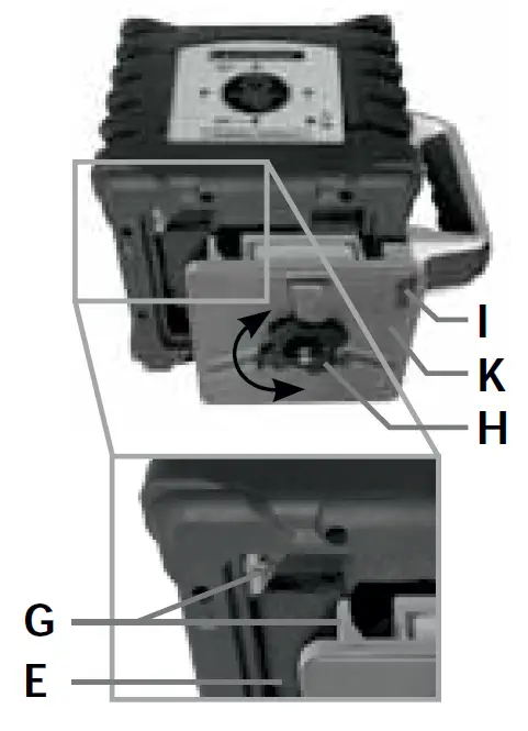
- Connect the charger to main power supply and the charging socket () of the battery compartment (K). Please only use the charger supplied; using a different charger will invalidate the warranty. The rechargeable battery can also be charged when it is not inserted in the device.
- When the rechargeable battery is being charged, the LED on the charger (M) lights up red. When the LED changes to green, charging is complete. When the unit is not connected to the charger the power charger’s LED lamp will blink (M).

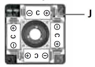
- Alkaline batteries (4 x type C) can be used as an alternative. Insert them in the battery com- partment (0) as per the installation symbols. – Insert battery (K)/ battery compartment (0) into slot (E) and secure it in place with tastening screw (H). The electrical contacts (G) must be Connected.
- With the rechargeable battery inserted, the device is ready to run even during charging.
- When all 4 LEDs (2, 4, 5, 6) light up briefly and the device switches off, the batteries must be replaced or the rechargeable battery charged.

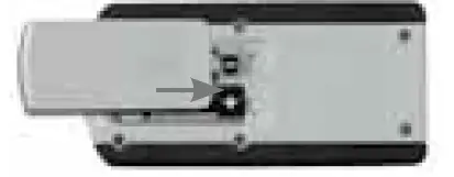
Insert batteries into the remote control
- Observing the correct polarity.


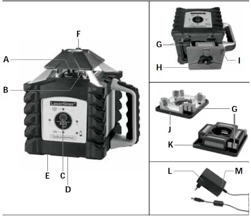
A Prism head/laser beam outlet
B Receiver diodes for remote
Control (4 x)
C Control panel (ON/OFF button)
D 5/8″ thread (bottom)
E Slot for rechargeable battery
battery compartment
F Fast focus
G Electrical contacts
H Battery compartment / battery fastening nut
I Charging socket
J Battery compartment
K Rechargeable Battery Compartment
L Mains unit/charger
M Operation indicator
red: the battery is charging
green: charging process complete
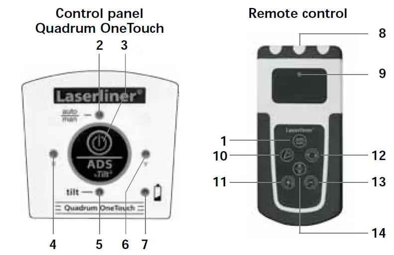
- auto/man function
- auto/man function LED
LED off: automatic alignment
LED on: manual alignment - ON/OFF button
- X-axis LED
- Tilt function LED
- Y axis LED
- Battery display
- Infrared signal emitter
- Operation indicator
- Scan mode
- Positioning button (rotate to the right)
auto/man. function:
Incline X/Y axes - Rotary speed for selection
600/300/ 120/60/0 rpm - Positioning button
(rotate to the left)
auto/man. function:
Incline X/Y axes - X/Y axis switch-over
Horizontal leveling
- Horizontal: Position the device on a level surface or on a tripod.
- Press the “ON/OFF” switch

Note: auto/man function LED OFF: Automatic alignment
- The device levels itself automatically to within a range of +5°. The laser rotates and the tilt, X and Y LEDs flash during the set-up phase. When levelling is complete, the tilt LED flashes rapidly and the X and Y LEDs are permanently on. The laser rotates at maximum speed. Refer also to the sections about “Sensor Automatic” and “ADS Tilt”.
Note: If the device has been placed on a surface with too much of a slope (more than 5°), the prism head remains stationary and the laser starts to tlash. The device must then be placed on a more even surface.
Slope function up to 5° – horizontal
This function deactivates the automatic sensor. To use the function, press the auto/man button. The plus/minus buttons are used to re-adjust the slope by means of a motor. In the process, the X-and Y-axis can be adjust separately. Refer to the illustrations below.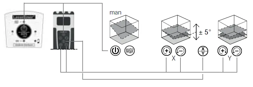
Slope function > 5°
Steeper slopes can be set using the angle plate, which is available as an optional extra (product ref. 080.75). TIP: Allow the device to align itself automatically and set the angle plate to the zeroo position. Then press the auto/man button to switch the automatic sensor off. Finally, incline the device to the angle you require.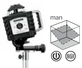
Note: auto/man function LED ON: Manual alignment
Laser modes
Rotary mode
The following speeds can be set using the rotary button: 0, 60, 120, 300, 600 rpm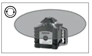
Spot mode
You access spot mode by pressing the rotary button repeatedly until the laser stops rotating The laser can then be positioned exactly at the measuring point by means of the direction buttons.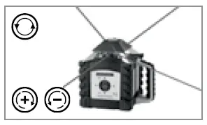
Scan mode
The scan button can be used to activate and set a light-intensive segment in 4 different widths. You position the segment via the direction buttons.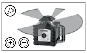
Hand receiver mode
Working with the laser receiver (available as an optional extra): Set the rotary laser to maximum speed and switch on the laser receiver. Refer to the operating instructions for the respective laser receiver about this.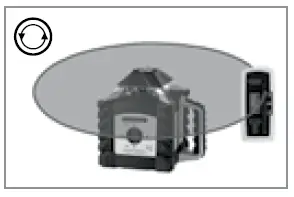
Technical data
| Technical data (2TAIDBS SN SDBGMHB@K @KSDQ@SHNMR. 07.16) | |
| Self-levelling range | ± 5° |
| Accurancy | ± 0.75 LL / 10 L |
| Horizontal levelling | Automatic with electronic sensors and servo motors |
| Self-levelling alignment time | OOQNW. 35 RDBNMCR NUDQ SGD entire operating angle |
| Rotation speed | 0, 60, 120, 300, 600 RPM |
| Remote control | Infrared IR |
| Laser wavelengths | 635 nm |
| Laser class | 2 ($-60825-1:2014) |
| Laser output rating | < 1 mW |
| Power supply | High-performance rechargeable A@SSDQX / A@SSDQHDR (4 W SXOD “) |
| Rechargeable battery life | @OOQNW. 35 G |
| Non-rechargeable battery life | @OOQNW. 50 G |
| Battery recharging time | B@. 7 G |
| Operating temperature | -10” … + 50” |
| Storage temperature | -10” … + 70” |
| Protection class | IP 66 |
| #HLDMRHNMR (6 W ‘ W #) / 6DHFGS (HMBK. A@SSDQHDR) | 215 x 205 x 165 mm / 2.6 JF |
| Remote control | |
| Power supply | 2 x type AAA |
| Remote control range | L@W. 30 L ((1-“NMSQNK) |
| 6DHFGS (HMBK. A@SSDQX) | 0.07 kg |
EU directives and disposal
This device complies with all necessary standards for the free movement of goods within the EU.
This product is an electric device and must be collected
separately for disposal according to the European Directive on waste electrical and electronic equipment.
Further safety and supplementary notices at: www.laserliner.com/info
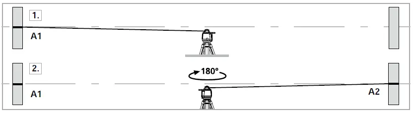
Preparing the calibration check
It is possible for you to check the calibration of the laser. To do this, position the device midway between 2 walls, which must be at least 5 metres apart. Switch the device on. The best calibration results are achieved if the device is mounted on a tripod. IMPORTANT: The automatic sensor must be active (auto/man. LED is off).
- Mark point A1 on the wall.
- Turn the device through 180° and mark point A2. You now have a horizontal reference between points A1 and A2.

Performing the calibration check - Position the device as near as possible to the wall at the height of point
A1. Now adjust the device in the X axis. - Turn the device through 180° and mark point A3. The difference between points A2 and A3 is the tolerance for the X axis.
- To check the Y axis, repeat steps 3 and 4

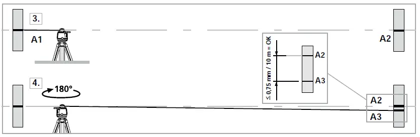
Note: lf points A2 and A3 are more than 0.75 mm / 10 m apart on either the X or Y axis, the device is in need of adjustment. Contact your authorised dealer or else the UMAREX-LASER LINER Service Department.
Adjustment mode
Take the alignment of the rotary laser into account when performing adjustment work. Always adjust all the axes.
X-axis adjustment
Activate adjustment mode: Switch on the Quadrum OneTouch.
Simultaneously press the auto/man button and the X/Y button until the X LED flashes rapidly.
Adjustment: Use the plus/minus buttons to move the laser from its current position to the height of reference point A2.
Cancel adjustment: Switch the device off.![]()
Save: Simultaneously press the auto/man button and the XY button until the X LED lights up.
Y axis adjustment
Activate adjustment mode: Switch on the Quadrum One Touch.
Simultaneously press the auto/man button and the X/Y button until the X LED flashes rapidly.
Switch to the Y axis using the XY button.![]()
Adjustment: Use the plus/minus buttons to move the laser from its Current position to the height of reference point A2. Cancel adjustment: Switch the device off.
Save: Simultaneously press the auto/man button and the XY button until the Y LED lights up.
Note: Regularly check the adjustment before use, after transport, and after extended periods of storage. Always make sure to control all axes.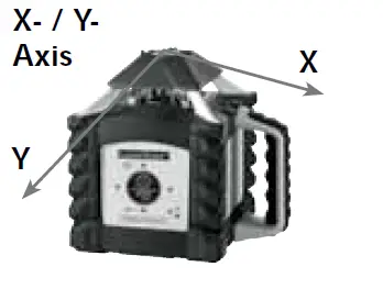
Umarex GmbH & Co. KG
– Laserliner –
Möhnestraße 149, 59755 Arnsberg, Germany
Tel.: +49 2932 638-300, Fax: +49 2932 638-333
[email protected]
Umarex GmbH & Co. KG
Donnerfeld 2
59757 Arnsberg, Germany
Tel.: +49 2932 638-300, Fax: -333
www.laserliner.com


