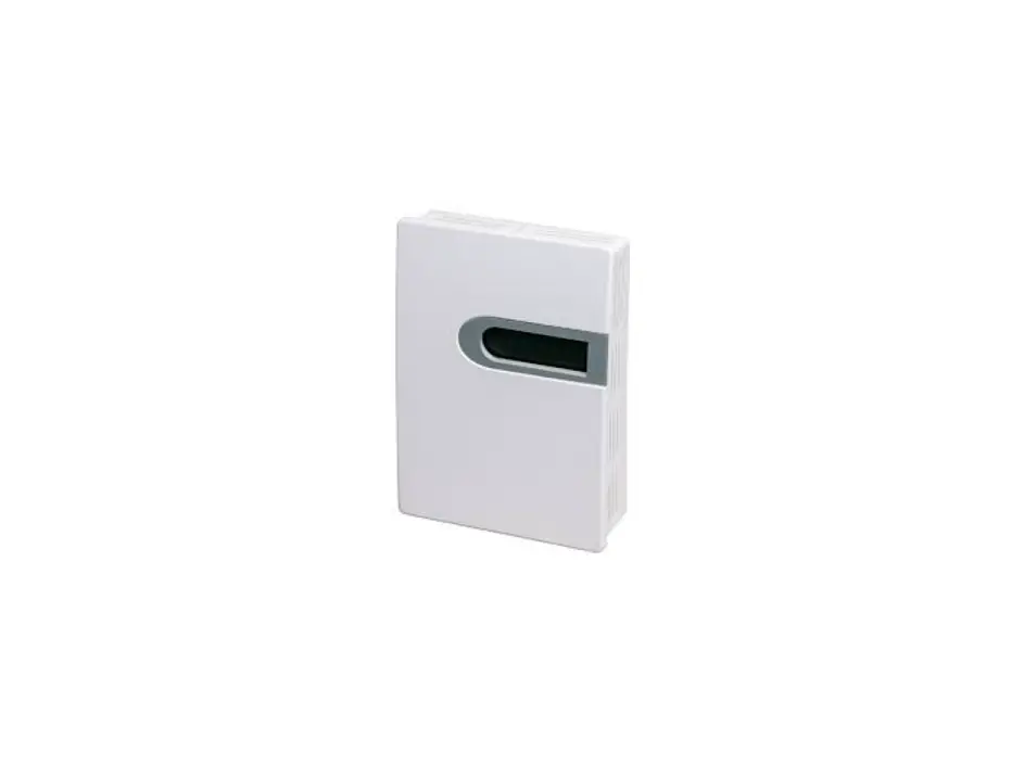
ACI VOC-ROOM Room Mount Instruction Manual

GENERAL INFORMATION
VOCs are emitted as gases from certain solids or liquids, such as building materials and furnishings, office equipment, cleaners and disinfectants, etc. These types of contaminants directly affect indoor air quality and occupant comfort. Measuring and communicating VOC levels back to the BAS will help users adjust ventilation to maintain proper IAQ levels.
These units utilize a high-performance metal oxide sensor and will output TVOC levels in a range from 0-1000 ppb. All units come equipped with both analog and RS485 Modbus RTU outputs easily interface into existing BAS systems.
IMPORTANT PRECAUTIONS
Read the following instructions carefully before using the indoor air quality sensor described in this document to avoid erroneous readings and to prevent the device from permanent damage.
- The sensor must not be exposed to high concentrations of organic solvents, ammonia, silicone vapour or cigarettesmoke in order to avoid poisoning the sensitive layer.
MOUNTING INSTRUCTIONS
For optimal temperature readings, follow these tips:
- Do not install on external walls.
- Avoid air registers, diffusers, vents, and windows
- Avoid confined areas such as shelves, closed cabinets, closets, and behind curtains.
- Eliminate and seal all wall and conduit penetrations. Air migration from wall cavities may alter temperature readings.
- Do not install near heat sources. eg: lamps, radiators, direct sunlight, copiers, chimney walls, walls concealing hot-water pipes
FIGURE 1: ENCLOSURE DIMENSIONS
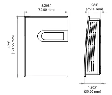
FIGURE 2: OPENING COVER
Separate the cover from the base by inserting a flat head screwdriver into the top slot marked “OPEN”. Pry the cover forward.
Attach the base directly to the wall or to a standard 2″x4″junction box using (2) #6-32 x 1″ screws.
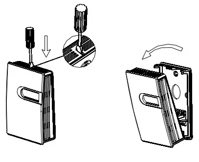
FIGURE 3: BACKPLATE
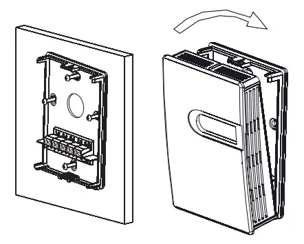
Refer to the wiring instructions to make necessary connections. After wiring, attach the cover to the base by snapping the top of the cover on first and then the bottom.
Take care when mounting. Check local code for mounting height requirements. Typical mounting heights are 48-60”(1.22-1.52m) off the ground and at least 1.5’(0.5m) from the adjacent wall. The sensor should be mounted in an area where air circulation is well mixed, and not blocked by obstructions.
WIRING INSTRUCTIONS PRECAUTIONS DO NOT RUN THE WIRING IN ANY CONDUIT WITH LINE VOLTAGE (24/120/230VAC).
- Remove power before wiring. Never connect or disconnect wiring with power applied.
- It is recommended that you use an isolated UL-listed Class 2 transformer when powering the unit with 24 VAC. Failure to wire the devices with the correct polarity when sharing transformers may result in damage to any device powered by the shared transformer.
- IF THE 24 VDC OR 24VAC POWER IS SHARED WITH DEVICES THAT HAVE COILS SUCH AS RELAYS, SOLENOIDS, OR OTHER INDUCTORS, EACH COIL MUST HAVE AN MOV, DC/AC
TRANSORB, TRANSIENT VOLTAGE SUPPRESSOR (ACI PART: 142583), OR DIODE PLACED ACROSS THE COIL OR INDUCTOR. THE CATHODE, OR BANDED SIDE OF THE DC TRANSORB OR DIODE, CONNECTS TO THE POSITIVE SIDE
ACI recommends 16 to 26 AWG twisted pair wires or shielded cable for all transmitters.
ACI recommends using BELDEN 3105 for communication(Modbus) wiring. This wire has 120 ohm input impendence. The terminal blocks allow for (1) or (2) wires to be connected in each position for daisy chaining. Daisy chain the RS- 485 wiring and do not use “Star” or “T” wiring. Avoid running communication wires next to AC line voltage wires. These can be sources of noise that can affect signal quality.
FIGURE 4: WIRING
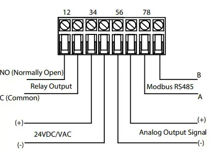
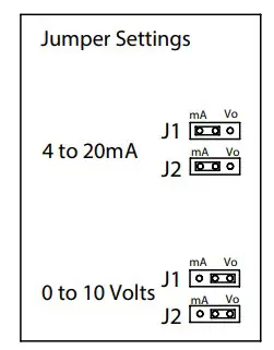
FIGURE 5: JUMPERS SETTINGS
RELAY SET POINT SELECTION
The relay set point can be changed by the jumper selections shown below(Fig 6).
The default mode is Balance (220 ppb).
FIGURE 6: RELAY SET POINT SELECTION

| MODE | RELAY SET POINT |
| Energy Saving (1) | 280 ppb |
| Balance (Default)(2) | 220 ppb |
| Quality (3) | 160 ppb |
SYSTEM ERROR SIGNAL
| Error Code | Possible Problems | Solution |
| Er3 |
Sensor detection failure | Check the electrical connection or return to factory |
| Transmitter output is 110% of full range | ||
| Three colors flash in turns |
DEVICE CONFIGURATION THROUGH MODBUS RTU MODBUS RTU INTERFACE
The Modbus Remote Terminal Unit (RTU) data link protocol uses EIA-485 as a two-wire, daisy chain network. A branch is a discrete chain of devices connected to a controller. The max number of devices per segment is (32), as per the Modbus specifications. 4000 ft (1219.2 m) is the maximum recommended length for a segment, which includes all devices from the controller to the last device in the daisy chain.
Each branch must have all devices connected with (A) connected to (A) and (B) connected to (B). If a shielded cable is used, this is not to be connected to the devices. The shield cable should only be connected on one end to earth ground, usually at the controller.
Each device must be configured for the correct baud rate and have a unique address in each branch. The baud rate for the branch is set by the controller.
EOL TERMINATION RESISTANCE SELECTION
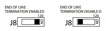
RS-485 requires that the last device in a chain have a termination resistor. This is controlled using the J8 switch as shown in FIGURE 7. When the jumper is set to ON(Enabled), a 120 Ohm resistance is added in parallel to the data line. When the jumper is set to the left(Disabled), the resistance is not added. By default, the jumper is placed in the disabled position.
FIGURE 7: EOL TERMINATION
A typical Modbus RTU mode message frame is shown below. In the Modbus RTU mode, the messages between frames are separated by at least 3.5 characters time’s silent interval. If the silent interval
between two characters is more than 3.5 characters time, the former character was transferred successfully, and the current character’s transmission starts.
MODBUS MESSAGE

ADDRESS SELECTION
A typical Modbus RTU mode message frame is shown below. In the Modbus RTU mode, the messages between frames are separated by at least 3.5 characters time’s silent interval. If the silent interval between two characters is more than
3.5 characters time, the former character was transferred successfully, and the current character’s transmission starts.
BAUD RATE, DATA BITS, PARITY, AND STOP BITS SELECTION
Baud rate is set to 9600, but can also be configured to 4800 via the register.
The device that requests information is called the Modbus Master and the devices giving the information are Modbus Slaves. The Modbus sensors are slave devices and the number of Data Bits needs to be the same as in the Master device configuration. ACI’s Modbus RTU sensors utilize 8 data bits during communication exchange.
Parity default setting is NONE. Stop bit default setting is 1. Both settings can adjusted via the register.
FUNCTION
The function code is the second data in the frame. Valid function codes are from 0~127 (01H~7FH). See the relevant Modbus standard. It supports 03H/06H function codes, shown as the following Modbus Poll software. The detail register addresses are in: 6 General registers table.
BROADCAST MODE TO WRITE DATA TO SLAVE
Using broadcast mode, customer can write data to all slaves connected to the network. Address of broadcast mode to write data is 0.
For example: change slave address with broadcast mode, customer can set a new slave address. Note: since this operation will modify all the addresses of the slavers to the same address, it is NOT applicable for network of more than one slave.
SPECIAL MODE TO READE DATA FROM SLAVE
With the special mode, customer can read the register data under the circumstance of NOT knowing the slave address. Address of special mode read data: 255(0xFF)
Note: this operation is applicable for ONLY ONE slave in the network.
MODBUS RTU MAP
| Register Address | R/W | Type | Definition | Remarks |
| 40001, 00000 | R | Signed | Product code | Product code |
| 40002, 00001 | R | Signed | Equivalent CO2 value | equivalent CO2 value, Unit: ppm VOC measured value, Unit: ppb |
| 40003, 00002 | R | Signed | VOC measured value | |
| 40004, 00003 | R | Signed | Reserved | |
| 40005, 00004 | R | Signed | Software version | Example: 100 |
| 40006, 00005 | R | Signed | working state | Working state. 0: normal. 0x10: busy. 0x80 error. 0xAA: is not connected. |
| 40007, 00006 | R | Signed | Relay state | 0: Relay is off, 1: Relay is on |
| 40008, 00007 | R | Signed | LED state | 0: Green, 1: Yellow, 2: Red, 0xff: Wrong Alarm. |
| 40009, 00008 | R | Signed | Control state | 0: Energy Saving, 1: Balance, 2: Quality |
| …… | ||||
| 40014, 00013 | R/W | Signed | RS485-Modbus RTU slave address | Default slave address =1, (RTU,9600,8,n,1), Range: 1~255 |
| 40015, 00014 | R/W | Signed | Reserved | |
| 40016, 00015 | R/W | Signed | Function register | Write ( 06 function ) “21485” to return factory setting |
| 40017, 00016 | R/W | Signed | Not Applicable | NA |
| 40018, 00017 | R/W | Signed | Not Applicable | NA |
| 40019, 00018 | R/W | Signed | Not Applicable | NA |
| 40020, 00019 | R/W | Signed | Not Applicable | NA |
| 40021, 00020 | R/W | Signed | Not Applicable | NA |
| …… | ||||
| 40029, 00028 | R/W | Signed | Baud rate | 4800 or 9600 |
| 40030, 00029 | R/W | Signed | Parity | 0: NONE,1: ODD,2: EVEN |
Note: 1. 40001 is PLC mode ADDRESS (BASE 1); 00000 is PROTOCOL ADDRESS (BASE 0).
- Function register 40016 instructions :
Use the 06 function code to write 21845 to the register 40016 and return the factory settings. Use the 06 function code to write 23278 to the register 40016, and save the parameters.
| PRODUCT SPECIFICATIONS | |
| Supply Voltage: | 16-28VAC/16-35VDC (Reverse Polarity Protection) |
| Supply Current: | LCD: 50mA | Non-LCD: 33mA |
| Measurement Range: | 0-1000 ppb TVOC (Isobutene) |
| Output: | 4-20mA(Default), 0-10VDC |
| Output Load Resistance: | 4-20 mA: 500 Ohms maximum | 0-10 VDC: 2K Ohms Minimum |
| Relay: | N.O. rated 3A @ 30VDC, 3A @250VAC |
| Relay Trip Point: | 230ppb |
| Response Time: | <5 seconds |
| Warm Up Time: | 15 minutes |
| Communication Protocol: | Modbus RTU; EIA RS-485 |
| Sensor Addresses: | 1-247 |
| Supported Baud Rates: | 4800 or 9600 |
| Parity: | None/Even/Odd |
| Stop Bits: | 1 |
| Data Bits: | 8 |
| Connections / Wire Size: | Screw Terminal Blocks / 16 AWG (1.31 mm2) to 22 AWG (0.33 mm2) |
| Terminal Block Torque Rating: | 0.45 lbf-in (0.5 Nm) nominal |
| Operating Temperature Range: | 32 to 122°F (0 to 50°C) |
| Storage Temperature Range: | -4 to 140°F (-20 to 60°C) |
| Operating Humidity Range: | 10 to 95% RH, non-condensing |
| Enclosure Protection: | IP30 |
| Enclosure Material / UL Flammability: | ABS Plastic / UL94V-0 |
WARRANTY
The ACI VOC Room Series are covered by ACI’s Two (2) Year Limited Warranty, which is located in the front of ACI’S SENSORS & TRANSMITTERS CATALOG or can be found on ACI’s web site: www.workaci.com.
W.E.E.E. DIRECTIVE
At the end of their useful life the packaging and product should be disposed of via a suitable recycling centre. Do not dispose of with household waste. Do not burn.


