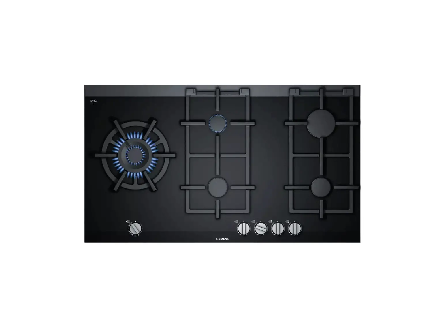
SIEMENS ER9A6SB70 Gas Hob
Installation instructions
| ID | Gas | Nz | Qn (kW) | m3/h | g/h | Z (mm) | M |
| G20/20 mbar | 72 | 1,10 | 0,105 | – | – | B | |
| G20/25 mbar | 65 | 1,10 | 0,105 | – | – | B | |
| G25/20 mbar | 79 | 1,10 | 0,122 | – | – | B | |
| G25/25 mbar | 78 | 1,10 | 0,122 | – | – | B | |
| G25.1/25 mbar | 78 | 1,10 | 0,122 | – | – | B | |
| G25.3/25 mbar | 78 | 1,10 | 0,119 | – | – | B | |
| G30/29 mbar | 53 | 1,10 | – | 80 | – | A | |
| G30/37 mbar | 53 | 1,10 | – | 80 | – | A | |
| G30/50 mbar | 48 | 1,10 | – | 80 | – | A | |
| G31/37 mbar | 53 | 1,10 | – | 79 | – | A | |
| G20/20 mbar | 93 | 1,90 | 0,181 | – | – | B |

| ID | Gas | Nz | Qn (kW) | m3/h | g/h | Z (mm) | M |
| G20/25 mbar | 91 | 1,90 | 0,181 | – | – | B | |
| G25/20 mbar | 105 | 1,90 | 0,211 | – | – | B | |
| G25/25 mbar | 104 | 1,90 | 0,211 | – | – | B | |
| G25.1/25 mbar | 104 | 1,90 | 0,21 | – | – | B | |
| G25.3/25 mbar | 104 | 1,90 | 0,21 | – | – | B | |
| G30/29 mbar | 70 | 1,90 | – | 138 | – | A | |
| G30/37 mbar | 68 | 1,90 | – | 138 | – | A | |
| G30/50 mbar | 60 | 1,90 | – | 138 | – | A | |
| G31/37 mbar | 70 | 1,90 | – | 136 | – | A | |
| G20/20 mbar | 125 | 2,80 | 0,267 | – | – | B | |
| G20/25 mbar | 109 | 2,80 | 0,267 | – | – | B | |
| G25/20 mbar | 141 | 2,80 | 0,31 | – | – | B | |
| G25/25 mbar | 118 | 2,80 | 0,31 | – | – | B | |
| G25.1/25 mbar | 118 | 2,80 | 0,31 | – | – | B | |
| G25.3/25 mbar | 118 | 2,80 | 0,304 | – | – | B | |
| G30/29 mbar | 83 | 2,80 | – | 203 | – | A | |
| G30/37 mbar | 82 | 2,80 | – | 203 | – | A | |
| G30/50 mbar | 74 | 2,80 | – | 203 | – | A | |
| G31/37 mbar | 83 | 2,80 | – | 200 | – | A | |
| G20/20 mbar | 1 – 171 | 6,10 | 0.582 | – | 4 | B | |
| 2 – 69 | |||||||
| G20/25 mbar | 1 – 163 | 6,10 | 0.582 | – | 4 | B | |
| 2 – 62 | |||||||
| G25/20 mbar | 1 – 194 | 6,10 | 0.676 | – | 4 | B | |
| 2 – 76 | |||||||
| G25/25 mbar | 1 – 180 | 6,10 | 0.676 | – | 4 | B | |
| 2 – 72 | |||||||
| G25.1/25 mbar | 1 – 180 | 5,80 | 0.642 | – | 4 | B | |
| 2 – 72 | |||||||
| G25.3/25 mbar | 1 – 180 | 6,10 | 0.661 | – | 4 | B | |
| 2 – 72 | |||||||
| G30/29 mbar | 1 – 115 | 6,10 | – | 442 | 11 | A | |
| 2 – 47 | |||||||
| G30/37 mbar | 1 – 107 | 6,10 | – | 442 | 13 | A | |
| 2 – 44 | |||||||
| G30/50 mbar | 1 – 100 | 6,10 | – | 442 | 5 | A | |
| 2 – 42 | |||||||
| G31/37 mbar | 1 – 115 | 6,10 | – | 442 | 11 | A | |
| 2 – 47 |
Safe installation
Follow these safety instructions when installing the appliance.
- Read this instruction manual carefully.
- The images shown in these instructions are for guidance only.
- The appliance can only be used safely if it is correctly installed according to the safety instructions. The installer is responsible for ensuring that the appliance works perfectly at its installation location.
WARNING Risk of explosion!
Escaping gas may cause an explosion.
- All Installation, connection, regulating and conversion work to a different gas type must be carried out by an authorised professional while taking into account the respective applicable regulations and legal requirements as well as the regulations regarding the local electricity and gas suppliers. Special attention must be paid to the provisions and guidelines that are applicable for the ventilation. For conversion work to a different gas type, we recommend that you call the after-sales service.
- Ensure that the kitchen is sufficiently ventilated, in particular when operating the gas cooking appliance.
- Do not connect the appliance to an exhaust gas system for combustion products.
- Never install the appliance in boats or in vehicles.
- The warranty applies only when using the appliance as intended.
- Before installing the appliance, check that the local conditions of the supplier are compatible with the appliance settings specified on the rating plate (type of gas and pressure, power, voltage).
- Secure the power cord to the cabinet to prevent it from touching hot parts of the oven or hob.
- Before any work is carried out on the appliance, switch off the power supply and the gas supply.
- Connect the appliance to the power supply using the earth.
- Do not make any changes to the inside of the appliance. If required, contact our technical customer service.
Before installing
- This appliance is a class 3 appliance in accordance with the EN 30-1-1 standard for gas appliances: Built-in appliance.
- The unit in which the appliance is installed must be stable and secured appropriately.
- The units in the vicinity of the appliance, the laminated panels and the adhesive with which they are secured must be made of non-flammable, heat resistant materials.
- Do not install this appliance above refrigerators, washing machines, dishwashers or similar.
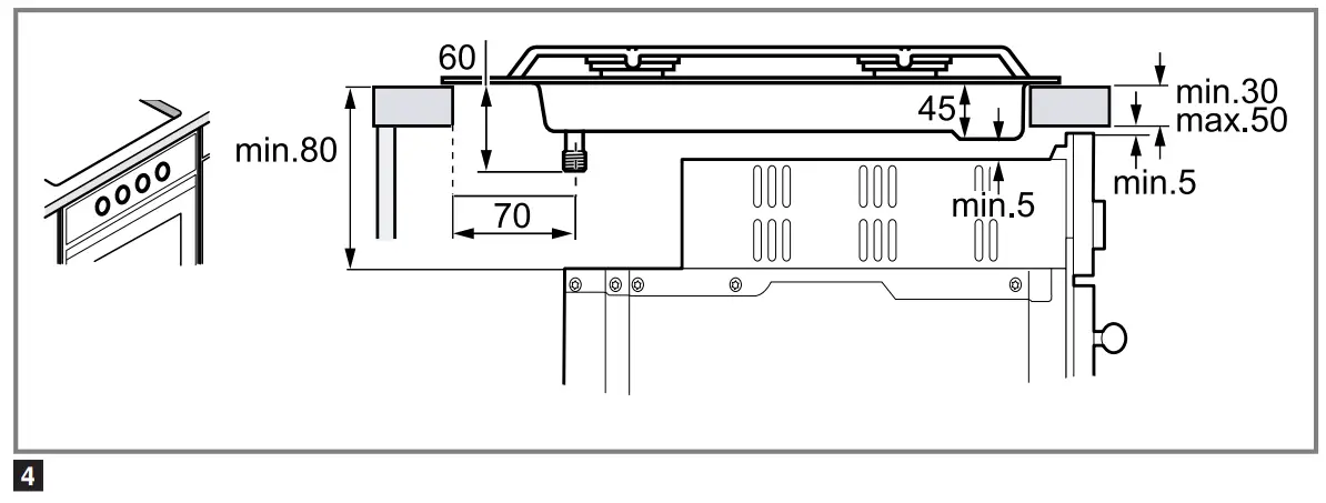
- The appliance must only be installed on an oven with forced ventilation. Check the dimensions of the oven in the installation instructions for the oven.
- If you install an oven underneath the hob, the work surface thickness may differ from the dimensions given in these instructions. Take note of the information in the oven installation instructions.
- If you install an exhaust air fan or an extractor hood, refer to the installation instructions for these.
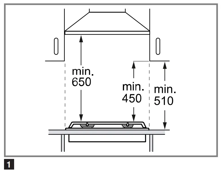
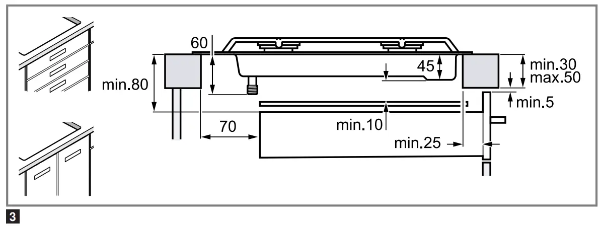
Always observe the minimum vertical distance to the hob
→ Fig.

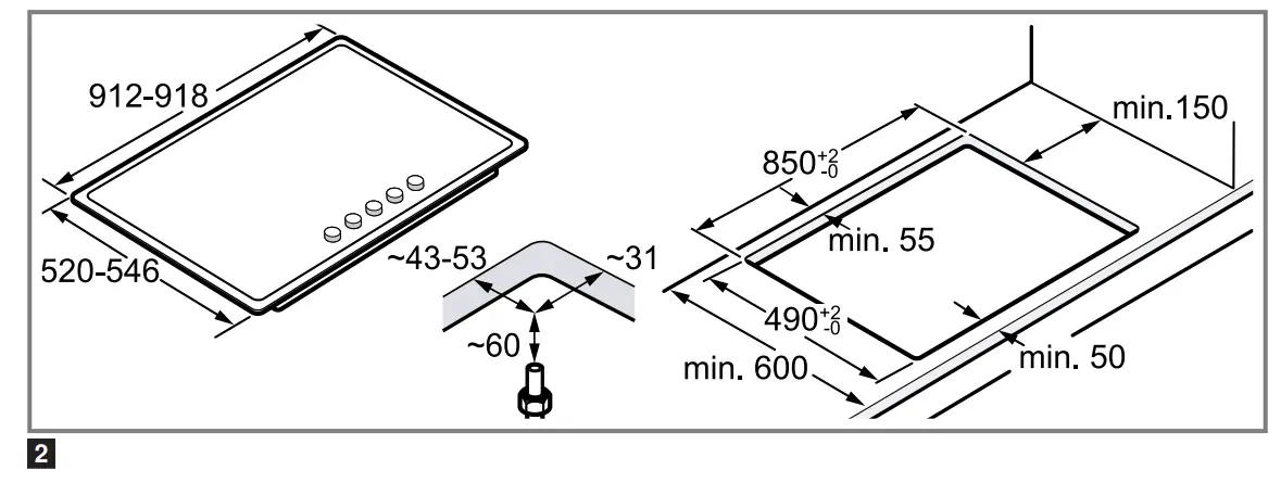
Preparing the units
- Make a cut-out in the worktop with the required dimensions.
→ Fig.
- Seal the cut surfaces of wooden work surfaces with a special glue seal to protect them from moisture.
- If there is no built-in oven underneath the hob, insert a non-flammable separator (e.g. metal or plywood) at a distance of 10 mm from the hob. This prevents access to the underside of the hob. The distance from the intermediate floor to the mains connection for the appliance must be at least 10 mm.
→ Fig. , → Fig. 
Positioning the appliance
Note: Do not remove the adhesive seal fitted on the lower edge of the hob. The adhesive seal prevents the penetration of liquids.
Do not use silicone to bond the appliance to the worktop.
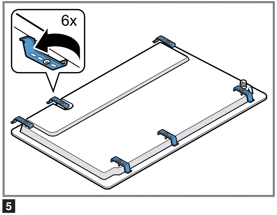
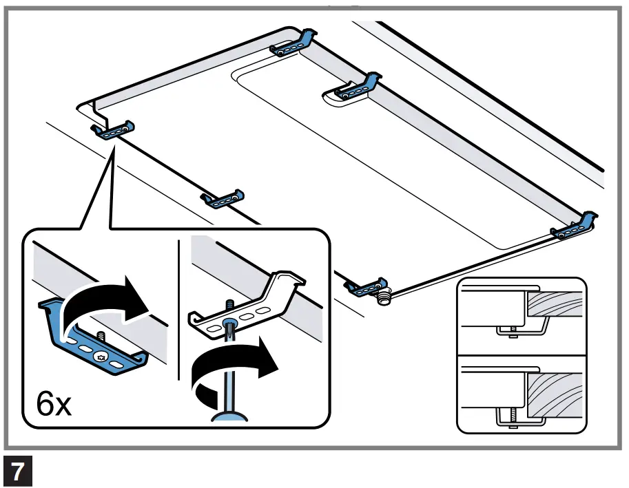
- Position the hob with the upper side facing down on a flat, stable surface.
- Loosen the screws on the brackets so they can turn freely. You do not need to fully undo the screws on the brackets.
→ Fig.
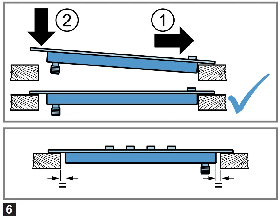
- Turn the hob around and insert it into the recess.
Insert the hob in the front of the recess.
→ Fig. - Turn the brackets and tighten them fully.
→ Fig.
The position of the brackets depends on the worktop thickness.
Removing the appliance
- Disconnect the appliance from the electricity and gas connections.
- Unscrew the brackets and proceed in reverse order.
Connecting the gas
Observe the country-specific guidelines.![]() CAUTION Risk of explosion!
CAUTION Risk of explosion!
A gas leakage may cause an explosion.
▶ If any connection is handled, check the seal.
- Arrange the gas connection so that the shut-off valve is accessible.
- Ensure that the information on the rating plate regarding the gas type and gas pressure complies with the local connection conditions.
- Connect the appliance to a fixed gas pipe or a flexible metal pipe.
- The flexible metal pipe must not come into contact with the moving parts of the unit in which the appliance is installed (e.g. a drawer) and must not be routed through any spaces which might become obstructed.
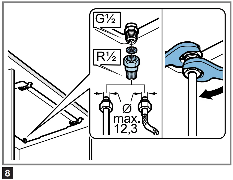
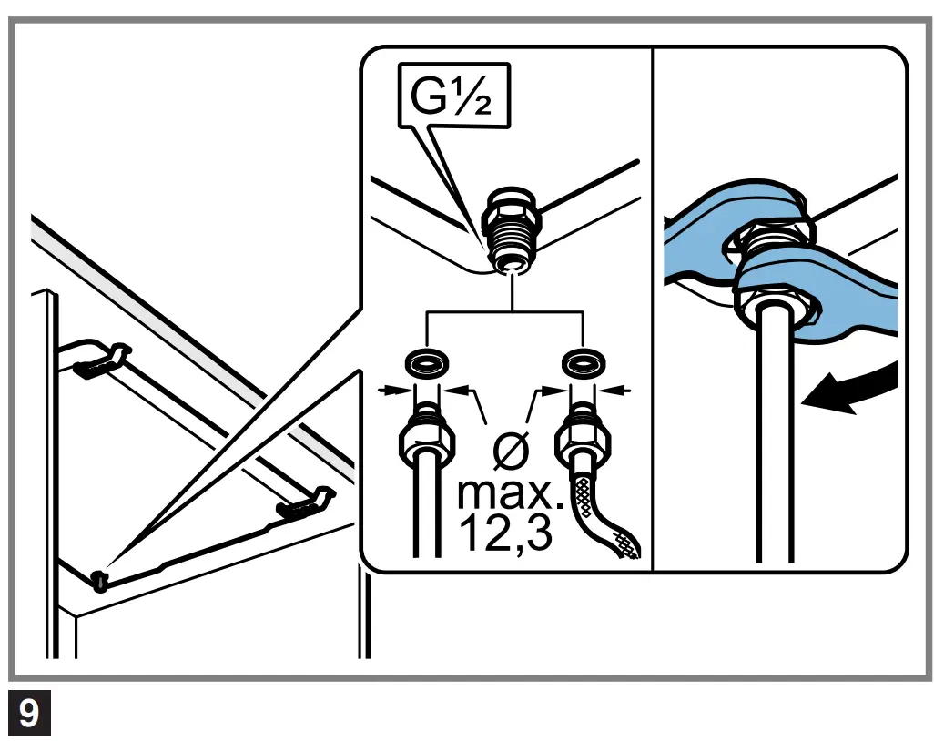
- Gas connection on the appliance: G 1/2.
Spare parts for gas connection
You can obtain the gas connection parts from the technical customer service.
| Connecting piece R 1/2″ | 00427950 |
Gas connection R 1/2
▶ Fit the seal and the connecting piece R 1/2 to the gas connection on the appliance.
→ Fig. ![]()
Gas connection G 1/2
▶ Insert the seal between the gas connection of the appliance and the gas supply.
→ Fig. ![]()
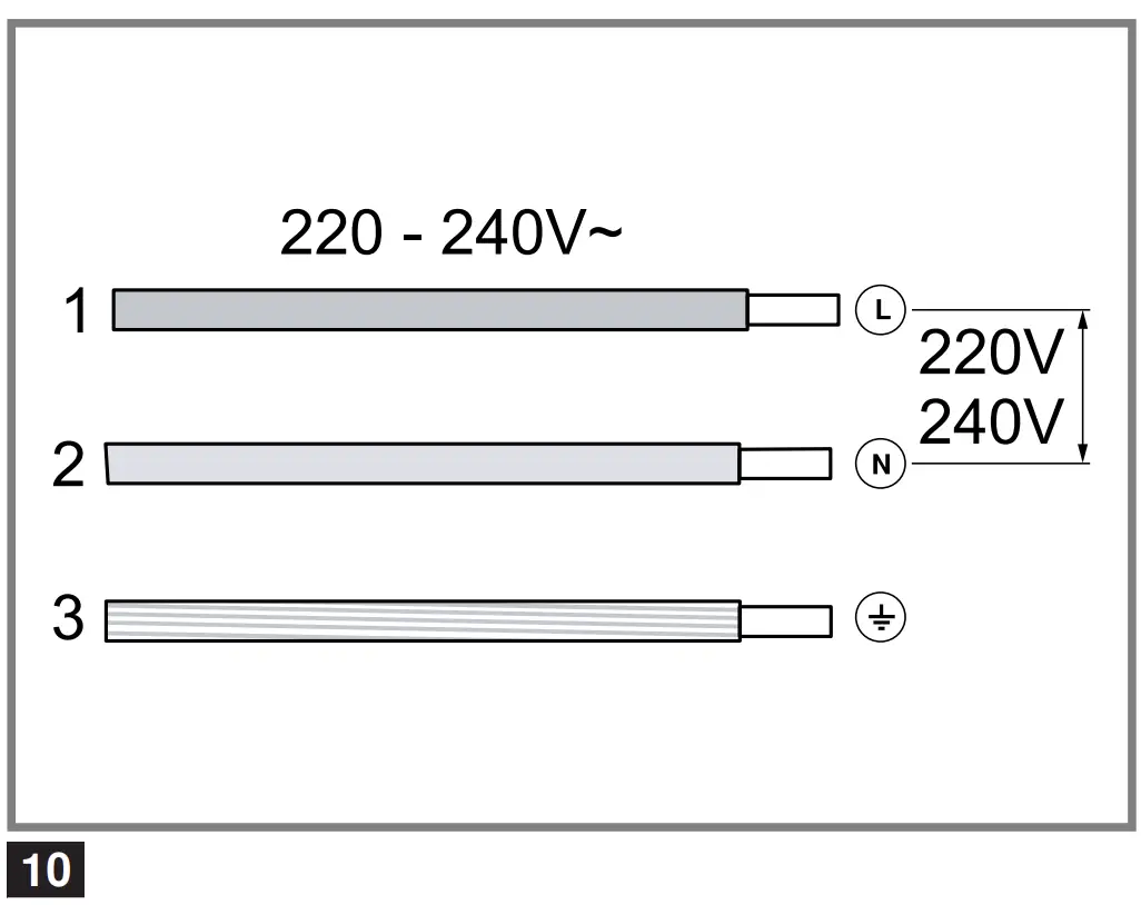
Electrical connection
Converting the gas type
- This appliance is type Y: The connection cable must only be replaced by technical customer service and not by the user. The cable type and the minimum cross section must be respected.
- The hobs are supplied with a power cord with or without a plug.
- Only connect appliances that are fitted with a plug to a correctly installed socket with protective earth conductor.
- If the plug is not accessible to the user, an all-pole isolating safety switch with a minimum contact opening of 3 mm must be provided.
→ Fig.


Converting the gas type
If the country’s regulations allow, this appliance can be adapted to other types of gas, if these are listed on the rating plate.
You can find the right parts in the bag that is supplied with the appliance or you can obtain them from customer service. The table → Fig. shows the right combination for the relevant burner and gas type.
| Economy burner | |
| Standard-output burner | |
| High-output burner | |
Dual-wok multi-crown burner
|
Tools
Contact technical customer service to purchase the relevant tools.
Removal lever 483196
Adjusting the taps
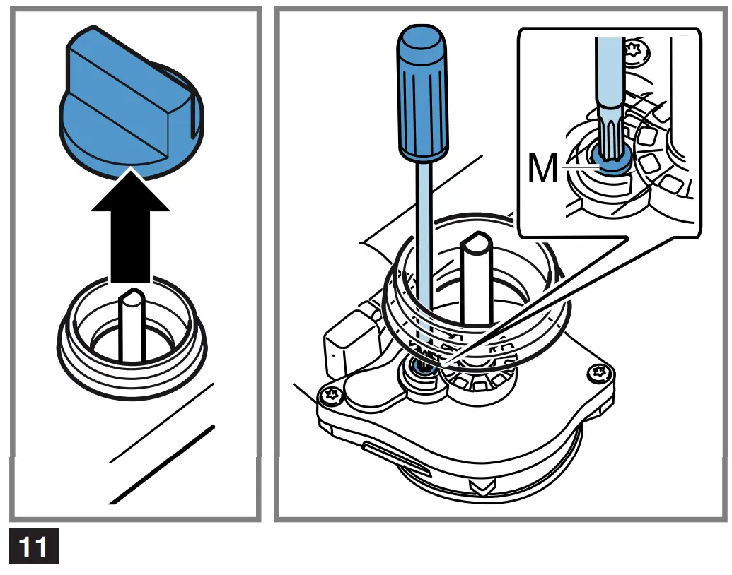
- Turn the rotary knobs to the minimum power position and pull them out.
- With the tip of the screwdriver, push down on the flexible rubber holder to access the bypass screw.
→ Fig. 11
Never remove the sealing ring. The sealing rings prevent liquids and dirt from finding their way into the appliance and impairing its ability to function properly. - When adjusting the bypass screws (M), refer to the table → Fig.
 .
.
‒ A: Firmly tighten the bypass screws.
‒ B: The bypass screws must be flush with the fitting.
→ Fig.


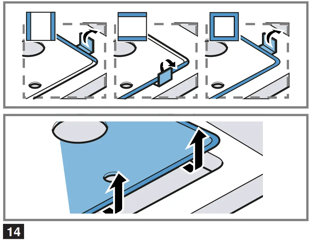
Removing the upper part of the appliance (glass plate with cut-out profiles)
- Remove the pan supports, burner caps, distributors and rotary knobs.
- Undo the screws on the burners.
→ Fig. - Move the removal lever under the metal cut-out profile into the area marked for the hob model and loosen the front clip fastener.
→ Fig.
Only use the lever under the cut-out profiles or the metal frame of the hob. - Carefully lift the glass plate with the cut-out profiles to release the rear clip fastener.


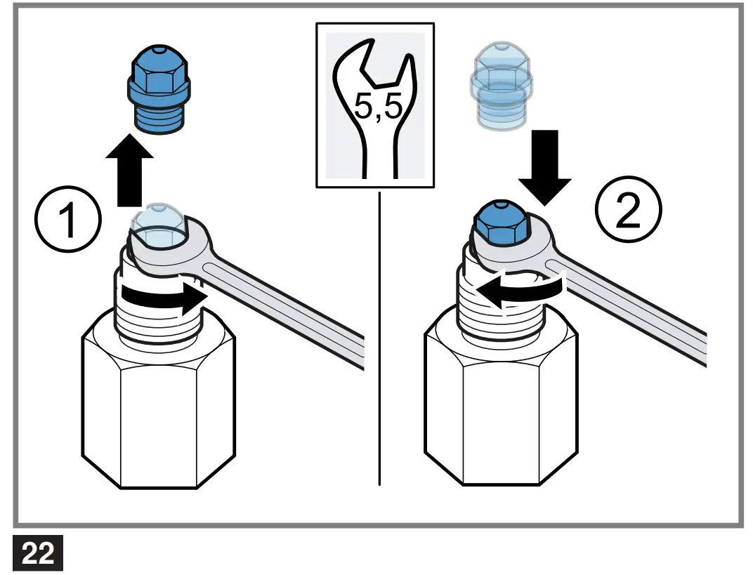
Replacing the nozzles
- Remove all pan supports, burner caps and distributors.
- Replace the nozzles using the appropriate wrench and tighten them carefully to guarantee the seal.
→ Fig.

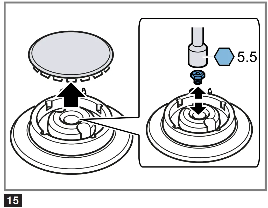
Ensure that the nozzle does not become detached during removal or fastening.
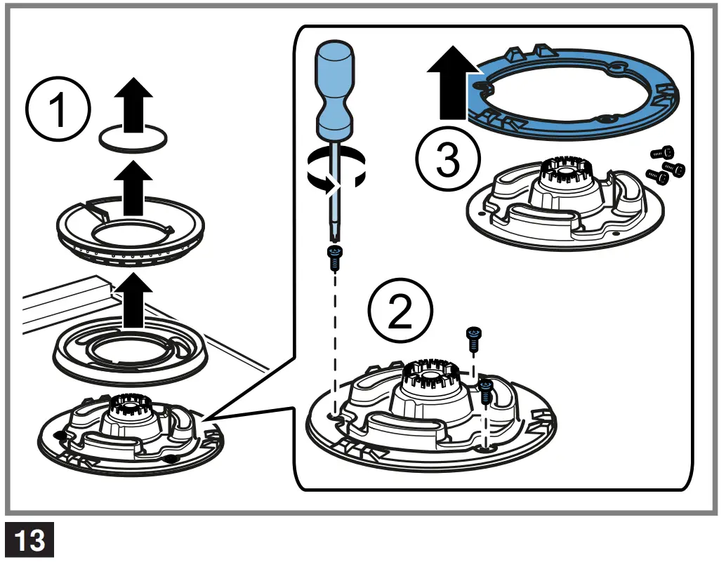
Replacing the outer flame nozzle on the multi-crown burner
Requirement: The upper part of the appliance has been removed. → “Removing the upper part of the appliance (glass plate with cut-out profiles)”,
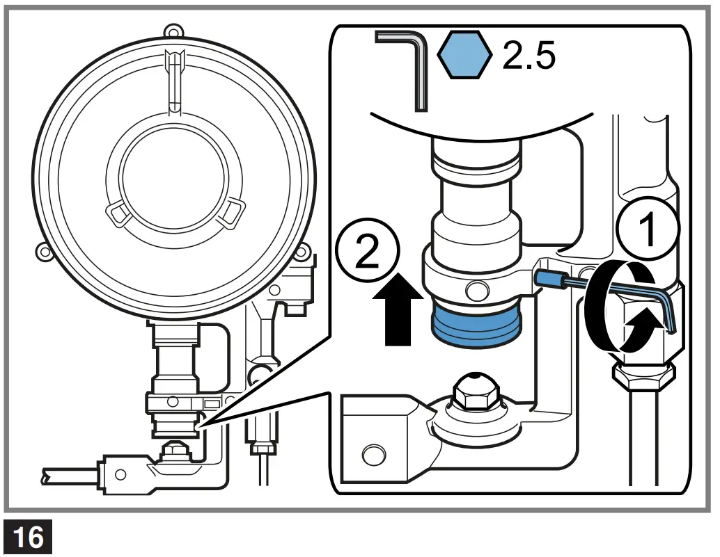
- To gain access to the main nozzle, loosen the fastening screw ① and pull the sleeve ② back.
→ Fig. - Remove the nozzle by turning it anti-clockwise ① and ② screw in the new outer flame nozzle ③.
→ Fig.
- Set the spacing of the adjustment sleeve for the air supply to dimension Z, as shown in the table
→ Fig.
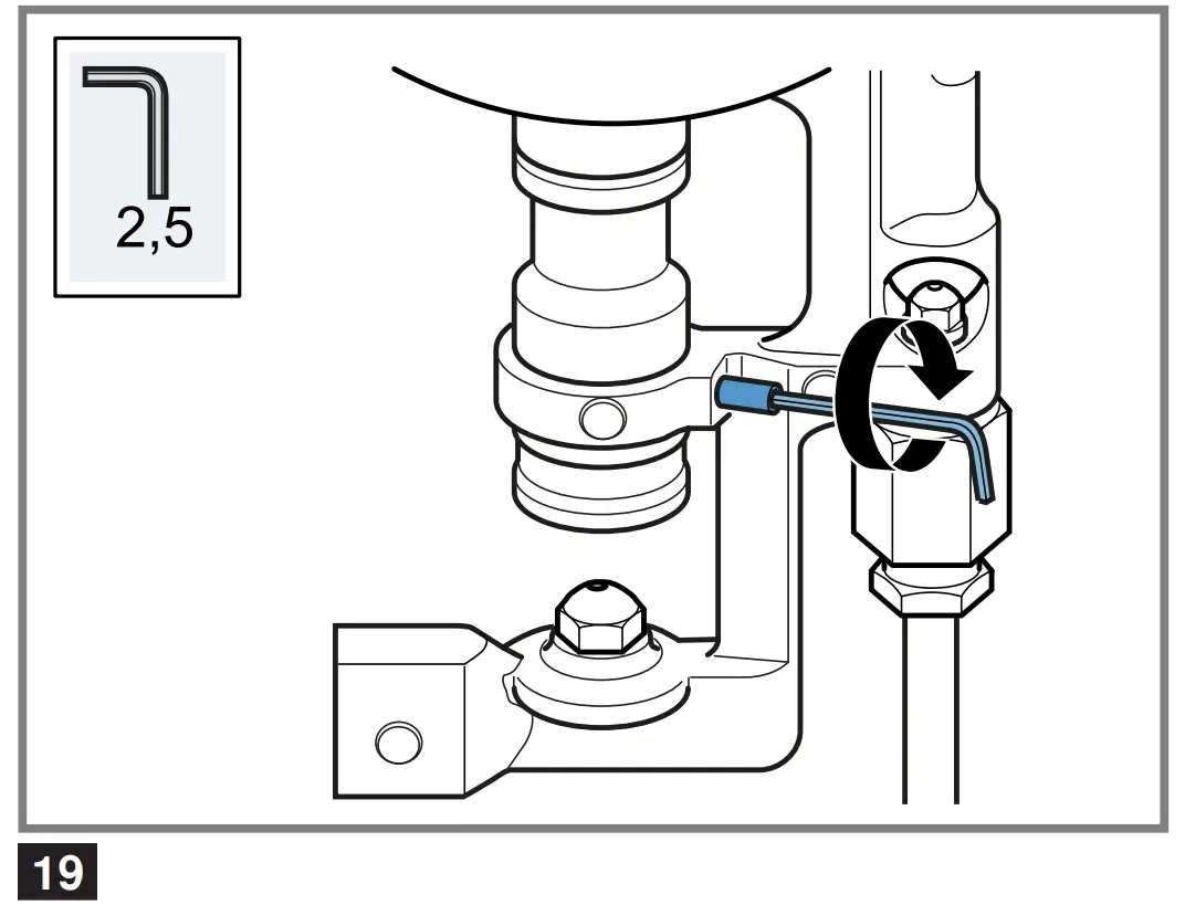
→ Fig. - Tighten the fastening screw.
→ Fig.


Replacing the inner flame nozzle on the multi-crown burner
Requirement: The upper part of the appliance has been removed. → “Removing the upper part of the appliance (glass plate with cut-out profiles)”,
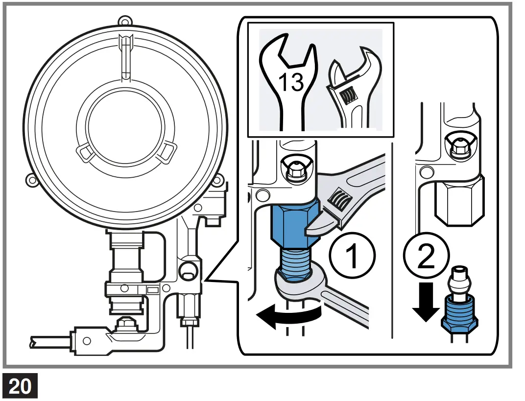
- Unscrew the tube by applying pressure to the sleeve in the opposite direction to hold it in place ① and pulling the tube out of the sleeve ②.
→ Fig. - Remove the sleeve.
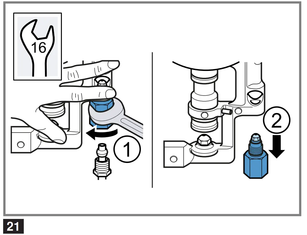
→ Fig. - Remove the inner flame nozzle from the sleeve and screw in the new nozzle.
→ Fig. - Screw the sleeve and the tube back into their original position.
Reinstalling the appliance
▶ Install the appliance components in reverse order.
Checking if equipment is working
- Check that turning the rotary knob between the position for maximum power and the position for minimum power does not cause the burner to go out or result in backfire.
- If the gas flow from the burner is not correct, in the table → Fig. , check whether the nozzle and the position of the bypass screw are correct.
Documenting the gas type conversion
▶ Attach the sticker showing the new gas type near to the rating plate.


