RE62 Universal Controller
UNIVERSAL CONTROLLER
RE62
USER’S MANUAL
1
RE62-09C-R1
2
User’s manual
Contents
1. APPLICATION…………………………………………………………………………………………………………………. 3 2. CONTROLLER SET…………………………………………………………………………………………………………. 3 3. BASIC REQUIREMENTS, OPERATIONAL SAFETY……………………………………………………………..4 4. INSTALLATION………………………………………………………………………………………………………………… 5
4.1. Mounting………………………………………………………………………………………………………………….. 5 4.2. External connection diagrams………………………………………………………………………………………6 4.3. Installation Recommendations……………………………………………………………………………………..7 5. Starting work……………………………………………………………………………………………………………………. 8 6. SERVICING…………………………………………………………………………………………………………………….. 9 6.1. Programming Controller Parameters……………………………………………………………………………10 6.2. Controller menu……………………………………………………………………………………………………….. 11 6.3. Setting Change……………………………………………………………………………………………………….. 12 6.4. Parameters description…………………………………………………………………………………………….. 12
6.4.1 Individual characteristic……………………………………………………………………………………….18 7. INPUTS AND OUTPUTS OF THE CONTROLLER……………………………………………………………….19
7.1 Measuring inputs………………………………………………………………………………………………………. 19 7.2 Outputs…………………………………………………………………………………………………………………… 20 8. CONTROL…………………………………………………………………………………………………………………….. 20 8.1 ON-OFF control………………………………………………………………………………………………………… 20 8.2 SMART PID algorithm………………………………………………………………………………………………..21
8.2.1 Auto-tuning……………………………………………………………………………………………………….. 21 8.2.2 Proceeding in case of an unsatisfactory PID control…………………………………………………23 9. ALARMS……………………………………………………………………………………………………………………….. 23 10. ADDITIONAL FUNCTIONS…………………………………………………………………………………………….. 25 10.1 Monitoring of control signal……………………………………………………………………………………….25 10.2 Manual control………………………………………………………………………………………………………… 25 10.3 Signal retransmission………………………………………………………………………………………………. 25 10.4 Digital filter…………………………………………………………………………………………………………….. 25 10.6. Default settings……………………………………………………………………………………………………… 27 11. RS-485 interface (OPTIONAL)…………………………………………………………………………………………27 11.1 Introduction……………………………………………………………………………………………………………. 27 11.2. Map of the registers…………………………………………………………………………………………………27 12. SOFTWARE UPDATE (OPTIONAL)…………………………………………………………………………………34 13. TECHNICAL DATA……………………………………………………………………………………………………….. 35 14. ORDERING CODE……………………………………………………………………………………………………….. 38
RE62-09C-R1
3
User’s manual
1. APPLICATION
The RE62 controller is destined to control the temperature and other physical quantities (pressure, humidity, level, etc.) in plastics, food, dehydration industries and other where there is a need to stabilize the changes of the measured value. The measuring input is universal for the thermoresistors, thermocouples or standard linear signals.
The controller allows dual-point control based on the PID or ON/OFF algorithm and alert signalization. The controller can be equipped with the relay outputs, continuous output and 24 V DC power output depending on the version.
The innovative SMART PID algorithm has been implemented in the controller.
All values and the configuration parameters of the controller are available via an optional RS485 communication interface.
The output signals are galvanically isolated from the input signals and power supply.
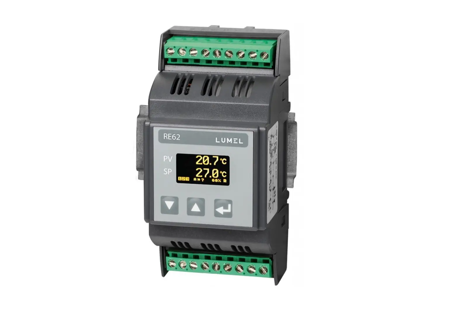
Figure 1. Overview of the controller
2. CONTROLLER SET
Complete set of the meter includes:
– controller
1 pc
RE62-09C-R1
4
User’s manual
3. BASIC REQUIREMENTS, OPERATIONAL SAFETY Symbols in this manual mean:
Warning! Warning about the potentially hazardous situations. Especially important, please read before connecting the device. Non-compliance with the comments marked by this symbol could result in serious injury and damage to the device.
Caution! Useful general notes. Please read them for easy operation. Should pay attention to them, if the device is not working as expected. Possible consequences in case of disregarding information!
In terms of operational safety the controller meets the requirements of the EN 61010-1 standard.
Remarks concerning safety: Assembly and installation of the electrical connections should be conducted only by a person authorised to perform assembly of electric devices.
Always check the connections before turning the meter on.
Removal of the meter housing cover during the warranty period voids the warranty.
The meter is designed to installation and usage in the industrial electromagnetic environment.
A switch or a circuit-breaker should be installed in the building or facility. It should be located near the device, easily accessible by the operator, and suitably marked.
RE62-09C-R1
5
4. INSTALLATION
User’s manual
4.1. Mounting
The RE62 controller is designed for installation in modular distribution boards on a 35 mm rail. The controller housing is made of plastic. Housing dimensions: 53 x 110 x 60.5 mm. There are screw terminal strips on the outer side of the controller which enable the connection of external wires of diameter up to 2.5 mm2. Dimensions of the controller are presented in Fig. 2.
Figure 2. Controller overall dimensions
RE62-09C-R1
6
4.2. External connection diagrams
230V N 24V OUT3 or OUT2 OUT1
supply
+ 24 V –
+ –
10 11 12 13 14 15 16 17 18
RE62
User’s manual
1 2 3 4 5 6 7 8 9
measuring signals
GND B A RS485
Figure 3. RE62 controller electrical connections
1 2 3 4 5 6
+ –
1 2 3 4 5 6
+ –
1 2 3 4 5 6
thermocouple J,K
1 2 3 4 5 6
voltage input ±60 mV
1 2 3 4 5 6
+ –
Resistance thermometer in 2-wire system
1 2 3 4 5 6
+ –
Resistance thermometer in 3-wire system
current input ±20 mA
voltage input ±10 V
Figure 4. Connections of measuring signals
RE62-09C-R1
7
User’s manual
13 15 17 14 16 18
receiver
OUT1, OUT2, OUT3 – relay
supply
13
receiver
14
OUT3 24 V DC, max. 40 mA
17 +
SSR
18 –
receiver
OUT1 voltage 0/5 V
supply
17 + 18 –
receiver, min. 1 k
OUT1 continuous voltage 0/10 V
17 + 18 –
receiver, max. 500
OUT1 continuous current 0/4..20 mA
Figure 5. Connection of the control / alarm outputs
4.3. Installation Recommendations
In order to obtain full noise immunity of the controller, it is recommended to observe the following principles:
do not supply the controller from the network, in the proximity of devices generating high pulse noise and do not apply common earthing circuits,
apply network filters, wires leading measuring signal should be twisted in pairs and for
the resistance sensors in the 3-wire connection they should use twisted wires of exactly the same length, diameter and resistivity protected by shielding, all shields should be one-side earthed or connected to the protection wire, the nearest possible to the controller, as a rule of thumb, wires transmitting different signals should be spaced as far as it is possible (at least 30 cm) and should be crossed only at the right angle of 90°.
RE62-09C-R1
8
User’s manual
5. STARTING WORK
After powering on, the controller performs the display test, displays the manufacturer’s logo, device type, firmware version and a controller serial number then displays a measured value and a set point.
The messages of the errors encountered in the operation of the controller may be displayed.
The PID control algorithm with a proportional band 30°C, integral time constant 300 seconds, derivative time constant 60 seconds and a pulse period 20 seconds are set by the manufacturer.
Change of the set point
Change of the set point is done by pressing the button or . New set point can be accepted by the button during 30 seconds
from last pressing of the button or otherwise a previous value will be restored. The parameters SPELL and SPLH set the change limitation.
measuring value set point
change acceptation
output activation
change of the set value up/down
RS485 reception / transmission (optional)
Figure 6. RE62 controller panel description
Monitoring of control signal
Measuring value
control signal
2 sec.
Auto-tuning start screen
Measuring value
auto-tuning function
2 sec.
Manual working mode
Auto-tuning mode
Figure 7. Menu of controller service
Measuring value Set point
2 sec.
Increasing set point Decreasing set point
active T
access code
N
Enter a code: 0
T correct code? N Incorrect code!
locking the changes
Parameter programming mode
3 sec.
6. SERVICING The controller service is presented in Fig. 7.
User’s manual
9
RE62-09C-R1
RE62-09C-R1
10
6.1. Programming Controller Parameters
User’s manual
Pressing and holding down during ca 2 seconds the button causes the entry to the controller menu. The menu can be protected by an access code. In case when giving a wrong value of the code, it is only possible to see settings through – without possibility of changes.
Figure 8 shows the menu structure in the programming mode. The transition between the levels is carried out by using the buttons
or
and the level selection by using the button . After
selecting the level, the transition between parameters is carried out
by using the buttons or . In order to change the setting proceed acc. to the section 6.3. In order to exit from the selected level, transit between parameters until appears the symbol […] and
press the button . n order to exit from the programming matrix to the normal work mode, transit between levels until appears the symbol […] and press the button . Transition to the higher level is
possible by simultaneously pressing the buttons and .
Some controller parameters can be invisible it depends on the current configuration. The description of parameters shows the Table 1. The return to the normal work mode follows also automatically after 30 seconds since the last button pressure.
RE62-09C-R1
11
User’s manual
6.2. Controller menu
INPUT
UNIT
Input Measurin parameter g unit
s
TYPE Input type
AUTO COMPENS COMPENS. ATION
Automatic compensa
tion enabled
Value of a manual
compensati on
DOT POINT
Displayed precision
OFFSET
Manually switch the measuring value by a set
point
FILTER
Constant value of the digital
filter
USER CHAR. X1
Individual characteri stic for a measurin
g input
USER CHAR X2
Individual characteri stic for a measurin
g input
USER CHAR Y1
Individual characteri stic for a measurin
g input
USER CHAR Y2
Individual characteri stic for a measurin
g input
…
Transition to the higher level
OUTPUT
Outputs parameter
s
FUNCTION 1
Output 1 function
TYPE 1
Output 1 type
FUNCTION 2
Output 2 function
FUNCTION 3
Output 3 function
ERROR
Signal when failure
IMPULSE 1/2/3
Pulse period of output 1/2/3
…
Transition to the higher level
REGULAT ALGORIT
ION
HM
Control Control parameter algorithm
s
TYPE
Type of control
HYSTER ESIS
Hysteresi s
MIN. REG.
Minimum control signal
MAX. REG
Maximum control signal
SELFTUNE MIN
Minimum set point for auto-
tuning
SELFTUN E MAX
Maximum set point for auto-
tuning
…
Transition to the higher level
PID
PID Paramete
rs
PROPOR TIONAL
Proportion al band
INTEGRAL
Integral time
constant
DIFFERE NTIAL
Derivative time
constant
…
Transition to the higher
level
ALARMS
Alarms parameter
s
SETPOINT 1/2/3
Set point for the alarm 1/2/3
DEVIATION 1/2/3
Deviation for the
alarm 1/2/3
HYSTER ESIS 1/2/3
Hysteresi s of the alarm
1/2/3
MEMORY 1/2/3
Memory of the alarm
1/2/3
…
Transition to the higher
level
SETPOINT
Set point parameter
s
VALUE Set point
UNIT
STEP
Time unit of Ramp
the set
step in
point ramp time units
LOW THRESHOLD
Lower limit of the set
point
UP THRESHOLD
Upper limit of the set
point
…
Transition to the higher level
RETRAN SMIT.
Retransmi ssion
parameter s
FUNCTION
Retransmi ssion
function
LOW THRESHOL
D
Retransmis sion lower
limit
UP THRESHO
LD
Retransmi ssion
upper limit
MANUAL VALUE
Value set manually
…
Transition to the higher
level
RS485 ADDRESS BAUDRATE MODE
…
Interface Device
parameter address in
s
MODBUS
network
Baud rate
Transmiss Transition to ion mode the higher
level
SERVICE
Service parameter
s
ACCESS
Access code
SELFTUN E
Auto-tuning function
LANGUA GE
Menu language selection
MENU TIMEOUT
Exit from the menu
time
…
RESET
Restoring default settings
Exit from the menu
…
Transition to the higher level
Figure 8. Menu of controller configuration
RE62-09C-R1
12
User’s manual
6.3. Setting Change
The change of parameter setting begins after pressing the
button during the display of the parameter name. Buttons and are used for the setting choice, and the button to accept.
The change cancellation follows after the simultaneous pressure of
the buttons pressure.
and or after 30 seconds since the last button
6.4. Parameters description
The list of parameters in the menu is presented in the Table 1.
Controller menu
Table 1.
Parameter
Parameter description
INPUT input parameters
UNIT
Displayed unit. The user-defined unit will be displayed in case of selecting the value OTHER. Defining your own units can only be performed with RS485 interface. The value OTHER is empty by default.
Default setting
°C
TYPE
Type of measuring input
PT100
Range of changes
°C °F OTHER
±10V input 10 V ±60mV input 60 mV ±20mA input 0/20 mA 4..20mA input 4/20 mA PT100 PT100 sensor
TCJ J type thermocouple TCK K type thermocouple
RE62-09C-R1
13
Automatic
AUTO COMPENS. compensation
ON
enabled/disabled
COMPENSATION
Value for a manual compensation
0.0
DOT POINT
Position of decimal point
0.0
OFFSET
Shift of measuring value
0.0
FILTER
Constant value of the digital filter
0.5 sec
Individual
characteristic for a
USER CHAR.X1
measuring input, point X1 (Fig. 9)
0
User’s manual
OFF/ ON
0.0..20.0 for input PT100
-20.0..60.0 °C 0 without a decimal
place 0.0 1 decimal place 0.00 2 decimal places
-100.0…100.0
0.5 sec 1.0 sec 3.0 sec 5.0 sec 10 sec 15 sec 20 sec
-9999..9999
Individual
characteristic for a
USER CHAR. X2 measuring input,
1
point X2 (Fig. 9)
Individual
characteristic for a
USER CHAR. Y1
measuring input, point Y1 (Fig. 9)
0
-9999..9999 -9999..9999
Individual
characteristic for a
USER CHAR. Y2
measuring input, point Y2 (Fig. 9)
1
-9999..9999
RE62-09C-R1
14
User’s manual
OUTPUT output parameters FUNCTION 1 Output 1 function
TYPE 1
Output 1 type
REGULATI NONE output disabled
ON
REGULATION control
signal
ABS. UPPER upper
absolute alarm
ABS. LOWER lower
absolute alarm
REL. UPPER upper
relative alarm
REL. LOWER lower
relative alarm
INNER – internal relative
alarm
OUTER – external relative
alarm
RETRANS. –
retransmission
SENSOR ERROR –
sensor failure alarm
RELAY
RELAY relay output SSR voltage output 0/5
V 0-20 continuous current
output 0..20 mA 4-20 continuous current
output 4..20 mA 0-10 continuous voltage
output 0..10 V
RE62-09C-R1
15
User’s manual
FUNCTION 2 Output 2 function
FUNCTION 3 Output 3 function
ERROR
IMPULSE 1 IMPULSE2
The control signal of proportional control output in the event of a sensor failure
Output 1 pulse period
Output 2 pulse period
NONE NONE
0.0
NONE output disabled REGULATION control
signal ABS. UPPER upper
absolute alarm ABS. LOWER lower
absolute alarm REL. UPPER upper
relative alarm REL. LOWER lower
relative alarm INNER – internal relative
alarm OUTER – external relative
alarm SENSOR ERROR sensor failure alarm
NONE output disabled REGULATION control
signal ABS. UPPER upper
absolute alarm ABS. LOWER lower
absolute alarm REL. UPPER upper
relative alarm REL. LOWER lower
relative alarm INNER – internal relative
alarm OUTER – external relative
alarm SENSOR ERROR sensor failure alarm
0.0..100.0
20.0 s 20.0 s
0.5..99.9 s 0.5..99.9 s
RE62-09C-R1
16
User’s manual
IMPULSE 3
Output 3 pulse period
REGULATION control parameters
ALGORITHM Control algorithm
TYPE
Type of control
HYSTERESIS Hysteresis
MIN. REG.
Minimum control signal
MAX. REG.
Maximum control signal
SELFTUNE MIN Lower limit for auto-tuning
SELFTUNE MAX Auto-tuning upper limit
PID PID parameters
PROPORTIONAL Proportional band
INTEGRAL
Integral time constant
DIFFERENTIAL Derivative time constant
ALARMS alarms parameters
SETPOINT 1 Set point for the absolute alarm 1
DEVIATION 1
Deviation from the set point of the relative alarm 1
HYSTERESIS 1 Hysteresis for the alarm 1
MEMORY 1 Memory of the alarm 1
SETPOINT 2 Set point for the absolute alarm 2
20.0 s
PID
REVERSE D
1.1 °C 0.0 % 100.0 % 0.0 °C 800.0 °C
30.0 °C 300 s 60.0 s
100.0 0.0 °C
2.0 °C OFF 100.0
0.5..99.9 s
ON-OFF on-off control PID PID control algorithm
DIRECT direct control (cooling)
REVERSED reverse control (heating) 0.2..100.0 °C 0.0..100.0 %
0.0..100.0 %
MIN..MAX *
MIN..MAX *
0.1..550.0 °C 0..9999 s
0.0..2500.0 s
MIN..MAX *
-200.0..200.0 °C
0.2..100.0 °C
OFF off ON – on MIN..MAX *
RE62-09C-R1
17
User’s manual
HYSTERESIS 2 Deviation from the set point of the relative alarm 2
0.0 °C
-200.0..200.0 °C
HYSTERESIS 2 Hysteresis for the alarm 2
2.0 °C
0.2..100.0 °C
MEMORY 2 Memory of the alarm 2
OFF
OFF off ON – on
SETPOINT 3 Set point for the absolute alarm 3
100.0
MIN..MAX *
HYSTERESIS 3 Deviation from the set point of the relative alarm 3
0.0 °C
-200.0..200.0 °C
HYSTERESIS 3 Hysteresis for the alarm 3
2.0 °C
0.2..100.0 °C
MEMORY 3 Memory of the alarm 3
OFF
OFF off ON – on
SETPOINT set point parameters
VALUE
Set point
0.0 °C
MIN..MAX *
UNIT
Time unit of the ramp rate
°C/min
°C/min °C/h
STEP
Set point ramp rate 0.0
0..999.9 (per a time unit)
LOW THRESHOLD
Lower limitation of -200.0 °C the fast set point change
MIN..MAX *
UP THRESHOLD Upper limitation of 1372.0 °C the fast set point change
MIN..MAX *
RETRANSMIT. retransmission parameters
FUNCTION
Value retransmitted on the continuous output
NONE
LOW
Lower limit of the
0.0
THRESHOLD signal to be
retransmitted
NONE function inactive INPUT measuring value
SETPOINT set point HYSTERESIS control
deviation MANUAL value set
manually
MIN..MAX *
RE62-09C-R1
18
User’s manual
UP THRESHOLD Upper limit of the signal to be retransmitted
100.0
MIN..MAX *
MANUAL VALUE Manual setting of
0.0
the output value
0.0..100.0
RS485 interface parameters
ADDRESS Device address in
1
MODBUS network
1..247
BAUDRATE Baud rate
9600
4800 bit/s 9600 bit/s 19200 bit/s
MODE
Transmission
8n2
8n2
mode
8e1
8o1
8n1
SERVICE service parameters
ACCESS
Access code to
0
change controller
settings
0..9999
SELFTUNE
Auto-tuning function
ON
OFF locked
ON – available
LANGUAGE Menu language selection
POLISH
POLISH ENGLISH
MENU TIMEOUT Automatic exit
30 s
from the menu
time
0..9999 s
RESET
Restoring default settings
OFF
OFF ON
*) The MIN and MAX values depend on the input type. See Table 2.
Parameters depending on the measured range
Input input ±10 V input ±60 mV input ±20 mA Input 4..20 mA
MIN -3000.0 -3000.0 -3000.0 -3000.0
Table 2.
MAX 3000.0 3000.0 3000.0 3000.0
RE62-09C-R1
19
PT100 sensor J type thermocouple K type thermocouple
-100 °C -100 °C -100 °C
6.4.1 Individual characteristic
User’s manual
850 °C 1200 °C 1372 °C
The individual characteristic enables the conversion of the measuring value to the displayed value. It is used to visualize the measurements of non-electrical quantities using the non-electrical transducers of the standard quantities. A conversion is done by approximation with a straight line through the points which are the characteristic parameters (Figure 9).
Displayed value
Y2
Y1
X1
X2 measuring value
Figure 9. Individual characteristic
Example: A pressure transducer with a range of 0-500 Pa and the voltage output of 0-10 V is connected to the input voltage with a
range of 10 V. Set the individual characteristics as follows:
X1 0 (lower measuring value) X1 10 (upper measuring value) Y1 0 (lower output value of the pressure transducer) Y1 500 (upper output value of the pressure transducer) The meter shows the value directly in Pa after including the individual characteristic.
The individual characteristics is switched off by setting its default parameters (X1 = 0, X2 = 1, Y1 = 0, Y2 = 1)
RE62-09C-R1
20
User’s manual
7. INPUTS AND OUTPUTS OF THE CONTROLLER
7.1 Measuring inputs
Measuring input is the source of the measuring value used for control and alarms.
Measuring input is a universal input capable of accommodating various sensors or standard signals. Input signal is selected with a TYPE parameter in INPUT menu. Position of the decimal point that determines measuring value and set point is set through the DOT POINT parameter. The individual characteristics can be set for the linear inputs (USER CHAR.X1.Y2 parameters) to convert the value of the measuring signal to the measuring value according to the user’s needs (Fig. 9). Correction of the indicated measuring value is done through the COMPENSATION parameter.
7.2 Outputs
The controller has a maximum of three outputs. Each of them can be set for control or alarm.
For the proportional control (with the exception of the analog outputs) a pulse period is also set. Pulse period is a time between two subsequent input engagements during proportional control. Pulse period length should be adjusted for the dynamic properties of the object and characteristics of the output device. It is recommended to use SSR transmitter for quick processes. Relay output is used for a contactor control in the slow-changing processes. Long pulse periods for quick-change processes may cause unnecessary oscillation. In theory, the shorter pulse period is, the better the control, however for the relay output a period should be as large, as possible to optimize lifespan of the relay.
Pulse period setting recommendations
Output
Pulse period
Electromagnetic transmitter
Recommended > 20 s, min. 10 s
Min. 5 s
Transistor output
1..3 s
Table 3
Load 5 A/230 V
1 A/230 V semiconductor transmitter SSR
RE62-09C-R1
21
User’s manual
8. CONTROL
8.1 ON-OFF control When high accuracy of a temperature control is not required,
especially for the high time constant and small delay, it is possible to use ON-OFF control with hysteresis. The advantages of this method of control are simplicity and reliability. Disadvantage, however, are the oscillations even at low hysteresis values.
output on
hysteresis
off
set point
measuring value
Figure 10. Heating output operation
8.2 SMART PID algorithm
When high precision of the temperature control is necessary, it is recommended to use PID algorithm. SMART PID algorithm used, ensures increased precision in the extended range of the control object classes.
Tuning of the controller to object is achieved by manual setting of the proportional term, derivation term or difference term or automatically by auto-tuning function.
8.2.1 Auto-tuning
The controller has the function to select PID settings. These settings ensure the optimal control in most cases.
To begin the auto-tuning, move to the auto-tuning message
RE62-09C-R1
22
User’s manual
(acc. to the Fig. 7) and hold down the button
for at least 2
seconds. If the control algorithm is set to ON-OFF or the auto-tuning function is locked, then the auto-tuning message is hidden. For a correct realization of the auto-tuning function, it is required to set the parameters SELFTUNE MIN and SELFTUNE MAX. The parameter SELFTUNE MIN should be set to the value corresponding to the measuring value at the control switched off. For object temperature control, you can set 0 ºC. The parameter SELFTUNE MAX should be set on the value corresponding to the maximum measuring value when the control is switched on the full power.
The duration of auto-tuning depends on dynamic object properties and can last maximally 10 hours. During auto-tuning or directly after it, over-regulations can occur and because of this set a smaller set point if possible.
The auto-tuning is composed of following stages:
auto-tuning process
– calculation of PID settings and storage them in the non-volatile memory – start of the PID control with new settings
auto-tuning successfully completed
– transition to the manual working mode – displaying an error code which needs to be confirmed
The auto-tuning process will be stopped without counting PID settings, if a supply decay occurs or the button will be pressed .
In this case, the control with current PID settings will be started. If the auto-tuning does not end with success, then an error code
will be displayed acc. to the Table 4.
RE62-09C-R1
23
User’s manual
Table 4.
Error code
Reason
Proceeding
ERROR 1 The set point is incorrect.
Change a set point or the parameters SELFTUNE MIN, SELFTUNE MAX.
ERROR 2 The button was pressed .
ERROR 3 The maximal auto-tuning Check, if the sensor is correctly
duration time has been situated, if the set point value is not
exceeded.
set too higher for the given object.
ERROR 4 The maximal time for switching has been exceeded.
ERROR 5 The input measuring range Take note of the way to connect
has been exceeded.
the sensor. Do not allow that the
overflow results in exceeding of the
input measuring range.
ERROR 6 Very non-linear object, Carry out the auto-tuning again. If enabling to obtain correct that does not help, choose PID values of PID parameters, or parameters manually. an interference has occurred.
8.2.2 Proceeding in case of an unsatisfactory PID control It is recommended to choose PID parameters, changing the
value in a twice higher or twice less. During the change, one must respect following principles. a) oscillations
– increase the proportional band – increase the integral time – decrease the derivative time b) over-regulations – increase the proportional band – increase the integral time – increase the derivative time c) instability – decrease the proportional band – decrease the derivative time
RE62-09C-R1
24
d) free jump response
decrease the proportional band
decrease the integral time
User’s manual
9. ALARMS
The controller has three alarms, which can be assigned to each output. Alarm configuration requires to select an alarm type by setting outputs parameter FUNCTION 1, FUNCTION 2, FUNCTION 3 for the appropriate alarm type. Available types of alarms are given on the Figure 10.
Alarm set point
Alarm set point
Deviation > 0 Set point in main circuit
Deviation < 0
Absolute upper
Absolute lower
Relative upper
Deviation > 0 Set point in main circuit
Deviation < 0
Deviation > 0 Set point in main circuit
Deviation < 0
Deviation > 0 Set point in main circuit
Deviation < 0
Relative lower
Relative internal
Relative external
Figure 11. Alarm types
The set point for absolute alarms is the value defined by the parameter SETPOINT x, and for relative alarms, it is the deviation from the set point – the parameter HYSTERESIS x. Alarm hysteresis, the zone around the set point in which the input state is not changed is defined by the HYSTERESIS x parameter.
It is possible to set the alarm latch to save the status of the
RE62-09C-R1
25
User’s manual
alarm after an alarm condition withdraw (the parameter MEMORY x = ON). The alarm is signaled by an alarm indicator flashing on a display. Alarm memory reset can be done by simultaneously pressing
the buttons interface.
and
in the normal work mode or via the
10. ADDITIONAL FUNCTIONS
10.1 Monitoring of control signal
To display the control signal press the button
until the
control signal will appear on the display as shown in Figure 7. The
return to displaying set point has a default setting of 30 seconds but it
can be changed or disabled by the parameter MENU TIMEOUT.
10.2 Manual control
The entry to the manual control mode follows after holding the
button down
during the control signal display. The controller
interrupts the automatic control and begins the manual control of the
output. The buttons
and are used for changing the control
signal. The exit to the normal work mode follows after pressing the
button
.
10.3 Signal retransmission
Continuous output may be used for retransmission of the selected value, e.g. for registering object temperature or copying set point in multi-zone furnaces.
Signal retransmission is possible if the output 1 is a continuous type of output. Start a retransmission configuration by setting the parameter FUNCTION 1 to RETR. Additionally, it is necessary to set upper and lower limit of the signal to be retransmitted (LOW THRESHOLD and UP THRESHOLD). Selection of the signal to be retransmitted is done by the parameter FUNCTION in RETRANSMIT. menu. It is possible to manually set the signal on the continuous output by entering the values in MANUAL VALUE menu.
RE62-09C-R1
26
User’s manual
10.4 Digital filter
You can change the time constant of the digital filter if the measuring value is unstable. When using this feature, use the lowest filter time constant value that allows for the stable measuring value. When the time constant is too high, it may cause the control to become unstable. The time constant may be set from 0.5 to 20 seconds.
10.5 User unit (optional) RE62 controller can display the unit of the measuring value
defined by the user. eCon software should be used to edit and save the unit. The unit can be saved via the optional communication interface RS-485.
The image of the measuring value units uses 18×24 points of a display. This area is divided into 3 lines and each line on the 18 vertical lines with 8 points. One byte of data corresponds to each line, in which the value of 1 in a given field corresponds to turning on a given point on the display, the value 0 – turning off a given point on the display. The definition of the entire image creates a string of 54 bytes stored in 16-bit registers from the address 4500 of the controller. The 8-bit values of the lines in the 16-bit registers are arranged as shown in Figure 11.
0
18
1
2
01
…
16 17
3
4
5
18 19
…
6
34 35 24
7
36 37
…
52 53
RE62-09C-R1
27
User’s manual
MSB
LSB
Rej4500+N = 15 14 13 12 11 10 9
8
7
6
5
4
3
2
1
0
Line 1+N·2
Line 0+N·2
N = {0…26}
Figure 12. Entering the line value in the 16-bit register
10.6. Default settings
Factory settings can be restored by pressing and holding the , buttons within 1 second after switching the power on. Once the start logo appears, the buttons should be released. Restoring factory settings will be confirmed with an appropriate message (SET DEFAULT).
10.7. Detection of sensor failure
In the event of sensor failure manifesting itself in exceeding the lower or upper measuring range (shorting or opening of the measuring line), it is possible to react accordingly to the alarm output. To do this, set the SENSOR ERROR value as a function of the corresponding controller output. When a failure occurs, the selected output will be activated and the alarm icon will be visible on the display. After the failure ceases, the selected output will be released, and the icon signaling the alarm, depending on the option of alarm memory, will be turned off or will flash until the alarm is manually reset.
11. RS-485 INTERFACE (OPTIONAL)
11.1 Introduction
RE62 controller can be equipped with RS-485 serial interface
with implemented MODBUS communication protocol.
List of RE62 controller serial interface parameters:
device address:
1..247
baud rate:
4800, 9600, 19200 bit/s
operating mode:
RTU
RE62-09C-R1
28
User’s manual
transmission mode:
8n2, 8e1, 8o1, 8n1
data format:
integer (16 bit), float (32 bit), float
(2×16 bit)
maximum response time:
500 ms
maximum number of registers 100
read/written in one command
RE62 controller uses following protocol functions: Table 5.
Function
Meaning
3
Readout of n-registers
6
1 register writing
16
N-registers writing
17
Slave device identification
11.2. Map of the registers
In the RE62 controller, data are placed in 16 and 32-bit registers. Process variables and controller parameters are placed in the address area of registers in a way depended on the variable value type. Bits in 16-bit register are numbered from the youngest to the oldest (b0-b15). The 32-bit registers contain numbers of float type in IEEE-754 standard. Table 6 shows the registers ranges. 16-bit registers are shown in Table 7 and 10.
32-bit registers with their corresponding 2×16 bit registers are shown in Table 11. The register addresses in the tables are physical addresses.
Address range 4000 4073 4500 4526 6000 –
Value type
Integer (16 bits) Integer (16 bits)
Float
Table 6.
Description
Controller configuration. Value set in the 16-bit register. The user-defined graphical icon representing the unit of the measuring value. Value is set in the two following 16-bit
RE62-09C-R1
29
User’s manual
6018
7000 7018
7500 7509
(2×16 bits, byte sequence 3210) Float
(2×16 bits, byte sequence 1032) Float (32 bits)
registers. Registers contain the same data as 32-bit registers from the area 7500. Readout registers. Value is set in the two following 16-bit registers. Registers contain the same data as 32-bit registers from the area 7500. Readout registers. Value set in the 32-bit register. Readout registers.
Configuration registers of RE62 controller
Table 7.
Measuring input
4000 RW Selection of the measurement loop (range)
0 voltage input ±10 V 1 voltage input ±60 mV 2 current input ±20 mA 3 current input ±4..20 mA 4 PT100 input 5 TC J input 6 TC K input
4001 RW Displayed precision
0 0 1 0.0 2 0.00
4002 RW Averaging time of the measurement 5, 10, 30, 50, 100, 150, 200 (x100ms)
4003 RW Individual characteristic (X1)
-9999..9999
4004 RW Individual characteristic (X2)
-9999..9999
4005 RW Individual characteristic (Y1)
-9999..9999
4006 RW Individual characteristic (Y2)
-9999..9999
4007 RW Compensation
0..200 for input PT100 -200..600 for input TCJ/TCK
4008 RW Unit
0 Celsius 1 Fahrenheit 2 user defined
4009 RW Automatic compensation
0 off 1 on
Outputs
RE62-09C-R1
30
4010 RW Output 1
4011 RW Output 1 type
4012 RW Output 2
4013 RW Reserved 4014 RW Output 3
4015 RW Reserved 4016 RW The control signal of proportional
control output in the event of a sensor failure 4017 RW Minimum time of output 1 engagement (pulse)
User’s manual
0 off 1 control signal 2 upper absolute alarm 3 lower absolute alarm 4 upper relative alarm 5 lower relative alarm 6 internal relative alarm 7 external relative alarm 8 retransmission 9 sensor error alarm
0 relay 1 voltage output 0/5 V 2 continuous current output 4-20 mA 3 continuous current output 0-20 mA 4 continuous voltage output 0-10 V
0 off 1 control signal 2 upper absolute alarm 3 lower absolute alarm 4 upper relative alarm 5 lower relative alarm 6 internal relative alarm 7 external relative alarm 9 sensor error alarm
0 off 1 control signal 2 upper absolute alarm 3 lower absolute alarm 4 upper relative alarm 5 lower relative alarm 6 internal relative alarm 7 external relative alarm 9 sensor error alarm
0..1000 (x 0.1 %)
0..999 s
RE62-09C-R1
31
User’s manual
4018 RW Minimum time of output 2 engagement (pulse)
0..999 s
4019 RW Minimum time of output 3 engagement (pulse)
0..999 s
4020 RW Shift of measuring value
-1000…1000 (x0.1)
Control parameters
4021 RW Control algorithm
0 ON/OFF 1 – PID
4022 RW Type of control
0 direct control (cooling) 1 reverse control (heating)
4023 RW Hysteresis
2..1000 (x 0.1)
4024 RW Minimum control signal
0..1000 (x 0.1)
4025 RW Maximum control signal
0..1000 (x 0.1)
4026 RW Minimum control value for autotuning
0..1000 (x 0.1)
4027 RW Maximum control value for autotuning
0..1000 (x 0.1)
4028 RW Reserved
PID Parameters
4029 RW Proportional band
1..5500 (x 0.1)
4030 RW Integral constant
0..9999
4031 RW Derivative constant
0.0..25000 (x 0.1)
4032
Reserved
Alarms parameters
4033 RW Set point of the absolute alarm 1 -30000..30000 (x 0.1)
4034 RW Deviation from the set point of the -2000..2000 (x 0.1) relative alarm 1
4035 RW Hysteresis for the alarm 1
2..1000 (x 0.1)
4036 RW Memory of the alarm 1
0 off 1 on
4037 RW Set point of the absolute alarm 2 -30000..30000 (x 0.1)
4038 RW Deviation from the set point of the -2000..2000 (x 0.1) relative alarm 2
4039 RW Hysteresis for the alarm 2
2..1000 (x 0.1)
4040 RW Memory of the alarm 2
0 off 1 on
RE62-09C-R1
32
User’s manual
4041 RW Set point of the absolute alarm 3 -30000..30000 (x 0.1)
4042 RW Deviation from the set point of the -2000..2000 (x 0.1) relative alarm 3
4043 RW Hysteresis for the alarm 3
2..1000 (x 0.1)
4044 RW Memory of the alarm 3
0 off 1 on
4045
Reserved
Set point parameters
4046 RW Set point
-2000..13720 (x 0.1)
4047 RW Unit of the set point ramp
0 – °C/MIN 1 – °C/h
4048 RW Ramp step (in ramp units)
0..9999 (x 0.1)
4049 RW Lower limitation of the set point
0..-2000 (x 0.1)
4050 RW Upper limitation of the set point
0..13720 (x 0.1)
4051
Reserved
Retransmission parameters
4052 RW Function retransmitted
0 – NONE 1 – INPUT 2 – SETPOINT 3 – DEVIATION 4 – MANUAL
4053 RW Lower value
-2000..13720 (x 0.1)
4054 RW Upper value
-2000..13720 (x 0.1)
4055 RW Manual value
0..1000 (x 0.1)
4056
Reserved
RS-485 interface parameters
4057 RW Device address
1..247
4058 RW RS-485 baud rate
0 4800 1 9600 2 – 19200
4059 RW RS-485 mode
0 8n2 1 8e1 2 8o1 3 8n1
4060 RW Apply the changes RS-485
0 no changes 1 apply the settings
RE62-09C-R1
33
4061
Reserved
User’s manual
Service parameters
4062 RW Menu locking password
0 no password 1..9999
4063 RW Availability of auto-tuning function 0 none 1 – available
4064 RW Language
0 Polish 1 English
4065 RW Menu exit delay time
0..9999
4066 RW Restore default settings
0 no changes 1 restore parameters
4067 R Serial number MSB
–
4068 R Serial number LSB
–
4069 R Software version
–
4070 R Status of a device
Bit mask based on Table 8
4071 R Ordering code (configuration)
Bit mask based on Table 9
4072 R Special build number (KWS)
0 standard version
4073 RW Save parameters in non-volatile memory
0 don’t save 1 save
RE62 controller status
0 Alarm 1 status: 0 no alarm, 1 alarm active 1 Alarm 2 status: 0 no alarm, 1 alarm active 2 Alarm 3 status: 0 no alarm, 1 alarm active 3 KL1 button status: 0 released, 1 – pressed 4 KL2 button status: 0 released, 1 – pressed 5 KL2 button status: 0 released, 1 – pressed 6 Reserved 7 Retransmission enabled
Table 8.
8 Control: 0 automatic, 1 – manual 9 Auto-tuning enabled 10 Auto-tuning unsuccessfully completed 11 Upper limit overrun in a measuring loop 12 Lower limit overrun in a measuring loop 13 Reserved 14 Calibration error 15 Controller memory checksum error
RE62 controller configuration
0..2 OUT1: 0 none, 1 relay, 2 0..10 V, 3 0..20 mA, 4 0/5 V 3 OUT2: 0 none, 1 – relay 4 OUT3: 0 24 V DC or none, 1 relay
5 RS-485: 0 none, 1 – present 6..15 Reserved
Table 9.
RE62-09C-R1
34
User’s manual
User unit registers of RE62 controller
Table 10.
User unit
4500
RW
Image bit data of a graphic symbol of the measuring value unit as shown in Figure 11. Lines 1, 0.
4501 RW Lines 3, 2
…
RW
…
RW
…
RW
4526 RW Lines 53, 52
Measurement registers of RE62 controller
Table 11.
Measurements
6000/7000 7500 R Displayed value
6002/7002 7501 R Measuring value
6004/7004 7502 R Thermocouple terminal temperature
6006/7006 7503 R Thermocouple terminal temperature with correction
6008/7008 7504 R Value from AC converter
6010/7010 7505 R Value from AC converter averaged
6012/7012 7506 R Control signal
6014/7014 7507 R Current set point
6016/7016 7508 R Reserved
6018/7018 7509 R Reserved
12. SOFTWARE UPDATE (OPTIONAL)
A feature implemented in the RE62 controller enables to upgrade firmware using a PC with e-Con software installed. Update can be done via controller’s optional communication interface RS485. A PC requires for communication a RS-485 converter connected to USB port, for example PD10 converter.
13. TECHNICAL DATA
Measuring ranges:
Voltage measurement range Un:
-72 mV … -60 mV … 60 mV … 72 mV input resistance > 1 M
-12 V … -10 V … 10 V … 12 V
input resistance > 1 M
Current measurement range In: -24 mA … -20 mA … 20 mA … 24 mA input resistance < 50 1%
RE62-09C-R1
35
User’s manual
Temperature measurement – Pt100: -100 °C…850 °C
sensor current < 300 A
Temperature measurement – J thermocouple:
-100 °C…1200 °C
Temperature measurement – K thermocouple:
-100 °C…1370 °C
Preheating time:
30 minutes
Intrinsic error:
(0.2% of a range + 1 digit)
Additional errors in rated operating conditions: compensation of reference junction temperature changes 0.2% of the range compensation of resistance of wires changes 0.2% of the range from ambient temperature changes (0.1% of the range /10 K)
Averaging time: 0.5 s (default)
External transducers supply output (OUT3)*: 24 V 15% 40 mA
Relay output (OUT1, OUT2, OUT3):
NO contacts
load 250 V~/5 A~ switching number 1×10⁵
Analog output (OUT1)*: Serial interfaces*:
current 0/4..20 mA 0.2% (Ro 250 ) voltage 0..10 V 0.2% voltage 0/5 V RS-485, address 1..247; 8N2, 8E1, 8O1, 8N1 modes; baud rate 4.8, 9.6, 19.2 kbit/s,
RE62-09C-R1
36
User’s manual
Broadcast address: 253 transmission protocol: modbus RTU response time: 100 ms
Protection grade: from the front from terminals side
Power consumption in supply circuit:
IP 30 IP 20 5 VA
Weight
< 0.2 kg
Overall dimensions
53 x 110 x 60.5 mm
Rated operating conditions.
– supply voltage 22..60 V AC 50..400 Hz / 20..60 V DC (terminals 11-12)
60..253 V AC 40..400 Hz / 60..300 V DC (terminals 10-11)
– ambient temperature
-10 .. 23 .. +55 °C
– storage temperature
– 25 .. +75 °C
– humidity
< 95% (condensation of water vapor
not permissible)
– external magnetic field
0..40 ..400 A/m
– long-term overload: voltage, current measurement 20 %
– short-term overload (1 s)
sensors inputs 10 V
voltage inputs
2 Un
current inputs
10 In
– working position
vertical
warm-up time
15 min.
Readout field:
OLED display 128×64 points, amber
RE62-09C-R1
37
Electromagnetic compatibility: – noise immunity acc. to EN 61000-6-2 – noise emission acc. to EN 61000-6-4
User’s manual
Safety requirements: according to EN 61010-1 standard
· isolation between circuits: basic · installation category III, · pollution grade 2, · maximum phase-to-earth operating voltage:
– for supply circuit 300 V – for measuring input 50 V – for remaining circuits 50 V
· altitude a.s.l. < 2,000 m *) presence of the output depends on the regulator version
RE62-09C-R1
38
14. ORDERING CODE
User’s manual
Ordering Code Description
RE62 11100M0* RE62 21100M0* RE62 41100M0*
3x relay output, RS-485, supply 22 V a.c./d.c. or 230 V a.c./d.c., documentation and descriptions in Polish and English, test certificate
2x relay output, 1x analog output 0/4..20mA, RS-485, supply 22 V a.c./d.c. or 230 V a.c./d.c., documentation and descriptions iIn Polish and English, test certificate
2x relay output, 1x votlage output 0/5 V (SSR), RS-485, supply 22 V a.c./d.c. or 230 V a.c./d.c., documentation and descriptions in Polish and English, test certificate
* Upon agreement, an option to order a calibration certificate for the product is available against payment. Then, in the execution code, in the place of the last character, enter the digit 2, e.g. RE62 41100M2. The customer will then receive a standard test certificate and a calibration certificate (against payment).
RE62-09C-R1
39
User’s manual
LUMEL S.A.
ul. Slubicka 4, 65-127 Zielona Góra, Poland tel.: +48 68 45 75 100, fax +48 68 45 75 508 www.lumel.com.pl
Technical support:
tel.: (+48 68) 45 75 143, 45 75 141, 45 75 144, 45 75 140 e-mail: [email protected]
Export department:
tel.: (+48 68) 45 75 130, 45 75 132 e-mail: [email protected]
Calibration & Attestation:
e-mail: [email protected]
2
RE62-09C-R1


