![]()
![]() Radio Transmission System
Radio Transmission System
User Manual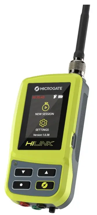 Firmware Version: 1.1.1
Manual Version: 1.0.0
HILINK GENERAL DESCRIPTION
 |  |
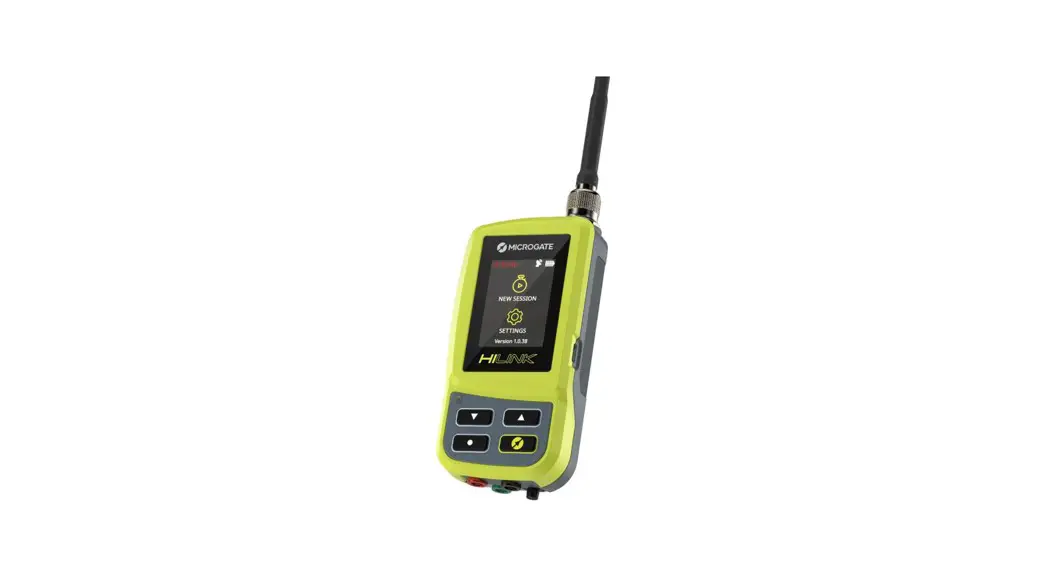
HiLink is the new Microgate radio transmission system that incorporates both the transmitter (EncRadio) and receiver (DecRadio) feature using a transceiver module operating in the 433 MHz band. The compact size (60x119x33 mm), extended temperature range (-30°C +70°C), temperature-compensated time base of ±1 ppm over the entire temperature range make it the ideal instrument for the radio transmission of timing pulses in all operating situations.
HiLink is not only a radio transmitter/receiver, but is de facto for all intents and purposes a stopwatch, being able to use both Microgate protocols and time-of-day transmission.
HiLink also has a GPS module for synchronizing the time base with the satellite signal which can turn it into a synchronizer using one of its external lines.
The narrow-band radio module can be configured via software or remotely on one of the 68 available frequencies and can be supplied in the 10 mW power version as well as in the 500 mW version.
HiLink has a Bluetooth module for communication with ReiPro and RTPro stopwatches and for receiving information about HiSmart-equipped competitors using Smart Identification protocols.
The system can also be used as a radio receiver connected by cable to all the old generation Microgate stopwatches (Rei2 and Racetime2) being fully compatible with the LinkGate EncRadio systems or as a transmitter in the presence of an old generation LinkGate DecRadio.
BASIC CHARACTERISTICS
EMBEDDED EncRadio and DecRadio functionality
| DIMENSIONS (WxHxD) | 60 x 119 x 33 mm |
| TEMPERATURE RANGE | -30°C +70°C |
| TIME BASE | temperature compensated oscillator + GPS PPS |
| TIME MEASUREMENT UNIT | selectable down to 1/10,000 sec. |
| TIME ACCURACY | 1/50,000 of a second |
| BT LE CONNECTIVITY | 433MHZ radio with 68 user selectable frequencies, 10 mW and 500 mW user selectable output power |
| INTERACTION WITH | HiSmart Tag for Smart Identification |
MANAGEMENT SOFTWARE
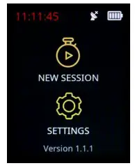
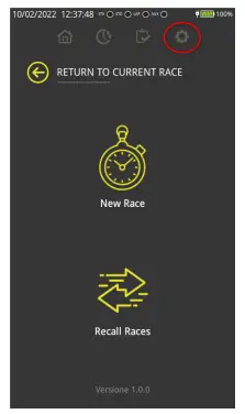
Once the system is turned on using the Microgate ON/OFF button, the home screen gives us two options:
- Start a new session
- Enter the settings menu
 2.1 NEW SESSION
The screen gives us the following information:
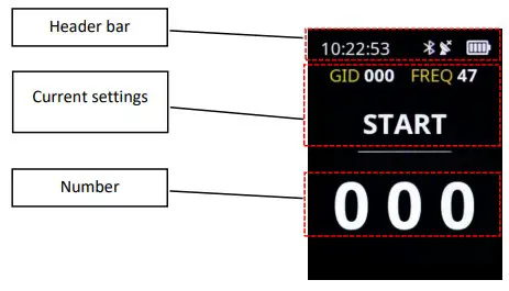
2.1.1 Header bar
The following are displayed:
- the time of day
o Red if not synchronized
o White if the system has been synchronized - the Bluetooth symbol
o Only present when connected to another device - the satellite symbol
o White if not used
o Red if enabled and a valid signal for synchronization has not yet been received
o Green if enabled and a valid synchronization signal has been received - the battery symbol with the marks for the current charge
2.1.2 Area of the currently selected settings
- GID (Group ID): represents a value that allows radio pulses to be received only from systems that have set the same Group ID. Equivalent to the old radio channel concept of the old LinkGate EncRadio systems
- FREQ: The frequency number set in transmission and reception (see table in appendix for matching frequencies and settings of old Linkgate EncRadio/DecRadio systems)
- The type of pulse being transmitted (START-STOP- LAP1…LAP14)
You can change this information in the various menus in the Settings
2.1.3 The bib number that will be transmitted
The number can be changed with the UP and DOWN arrows (press and hold to fast forward) or by touching the tens or hundreds of units for a faster change. 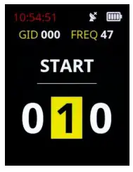
SETTINGS
In the SETTINGS menu we have 4 pages for complete system configuration. Pages are scrolled by using the Next or Back arrows highlighted on the Touch screen. 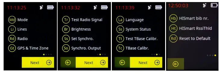
3.1 MODE
The mode describes how HiSmart devices operate and are used.
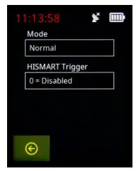
3.1.1 Method of use (Mode)
- Normal: this is the default value and means that the radio protocol used in transmission is that of the HiLink new generation
- EncRadio: if “EncRadio” mode is selected, the transmission protocol is that of the old generation of LinkGate EncRadio transmitters. In this mode HiLink can be used as a transmitter in conjunction with Rei2 and Racetime2 systems with DecRadio receivers. The “Send Device Status” (On/Off) feature can also be enabled.
- Modem: the system functions as a radio modem (for example for transmitting to a scoreboard) See Annex Connectors (pin out)
3.1.2 HiSmart Trigger
This setting allows determining at what distance HiLink will consider HiSmart devices to be in the area, and therefore the number in transmission. The possible settings are:
- 0= Disabled
- 1= Immediate Range; approximate receiving distance 20cm (used for example at the start in skiing)
- 2= Near Range; approximate receiving distance 3m
- 3= Far Range; approximate receiving distance 30m
- 2= Very Far Range; approximate receiving distance 60m
3.2 LINES
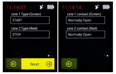
This menu makes it possible to define the type of pulse (logic channel) to be transmitted (START-STOP- LAP1…LAP14) when a signal is received on the Green (Line 1) and Red (Line 2) sockets. If the pulse is transmitted by pressing the Enter button (bottom left), the logic channel of Line 1 will be transmitted. You can also specify whether the timing line is to be configured to accept “Normally Open” or “Normally Closed” signals. The HiLink system, unlike the old EncRadio systems, allows simultaneously transmitting the two timing lines by using a new data protocol. With this perspective, for example, two starts or finishes of a parallel can be transmitted using a single transmitter or the two pulses of a speed base (which in this case will be configured as an average speed on two different laps).
3.3 RADIO
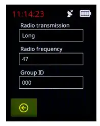
In this section we can define the parameters of the radio transmission. In particular:
3.3.1 Radio Transmission
The set parameter can take the following values:
- Long: the transmission lasts approximately 2.6 seconds and has maximum redundancy (important when the frequency is disturbed). This is the default value.
- Short: The transmission lasts approximately 0.7 seconds and has reduced redundancy. This setting is preferred when I have to closely follow multiple radio transmissions that could have the signals overlap.
3.3.2 Radio Frequency
This parameter represents the channel of the frequency used (see Appendix Radio Frequencies for matching the actual frequencies in MHz).
3.3.3 Group ID
This corresponds to the channel of the old Linkgate transmission. The receiving stopwatch must have the same number set in the “radio channel”. Group ID is generally a filter that selects radio pulses that travel on the same frequency but belong to the same Group ID. The HiLink system makes it much more convenient to change frequency when there are several people transmitting on the same radio frequency
3.4 GPS AND TIME ZONE
HiLink can be synchronized with satellite time.
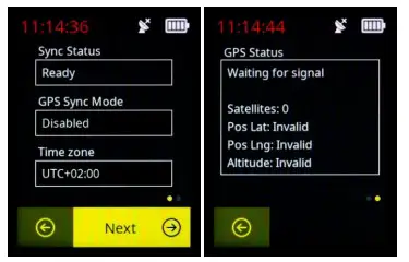
3.4.1 GPS Synchronization Mode
The synchronization of the internal time base with the satellite time base can be done in the following ways:
- Disabled: no synchronization with the satellite signal
- One Time: in this mode once the satellite signal is valid the internal base synchronizes with the satellite time and then continues with an accuracy of ±1 ppm
- Continuous: in this mode, once the satellite signal is valid, the internal base continuously synchronizes with the satellite time
3.4.2 Time Zone
The satellite synchronization time is changed taking account of the time zone compared to UTC.
3.4.3 GPS Status
This is a screen of information about satellite signal quality.
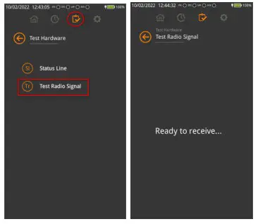
3.5 TEST RADIO SIGNAL
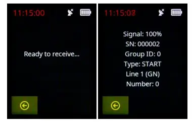
This menu allows you to check the quality of the radio signal and the transmitted information
3.6 BRIGHTNESS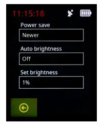
3.6.1 Battery Saver
This parameter represents the time after which the display turns off
3.6.2 Auto Brightness (ON/OFF)
HiLink has an external light sensor to automatically adjust the brightness according to the external light (parameter set to ON). If the parameter is set to OFF, the brightness is adjusted with the percentage indicated in the “Set Brightness” parameter
3.6.3 Set Brightness
In the case of Auto Brightness Off, it allows you to manually choose the brightness with values between 1 and 100%.
3.7 SET SYNCHRONIZATION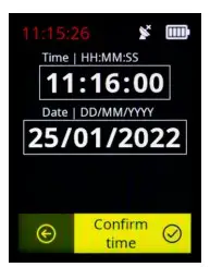
This menu allows the date and time to be set for a synchronization that can be done either manually by pressing the “Confirm time“ button on the display or via a pulse on Line 1 (green socket).
3.8 SYNCHRONIZATION OUTPUT 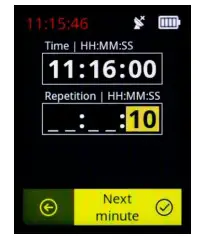 This menu is useful when we want to use HiLink as a synchronizer. By setting the time and the repetition time we will send a pulse on the green socket every repetition time starting from the indicated time. The “Next minute” button on the touch display allows you to pre-load the time of the next full minute and then define only the repetition time.
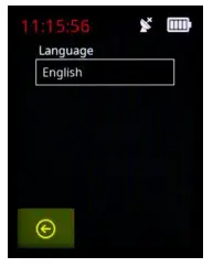
3.9 LANGUAGE
The HiLink menus can currently be displayed in Italian, English and German.
 3.10 SYSTEM STATUS
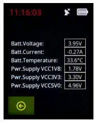 This menu allows you to check the status of system parameters such as battery voltage, current and temperature and other parameters related to the different supply voltages.
3.11 TEST TIME BASE CALIBRATION
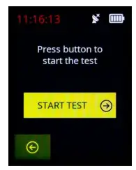
This test checks the internal time base calibration, when there is a valid GPS signal.
3.12 INTERNAL TIME BASE CALIBRATION 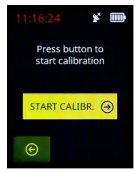
This test allows the internal time base to be calibrated, when there is a valid GPS signal.
3.13 HISMART BIB
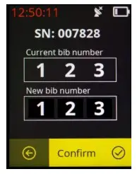
This menu allows you to detect a HiSmart device in the immediate vicinity of HiLink, showing the serial number and the current bib number. Entering a new number in the New Bib field, using the touch display and the arrows, and pressing the “Confirm” button on the display will assign the new bib number to the device.
3.14 HISMART RSSI THRESHOLD
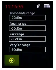
This menu allows you to assign a level of dBm of the Bluetooth signal for each detection range of the HiSmart system. The dBm value is related to the detection distance of the HiSmart systems.
3.15 RESET DEFAULT
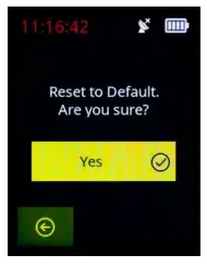
This option returns the HiLink device to the factory default settings.
BATTERY CHARGING AND OPERATING TIME
HiLink can be charged with any 5V charger with at least 500mA of power (almost all mobile phone chargers are suitable) with a USB-A to USB-C or USB-C to USB-C cable.
If the device is turned off, the status LED will light up steady AMBER when the power cord is plugged in. When charging is complete, the LED will be a steady GREEN light.
If on the contrary you want to charge the device while it is on, the external power supply symbol will appear at the top right of the display and the battery symbol will show moving bars until the battery is fully charged (all the battery bars lit steady).
Battery life is approximately 10 hours with one transmission a minute.
To perform a hardware reset, with HiLink turned on, press and hold the power button for at least 20 seconds until it turns off.
CONNECTION TO THE REIPRO AND RTPRO STOPWATCHES
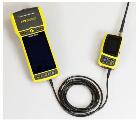
The HiLink system when used as a receiver can be connected to the ReiPro and RTPro stopwatches either by cable (use the $CAB202 cable) or directly via Bluetooth.
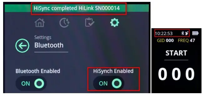
In the case of a Bluetooth connection, HiLink decodes the radio signal and sends the time of day of the received pulse to the stopwatch. The stopwatch and HiLink must be synchronized in order to obtain correct information. By default, a configuration (HiSynch Enabled=ON) is active on ReiPro and RTPro which automatically synchronizes the time base of the stopwatch with that of HiLink when connected. In this case (HiSynch parameter enabled) “HiSynch completed HiLink SN0000XX” will also be displayed.
The BT connection symbol will also appear in the status bar on the HiLink device and if synchronization is complete the colour of the time of day will be White.
If the HiSynch parameter is disabled the stopwatch will receive the information only if both the stopwatch and HiLink are synchronized either by cable or via satellite signal.
5.1 RTPRO-HILINK CONNECTION VIA BLUETOOTH
In the case of a Bluetooth connection, the first time (after which you no longer need to do this) HiLink must be connected to the RTPro stopwatch by following the steps below:
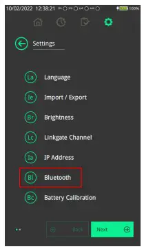
- From the RTPro main screen, click on the settings icon

- Select the Bluetooth menu

- Make sure that the HiLink you want to use as a receiver is turned on.
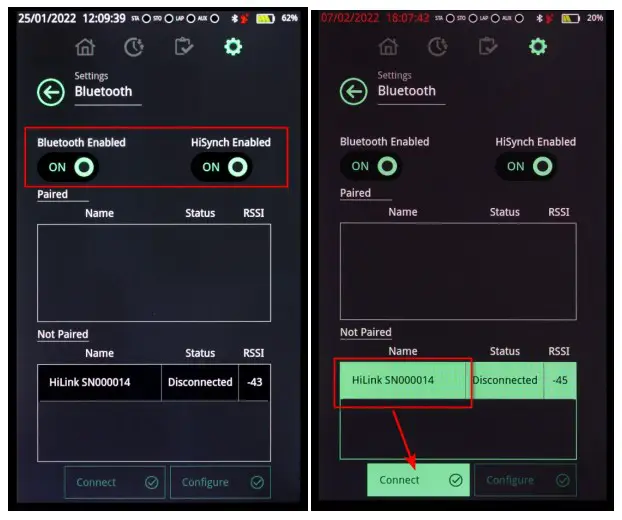
- Verify that the Bluetooth and HiSynch functions on RTPRO are enabled
- Select that device from the list of available devices and press connect.

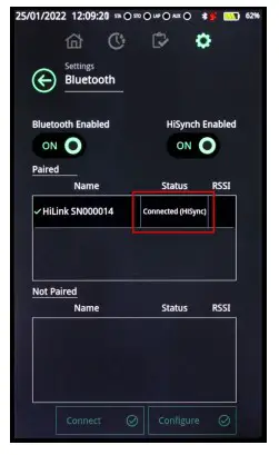
- Wait until the device status is “Connected(HiSynch)”

RTPRO AND HILINK USAGE CONFIGURATIONS
The RTPro stopwatch together with the HiLink radio system can be used in several ways, and the Hilink system is fully compatible with previous generation Linkgate systems (Encoder and Decoder).
First of all, it is important to note that there are two ways to connect HiLink to RTPro:
- By Cable using the specific cable ($CAB202)

- Via Bluetooth using the procedure described earlier in the chapter 5.1
Let us now see how, by using one of these connection methods, the following operating modes can be established.
6.1 FREE RTPRO AND HILINK ALONG THE ROUTE
The steps to follow are as follows:
6.1.1 The connection to the stopwatch by cable
Connect HiLink to the RTPro stopwatch.
If you connect HiLink by cable, no configuration needs to be done on the device
6.1.2 The connection to the stopwatch via Bluetooth
See chapter 5.1 for the sequence of operations.
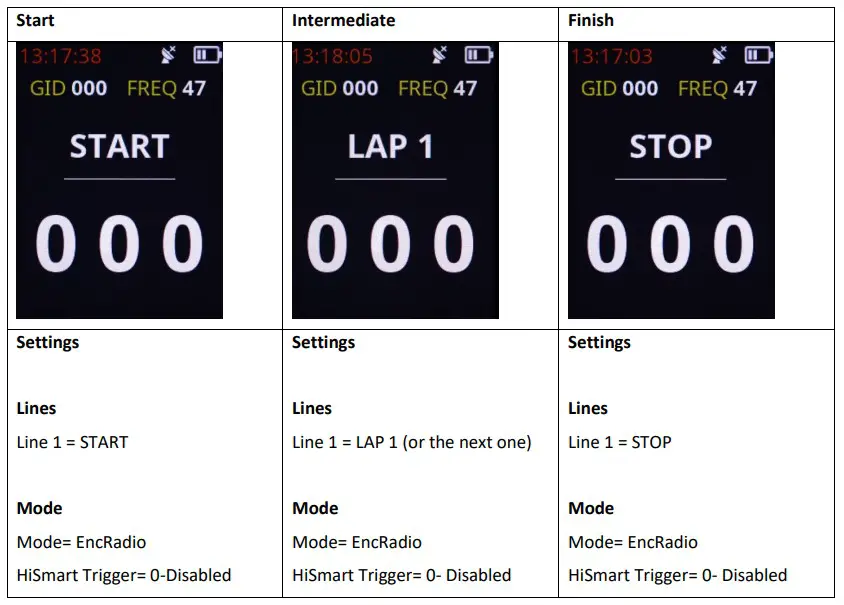
6.1.3 The setting of the transmission devices
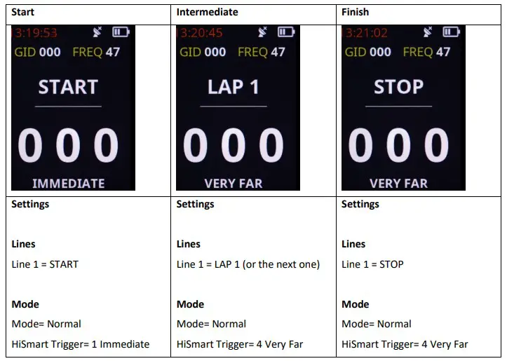
Depending on the function, the HiLink devices should be configured as follows:
You should also check that all the HiLink devices are set to the same GroupID and on the same transmission frequency. See subsection Error! Reference source not found. for configuring these parameters.
It is recommended to perform a successful transmit-receive check using the RTPro “Test Hardware” and “Test Radio Signal” menu.
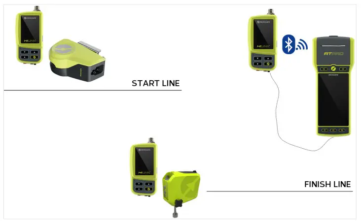
6.2 RTPRO AND HILINK WITH CONNECTION AT START OR FINISH
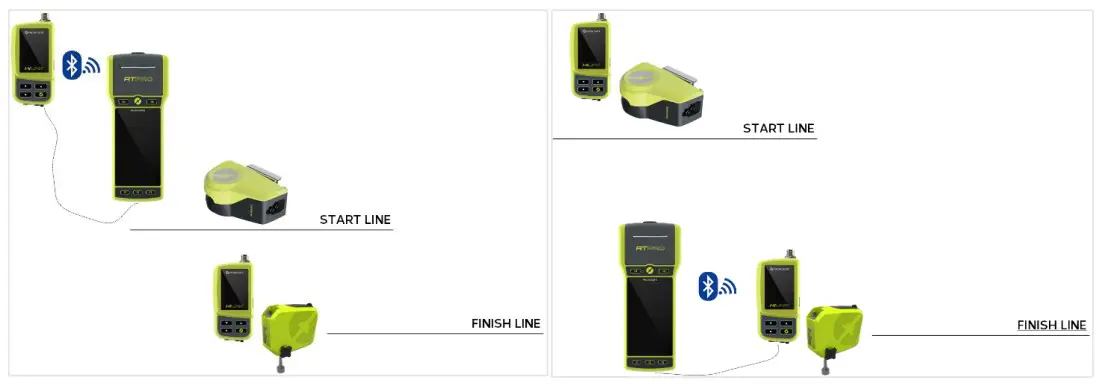
In this situation the RTPro stopwatch can be connected by cable or via BT directly to the HiLink device at the start or finish using the methods described in the previous parameter. In the case of connection via BT, the stopwatch must remain at a communication distance supported by BT technology (approximately less than 50m).
6.3 RTPRO AND HILINK USED IN CONJUNCTION WITH ENCRADIO MF TRANSMITTERS
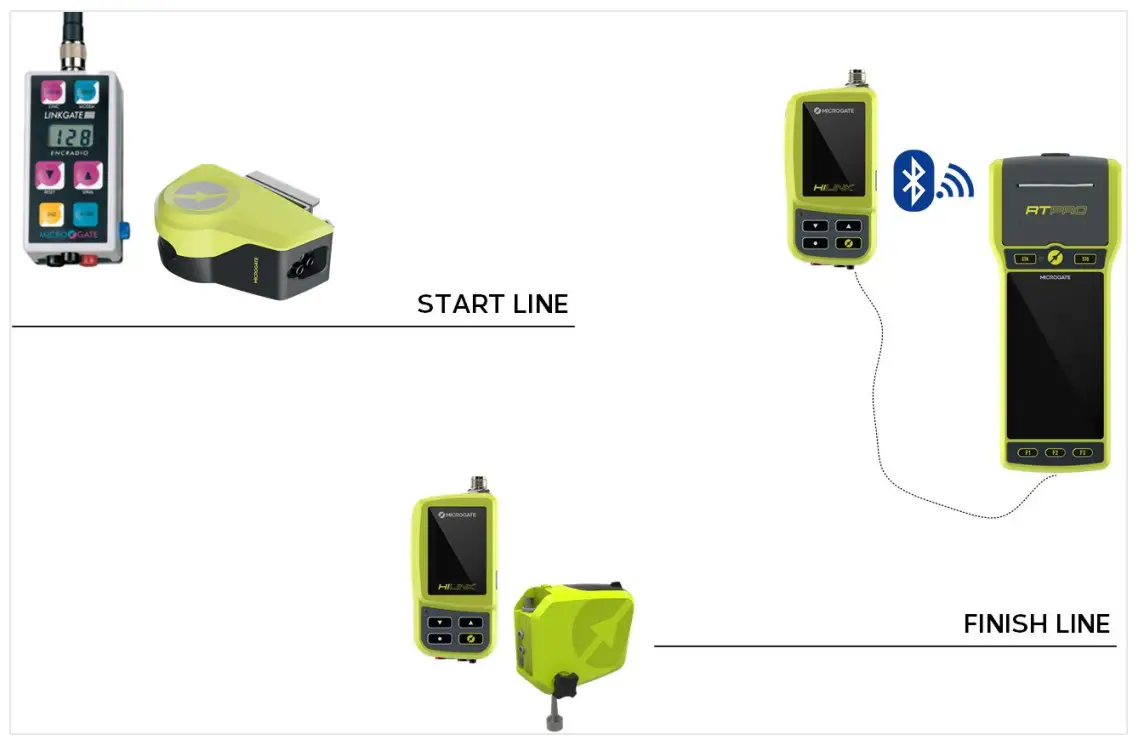
The HiLink system fully interfaces with the old EncRadio MF 10mW and 500mW transmitters without any need for specific configurations. However, the following parameters must be taken into account:
- The transmission frequency of the EncRadio devices must be the same as that selected on the HiLink devices. The compatibility table is as follows:
Center Frequency [MHz]
HIFamily
[FREQ
Number]LinkGate Radio (multi-frequency)
[DIP SWITCH]Switch 1 Switch 2 Switch 3 Switch 4
433.9000 33 ON ON ON ON 433.9500 35 OFF ON ON ON 434.0000 37 ON OFF ON ON 434.0500 39 OFF OFF ON ON 434.1000 41 ON ON OFF ON 434.1500 43 OFF ON OFF ON 434.2000 45 ON OFF OFF ON 434.2500 47 OFF OFF OFF ON 434.3000 49 ON ON ON OFF 434.3500 51 OFF ON ON OFF 434.4000 53 ON OFF ON OFF 434.4500 55 OFF OFF ON OFF 434.5000 57 ON ON OFF OFF 434.5500 59 OFF ON OFF OFF 434.6000 61 ON OFF OFF OFF 434.6500 63 OFF OFF OFF OFF The default HiLink frequency is the default frequency of the EncRadio systems.
- The Radio Channel of the EncRadio devices used must match the GroupID of the HiLink system.
6.4 RTPRO AND HILINK USED IN CONJUNCTION WITH ENCRADIO SF AND POLIFEMO RADIO SF TRANSMITTERS
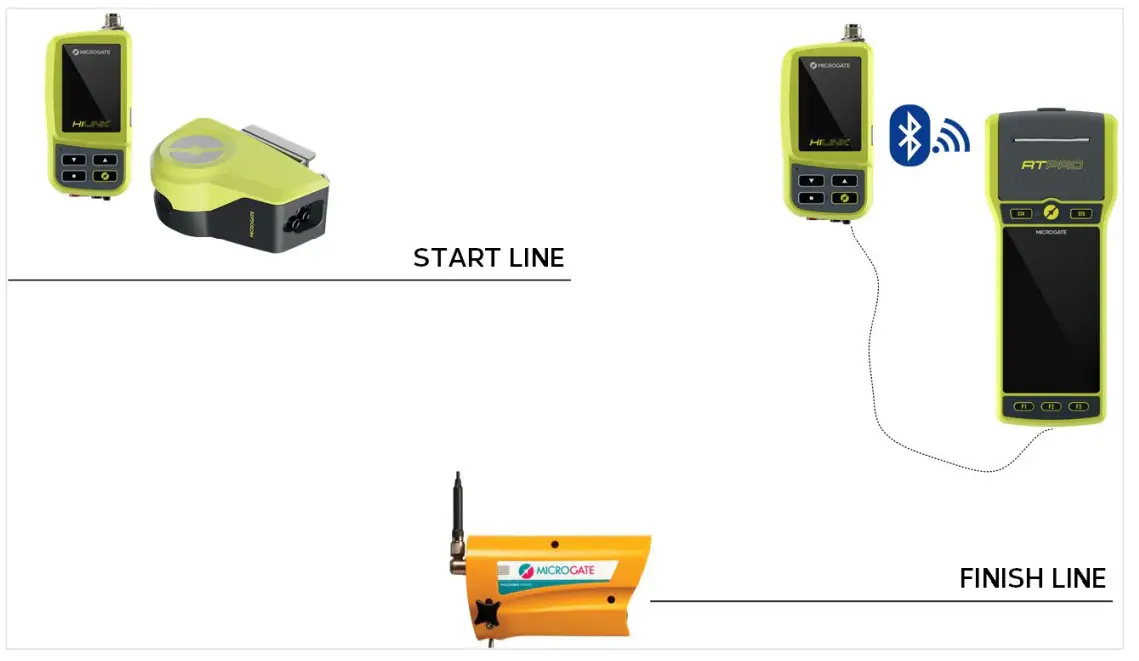
The HiLink system fully interfaces with the old EncRadio SF 10mW and 500mW transmitters and with the Polifemo SF photocells without any need for specific configurations. However, the following parameters must be taken into account:
- The transmission frequency of the HiLink devices must be set to the following values:
Center Frequency
[MHz]HIFamily
[FREQ Number]Linkgate Radio SF/SF2/SF3/SF4 (single frequency) SF SF2 SF3 SF4
433.9200 Not compatible * 434.0750 40 * 434.6000 61 * 434.7000 65 * - The Radio Channel of the EncRadio devices used must match the GroupID of the HiLink system.
6.5 RACETIME 2 AND HILINK USED AS TRANSMITTER
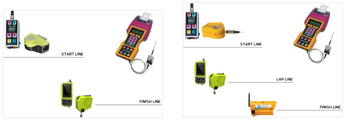
If you have a Racetime2 stopwatch with a Linkgate MF or SF transmission system, you can always integrate it with new HiLink transmitters.
HiLink transmitters must be configured as follows:
 The following parameters must then be taken into account:
- The transmission frequency of the HiLink devices must be set to the following values:
In the case of SF systemsCenter Frequency
[MHz]HIFamily
[FREQ Number]Linkgate Radio SF/SF2/SF3/SF4 (single frequency)
SF SF2 SF3 SF4
433.9200 Not compatible * 434.0750 40 * 434.6000 61 * 434.7000 65 * In the case of MF systems
Center Frequency
[MHz]HIFamily
[FREQ
Number]LinkGate Radio (multi-frequency)
[DIP SWITCH]Switch 1 Switch 2 Switch 3 Switch 4
433.9000 33 ON ON ON ON 433.9500 35 OFF ON ON ON 434.0000 37 ON OFF ON ON 434.0500 39 OFF OFF ON ON 434.1000 41 ON ON OFF ON 434.1500 43 OFF ON OFF ON 434.2000 45 ON OFF OFF ON 434.2500 47 OFF OFF OFF ON 434.3000 49 ON ON ON OFF 434.3500 51 OFF ON ON OFF 434.4000 53 ON OFF ON OFF 434.4500 55 OFF OFF ON OFF 434.5000 57 ON ON OFF OFF 434.5500 59 OFF ON OFF OFF 434.6000 61 ON OFF OFF OFF 434.6500 63 OFF OFF OFF OFF - The Radio Channel of the EncRadio devices used must match the GroupID of the HiLink system.
6.6 RACETIME 2 AND HILINK USED AS RECEIVER VIA CABLE
The HiLink system can also be used as a radio receiver for the cable-connected Racetime2 stopwatch.
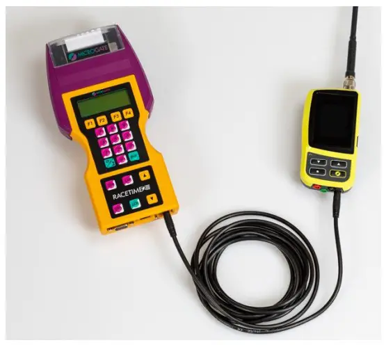
In this case the HiLink system does not need any configuration.
The following parameters must then be taken into account:
2. The reception frequency of the HiLink device must be set to the following values:
In the case of SF transmission systems
Center Frequency | HIFamily [FREQ Number] | Linkgate Radio SF/SF2/SF3/SF4 (single frequency) | |||
| SF | SF2 | SF3 | SF4 | ||
| 433.9200 | Not compatible | * | |||
| 434.0750 | 40 | * | |||
| 434.6000 | 61 | * | |||
| 434.7000 | 65 | * | |||
In the case of MF transmission systems
Center Frequency | HIFamily [FREQ Number] | LinkGate Radio (multi-frequency) [DIP SWITCH] | |||
| Switch 1 | Switch 2 | Switch 3 | Switch 4 | ||
| 433.9000 | 33 | ON | ON | ON | ON |
| 433.9500 | 35 | OFF | ON | ON | ON |
| 434.0000 | 37 | ON | OFF | ON | ON |
| 434.0500 | 39 | OFF | OFF | ON | ON |
| 434.1000 | 41 | ON | ON | OFF | ON |
| 434.1500 | 43 | OFF | ON | OFF | ON |
| 434.2000 | 45 | ON | OFF | OFF | ON |
| 434.2500 | 47 | OFF | OFF | OFF | ON |
| 434.3000 | 49 | ON | ON | ON | OFF |
| 434.3500 | 51 | OFF | ON | ON | OFF |
| 434.4000 | 53 | ON | OFF | ON | OFF |
| 434.4500 | 55 | OFF | OFF | ON | OFF |
| 434.5000 | 57 | ON | ON | OFF | OFF |
| 434.5500 | 59 | OFF | ON | OFF | OFF |
| 434.6000 | 61 | ON | OFF | OFF | OFF |
| 434.6500 | 63 | OFF | OFF | OFF | OFF |
3. The Radio Channel of the EncRadio devices used must match the GroupID of the HiLink system.
HISMART THE AUTOMATIC SYSTEM FOR THE RECOGNITION OF ATHLETES
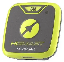 The HiSmart device is an integrated tag in the HiLink system designed for automatic recognition of athletes. HiSmart uses a Bluetooth protocol that allows the start, intermediate and finish HiLink to be sent the bib number of the athlete who will pass through that point. The device is supplied with a preset bib number that can be read in the top window and can be changed by HiLink (see HiSmart bib change menu) or by the ProUpdater program that can be downloaded from the Microgate website.
 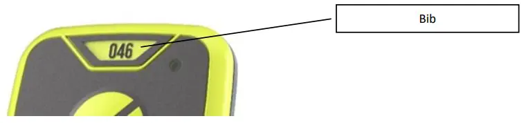 The HiLink system allows you to configure the distance at which HiSmart will be detected.
This setting allows determining at what distance HiLink will consider HiSmart devices to be in the area, and therefore the number in transmission. The possible settings are:
- 0= Disabled
- 1= Immediate Area; approximate receiving distance 20cm (used for example at the start in skiing)
- 2= Near Area; approximate receiving distance 3m
- 3= Far Area; approximate receiving distance 30m
- 2= Very Far Area; approximate receiving distance 60m
The recommended basic configurations are as follows: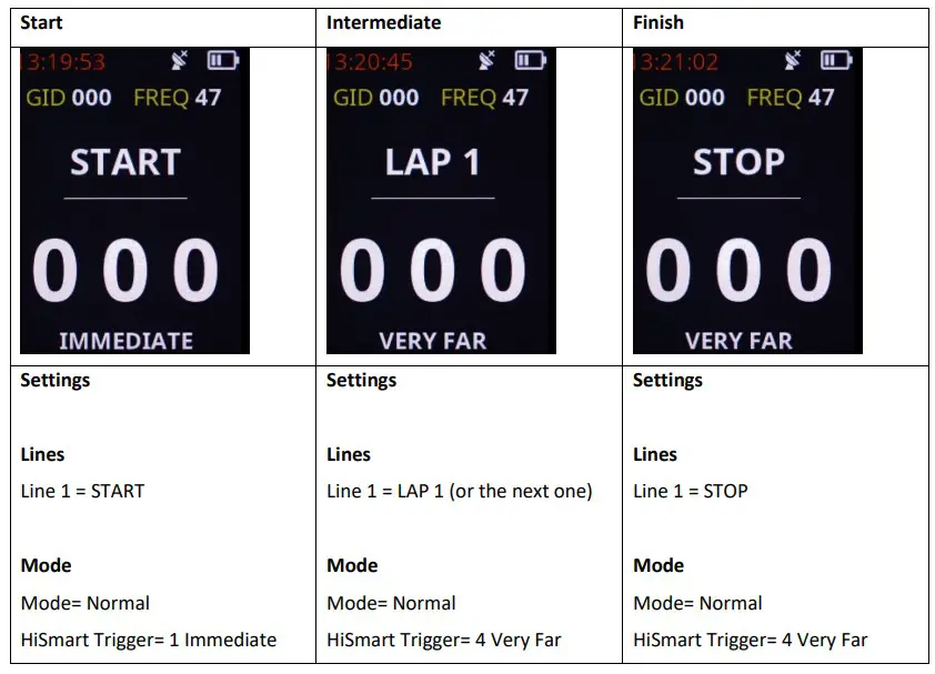 This setting allows determining at what distance HiLink will consider HiSmart devices to be in the area, and therefore the number in transmission. The possible settings are:
- 0= Disabled
- 1= Immediate Area; approximate receiving distance 20cm (used for example at the start in skiing)
- 2= Near Area; approximate receiving distance 3m
- 3= Far Area; approximate receiving distance 30m
- 2= Very Far Area; approximate receiving distance 60m
On the RTPro stopwatch, for the “Training Light” program, it is also possible to configure a parameter which, during timing, only filters the times of HiSmart owners detected by HiLink. In “Settings”- “RTPro Settings”- “Software Configuration” the parameter “HiSmart Filter”, if selected, enables this feature.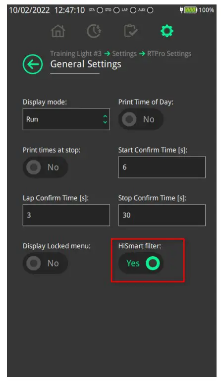 7.1 SWITCHING ON AND OFF
HiSmart is switched on by pressing and holding the middle button (Microgate symbol) for longer than 3 seconds. Once on, the status LED blinks slowly with a GREEN light. If the button is held down for less than 3 seconds, the RED LED (error signal) is shown for 3 seconds and the device remains off. This feature is designed to prevent the device from being turned on accidentally by briefly pressing the button.
To switch off, you need to press and hold the middle button for longer than 3 seconds and then the status LED will turn RED. At that time, on releasing the button, the device will switch off.
7.2 CHARGING HISMART
HiSmart is charged with any 5V charger with at least 100mA of power with a USB socket and a USB-A to USBC or USB-C to USB-C cable or with an inductive charger (any mobile charger is suitable). Once set charging, the status LED will light up steady AMBER. When HiSmart is fully charged (full charging takes approximately 2 hours) the light is steady GREEN. If the status LED slowly blinks RED after the device is turned on, the device is in Low Battery status.
7.3 BATTERY LIFE
With a full charge, HiSmart will run for more than 14 hours. Once low battery has been signalled, the device still has 2 hours of battery life.
7.4 SLEEP MODE AND HARDWARE RESET
To perform a HiSmart Hardware reset, with the device turned on, press and hold the middle button until the status LED, which has turned RED, switches completely off. After doing this, HiSmart goes into a Sleep mode with very low power consumption (10nA) that preserves the battery.
On the contrary, switching the device off normally will deplete the batteries (if not used) in approximately 2 months.
ANNEX CONNECTORS (PIN OUT)
All connectors are viewed from the contact side (as seen when looking at the HILINK from the front). The connection diagrams are provided for documentation purposes. Microgate recommends using its original cables, which are EC approved.
Female connector, Binder 5-pole 240°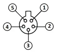 8.1 CHRONOMETER
Female connector, Binder 5-pole 240°
- RS232 serial output (TXD)
- Not connected
- RS232 serial input (RXD)
- Not connected
- Ground
APPENDIX RADIO FREQUENCIES
9.1 HIFAMILY RADIO FREQUENCY TABLE – 434 MHZ BAND
Center Frequency [MHz] | HIFamily [FREQ Number] |
| 433.0750 | 0 |
| 433.1000 | 1 |
| 433.1250 | 2 |
| 433.1500 | 3 |
| 433.1750 | 4 |
| 433.2000 | 5 |
| 433.2250 | 6 |
| 433.2500 | 7 |
| 433.2750 | 8 |
| 433.3000 | 9 |
| 433.3250 | 10 |
| 433.3500 | 11 |
| 433.3750 | 12 |
| 433.4000 | 13 |
| 433.4250 | 14 |
| 433.4500 | 15 |
| 433.4750 | 16 |
| 433.5000 | 17 |
| 433.5250 | 18 |
| 433.5500 | 19 |
| 433.5750 | 20 |
| 433.6000 | 21 |
| 433.6250 | 22 |
| 433.6500 | 23 |
| 433.6750 | 24 |
| 433.7000 | 25 |
| 433.7250 | 26 |
| 433.7500 | 27 |
| 433.7750 | 28 |
| 433.8000 | 29 |
| 433.8250 | 30 |
| 433.8500 | 31 |
| 433.8750 | 32 |
| 433.9000 | 33 |
| 433.9250 | 34 |
| 433.9500 | 35 |
| 433.9750 | 36 |
| 434.0000 | 37 |
| 434.0250 | 38 |
| 434.0500 | 39 |
| 434.0750 | 40 |
| 434.1000 | 41 |
| 434.1250 | 42 |
| 434.1500 | 43 |
| 434.1750 | 44 |
| 434.2000 | 45 |
| 434.2250 | 46 |
| 434.2500 | 47 |
| 434.2750 | 48 |
| 434.3000 | 49 |
| 434.3250 | 50 |
| 434.3500 | 51 |
| 434.3750 | 52 |
| 434.4000 | 53 |
| 434.4250 | 54 |
| 434.4500 | 55 |
| 434.4750 | 56 |
| 434.5000 | 57 |
| 434.5250 | 58 |
| 434.5500 | 59 |
| 434.5750 | 60 |
| 434.6000 | 61 |
| 434.6250 | 62 |
| 434.6500 | 63 |
| 434.6750 | 64 |
| 434.7000 | 65 |
| 434.7250 | 66 |
| 434.7500 | 67 |
| 434.7750 | 68 |
9.2 LINKGATE RADIO MF COMPATIBLE RADIO FREQUENCY TABLE – 434 MHZ BAND
Center Frequency [MHz] | HIFamily [FREQ Number] | LinkGate Radio (multi-frequency) [DIP SWITCH] | |||
| Switch 1 | Switch 2 | Switch 3 | Switch 4 | ||
| 433.9000 | 33 | ON | ON | ON | ON |
| 433.9500 | 35 | OFF | ON | ON | ON |
| 434.0000 | 37 | ON | OFF | ON | ON |
| 434.0500 | 39 | OFF | OFF | ON | ON |
| 434.1000 | 41 | ON | ON | OFF | ON |
| 434.1500 | 43 | OFF | ON | OFF | ON |
| 434.2000 | 45 | ON | OFF | OFF | ON |
| 434.2500 | 47 | OFF | OFF | OFF | ON |
| 434.3000 | 49 | ON | ON | ON | OFF |
| 434.3500 | 51 | OFF | ON | ON | OFF |
| 434.4000 | 53 | ON | OFF | ON | OFF |
| 434.4500 | 55 | OFF | OFF | ON | OFF |
| 434.5000 | 57 | ON | ON | OFF | OFF |
| 434.5500 | 59 | OFF | ON | OFF | OFF |
| 434.6000 | 61 | ON | OFF | OFF | OFF |
| 434.6500 | 63 | OFF | OFF | OFF | OFF |
9.3 LINKGATE RADIO SF COMPATIBLE RADIO FREQUENCY TABLE – 434 MHZ BAND
| Center Frequency [MHz] | HIFamily [FREQ Number] | Linkgate Radio SF/SF2/SF3/SF4 (single frequency) | |||
| SF | SF2 | SF3 | SF4 | ||
| 433.9200 | Not compatible | * | |||
| 434.0750 | 40 | * | |||
| 434.6000 | 61 | * | |||
| 434.7000 | 65 | * | |||
![]() Issue Date: 05/02/2022
Issue Date: 05/02/2022


