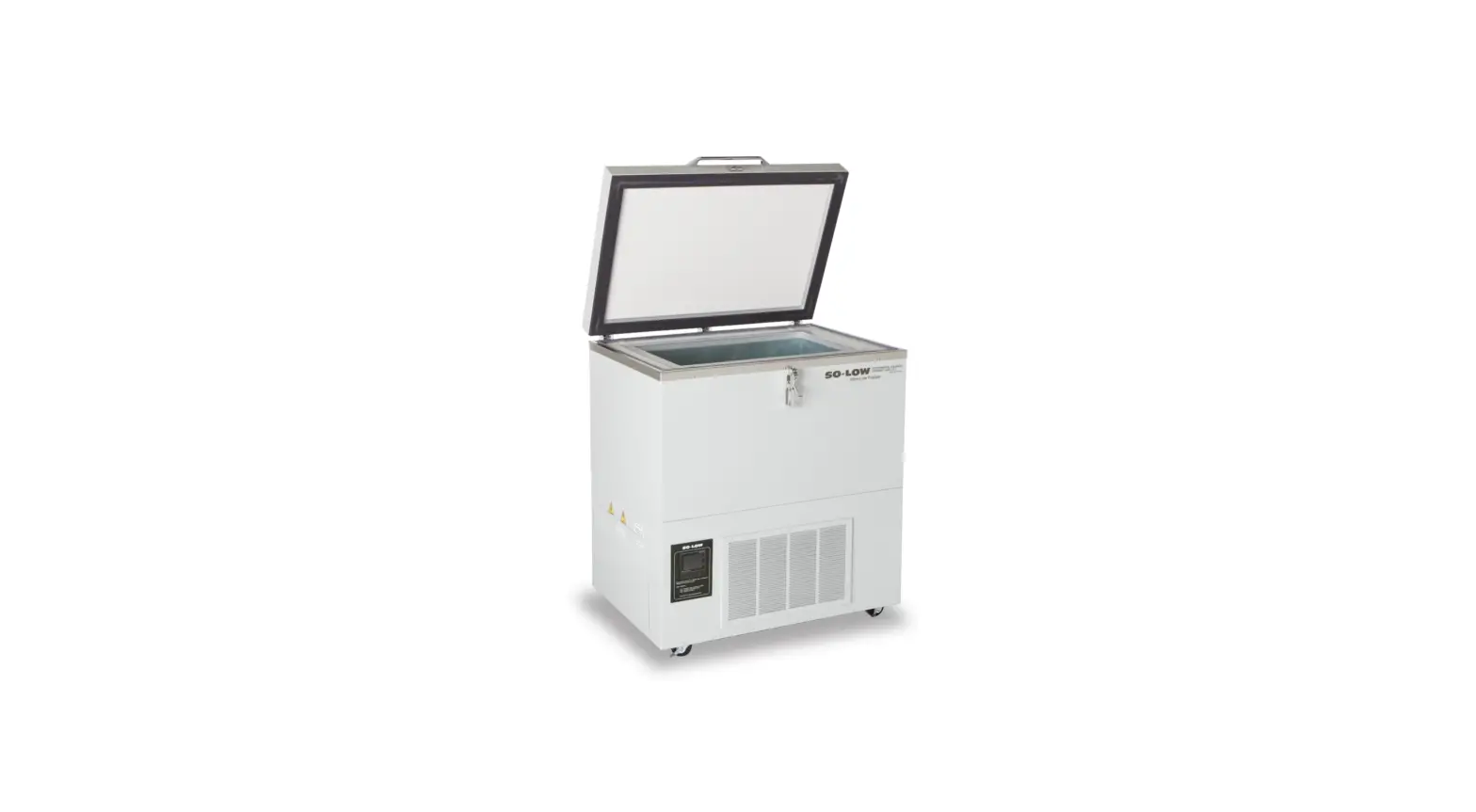
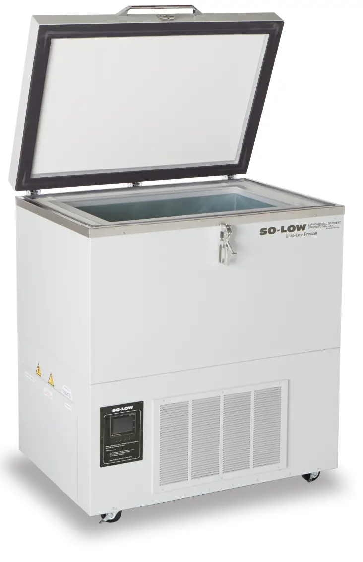
So-Low Environmental Equipment Co Inc CH 4000 Chest Freezer
Product Information
The chest freezer is an electronic device that is used to store and preserve food items at a low temperature. The freezer is equipped with a compressor that regulates the temperature and maintains the desired temperature set by the user. The temperature control is an electronic control panel with two displays, one for the actual temperature and the other for the temperature set point. The freezer is also equipped with an alarm system that automatically activates when it reaches the set point or after 8 hours of being plugged in. The alarm can also be manually activated by moving the toggle switch to the on position. The freezer is provided with an input circuit protective device that should only be maintained and serviced by qualified personnel.
Starting Instructions
- Plug the freezer into the proper outlet with an adequate power supply.
- Confirm the freezer has at least 6 inches of air space on each side for air circulation.
- The compressor will start to operate and pull down to the set point on the temperature control.
- When the freezer reaches the set point, the compressor will cycle on and off to maintain the desired temperature set by the user on the temperature control.
CAUTION!
Unplug the freezer before any technical service is performed on the unit. Do not position equipment so it is difficult to disconnect from the power supply.
Usage Instruction
Cleaning Procedure
- Wipe down the exterior of the freezer with a soft cloth and spray-type polish.
- If frost builds up in the chamber, a bucket and ice-scraper can be used to remove the ice. If excessive ice builds up, the unit can be defrosted (see below).
Defrost Procedure
- Remove any product in the freezer and store it in a backup freezer or elsewhere.
- Unplug the freezer and open the front door or lid.
WARNING!
Unauthorized entry into the temperature control will void the warranty. Use only the up and down keys when making changes on this control. Contact the factory for all other adjustments in settings.
Alarm Battery Testing
If applicable, the alarm switch has a test position that can be used anytime to see if the battery is charged or if the buzzer is working properly.
CAUTION!
Non-rechargeable batteries should be changed approximately every two years. Rechargeable batteries should be changed approximately every three years with lead-acid rechargeable 1.2 Ah min, model PS-640F1 or equivalent.
WARNING!
The alarm relay contact connection rating for PARTLOW 1160 is 10A 250VAC, for FDC 4100 is 10A 250VAC, and for FDC 4000 is 2A 125 VAC and 10A 30VDC.
STARTING INSTRUCTIONS
- Plug the freezer into the proper outlet with an adequate power supply.
- Confirm the freezer has at least 6” of air space on each side, for air circulation.
- The compressor will start to operate and pull down to the set point on the temperature control.
- When the freezer reaches the set point, the compressor will cycle on and off to maintain the set point desired by the user on the temperature control.
- CAUTION! THIS FREEZER IS PROVIDED WITH AN INPUT CIRCUIT PROTECTIVE DEVICE WHICH SHALL BE MAINTAINED AND SERVICED BY QUALIFIED PERSONNEL ONLY. FUSES OR BREAKERS USED INSIDE PROTECTIVE DEVICE 15A OR 20A 250V TIME DELAY
- WARNING! UPLUG FREEZER BEFORE ANY TECHNICAL SERVICE IS PREFORMED ON THE UNIT!
- CAUTION! DO NOT POSITION EQUIPMENT SO IT IS DIFFICULT TO DISCONNECT FROM THE POWER SUPPLY.
CLEANING PROCEDURE
- Wipe down the exterior of the freezer with a soft cloth and spray type polish.
- If frost builds up in the chamber, a bucket and ice-scraper can be used to the ice. If excessive ice builds up, the unit can be defrosted (see below).
DEFROST PROCEDURE
- Remove any product in the freezer and store it in a back-up freezer or elsewhere.
- Unplug the freezer, and open the freezer front door / lid. For upright units, use a cloth to protect the control from dripping water.
- Air out the freezer for at least 12 hours, allowing the unit to reach room temperature.
- Take a rag and wipe up all the excess water in the unit (melted frost).
- Plug the unit in and set your temperature to the desired setpoint
- Once the desired temperature is reached, add product back into the unit.
NOTE:
It is recommended to slowly re-add your product into the freezer to prevent an extreme load on the compressors, which could shorten freezer life expectancy.
WARNING SYMBOLS
| BLACK WITH YELLOW BACKGROUND | LIGHTNING BOLT | CAUTION: RISK OF ELECTRICAL SHOCK |
| BLACK WITH YELLOW BACKGROUND | EXCLIMATION POINT | CAUTION: REFER TO ACCOMPANYING DOCUMENTS |
TEMPERATURE CONTROL
The temperature control is manually adjustable to the desired temperature in 1° C increments within the limits of the control range.
WARNING
Unauthorized entry into this control will void warranty.
PARTLOW NO. 1160, FDC 4100, FDC 4000 ELECTRONIC CONTROL
NOTE:
USE ONLY THE “UP” AND “DOWN” KEYS![]() WHEN MAKING CHANGES ON THIS CONTROL. WARRANTY WILL BE VOID IF USED IN ANY OTHER WAY. CONTACT FACTORY FOR ALL OTHER ADJUSTMENTS IN SETTINGS.
WHEN MAKING CHANGES ON THIS CONTROL. WARRANTY WILL BE VOID IF USED IN ANY OTHER WAY. CONTACT FACTORY FOR ALL OTHER ADJUSTMENTS IN SETTINGS.
TEMPERATURE SET POINT:
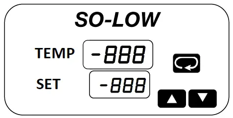
The control has two displays, the upper display is the actual chamber temperature and the lower display is the temperature set point. The temperature set point has been preset at the factory.
CHANGING TEMPERATURE SET POINT:
The temperature set point can be changed by simply pressing the “up” arrow to raise or the “down” arrow to lower the temperature set point.
ALARM SYSTEM
| MODEL | OPERATION INSTRUCTIONS |
| FDC 4000 | Alarm will automatically activate when the freezer reaches set point or 8 hours after the unit has been first plugged in. |
| FDC 4100 | Manually activate the alarm by moving the toggle switch to the on position once the freezer reaches setpoint. |
| PARTLOW 1160 | Manually activate the alarm by moving the toggle switch to the on position once the freezer reaches setpoint. |
The alarm will not sound again until the temperature varies 12°C (20°F) from the temperature control set point. Please note that the alarm will sound if there is a power outage to the freezer.
Alarm system should be tested every 30 days.
- Non-rechargeable batteries should be changed approximately every two years.
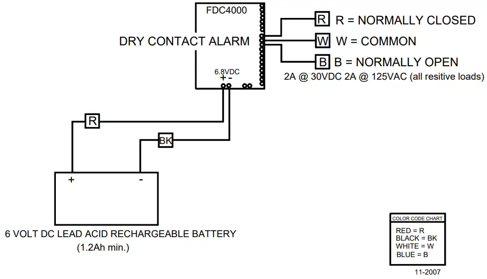
- Rechargeable batteries should be changed approximately every three years with lead acid rechargeable 1.2 Ah min, model PS-640F1 or equivalent.
ALARM BATTERY TESTING
If applicable, the alarm switch has a test position that can be used anytime to see if the battery is charged or if the buzzer is working properly.
OPTIONAL EQUIPMENT – DRY CONTACT ALARM RELAY
Located on the back of the freezer is a terminal strip marked ALARM RELAY CONTACTS. Rating of this connection:
| ALARM RELAY CONTACTS CONNECTION RATING | ||
| PARTLOW 1160 | FDC 4100 | FDC 4000 |
| 10A 250VAC | 10A 250VAC | 2A 125 VAC |
| 10A 30VDC | 10A 30VDC | 2A 30 VDC |
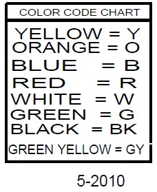
- RED – NORMALLY CLOSED
- WHITE – COMMON
- BLUE – NORMALLY OPEN
CAUTION!
IF IT IS NECESSARY TO REMOVE METAL COVER SCREEN ON BACK OF FREEZER TO MAKE CONNECTIONS TO ALARM RELAY, COVER MUST BE REPLACED BEFORE FREEZER IS PUT INTO OPERATION
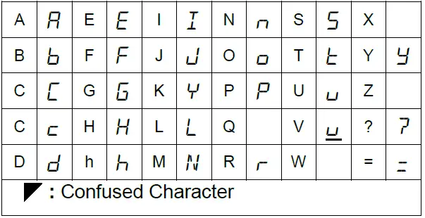
Keys and Displays
The FDC-4000 controller is programmed by using three keys on the front panel. The available key functions are listed in following table. Note: Only use the tip of your finger to depress the keys. Using a rigid object such as a pen, screwdriver or even your finger-nail may permanently damage the keypad.
| TOUCH KEYS | FUNCTION | DESCRIPTION |
| Up Key | Press and release to increase the control set-point (while in normal control mode) or to change lower display program parameter (while in User Menu or Factory Mode). Press and hold to accelerate increment speed. | |
| Down Key | Press and release to decrease the control set-point (while in normal control mode) or to change lower display program parameter (while in User Menu or Factory Mode). Press and hold to accelerate decrement speed. | |
| Pressing key while in normal control mode |
Scroll Key | Press and hold for at least 2 seconds and release (while in normal control mode) to access operator level parameters. Press and release to cycle through all user parameters. Press and hold for 2 seconds and release to silence audible alarm under normal power or on battery power. While unit is in an alarm condition, the external alarm relay contacts will remain energized until the alarm condition no longer exists. Press and hold to display chamber temperature while the controller is on battery power. Chamber temperature will be displayed until key is released. Alarm contact will remain energized while operating on battery power. |
| Press both keys simultaneously
| Current Power Reading | Displays current AC power (i.e. 110VAC) as long as keys are pressed. If power is 110VAC or 220VAC, unit will display 110. Mode is only active during normal control mode (when top display = PV, Lower display = SP). N/A on battery power. |
| Press both keys simultaneously
| Alarm Test | Energize audible alarm and alarm relay output as long as keys are pressed. Mode is only active during normal control mode (when top display = PV, Lower display = SP). N/A on battery power. |
Note:
When the controller is displaying temperature in normal control mode, press/release or press/hold the up/down keys to change the set-point value. This set-point mode does not apply to power off modes.
The upper display is used to show the process value or menu prompt. The lower display is used to show the set-point value or menu value. Both displays are blank while on battery power unless the![]() button is pressed to display the process value. Note: When operating on battery power, the battery status LED (labeled “BAT” on the front panel) will be lit.
button is pressed to display the process value. Note: When operating on battery power, the battery status LED (labeled “BAT” on the front panel) will be lit.
Table 4.1 Common Failure Causes and Corrective Actions
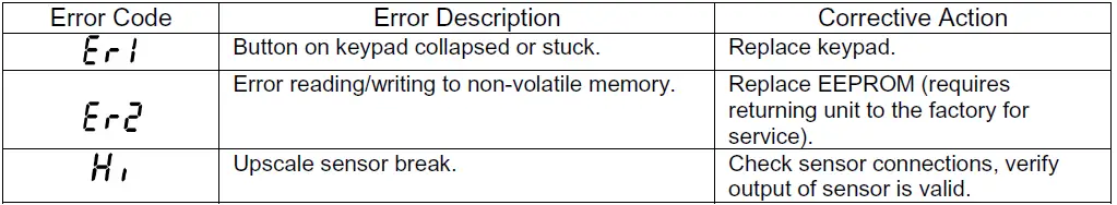
Table 4.2 Error Codes and Corrective Actions
Controller Specifications
Power Requirements
- Main: 12VAC (420mA), 5VA Max.
- Battery Back-up: 6 VDC (Lead Acid Re-chargeable, 1.2Ah min.)
- Battery Charge Current: < 400mA
Accuracy
- +/- 1 Digit
Input #1
Type “T” Thermocouple or
Platinum 100 Ohm RTD (0.00385 Ohms/Ohm/ºC)
Input #2
Type “T” Thermocouple
| Input Type | PT.100 | Type “T” TC |
| Range Low | -230 ºC (-382 ºF) | -250 ºC (-418 ºF) |
| Range High | 400 ºC (752 ºF) | 300 ºC (572 ºF) |
Table 5.1 Input Ranges
Sensor Break Detection
Sensor open for TC or RTD
Sensor Break Response Time
< 4 seconds for TC or RTD
Control Mode
- Control Output: Direct (Cooling) On/Off with adjustable set-point and hysteresis.
- Alarm Output: Programmable Deadband with adjustable hysteresis.
Control and Alarm Output
DPDT Relay, 2A @ 30 VDC, 2A @ 125 VAC, 1A @ 230VAC (all resistive loads)
User Interface
Dual 4-Digit LED Displays:
- Upper Display 0.55” (14mm)
- Lower Display 0.40” (10mm)
- Keypad (3 touch keys)
Overall Dimensions
- 6-1/4” x 8-1/2” 158.7(5mm x 215.90mm)
Environmental
- Operating Temp: 0 to +60ºC
- Storage Temp: -40 to +60º
- Humidity: 0 to 90% RH (non-condensing)
Approvals
- UL / CUL / CE Pending
Backup Battery Life
70 hours using 6VDC, 1.2A rechargeable battery
TO ENTER THE USER PARAMETER MODE
- To enter; hold scroll key
 for 2 seconds and release.
 - To exit; press and release the Scroll Button.
- Use the
 or
or arrow keys to make your changes.
TO ENTER THE PROGRAM PARAMETER MODE
- To enter; hold scroll key until screen changes to ‘SPL’, then release (about 15 seconds).
- To page through Parameters; Press and Release the scroll key.
- Please read the superscript instructions (bottom of page) for each Parameter value.
THE FOLLOWING VALUES WERE SET WHEN THIS UNIT WAS SHIPPED
| PARAMETERS | DESCRIPTION | °F | °C | ON | OFF |
| SPL 3 | Lower Setpoint | -67 | -67 | X | |
| SPH 3 | Upper Setpoint | 32 | 0 | X | |
| Al 2 | Alarm | X | |||
| INV 1 | Temperature Scale | °F | °C | X | |
| SHF 1 | Calibration | X | |||
| ASP 1 | Alarm Differential | 22 | 12 | X | |
| AHY 3,1 | Alarm Hysteresis | 1.8 | 1.0 | X | |
| OHY 3,1 | Output Hysteresis For CH45 Units | 3.6 | 2.0 | X | |
| Output Hysteresis For CH40 & CH25 Units | 5.4 | 3.0 | X | ||
| RB 1 | Alarm Delay in Minutes | 30 | X | ||
| DoR 4 | Door Alarm | X | |||
| SP 2 | Setpoint | X | |||
| IN2 4 | N / A | N / A | |||
TO EXIT TAP THE SCROLL KEY REPEATEDLY UNTIL THE TEMPERATURE/SETPOINT SCREEN APPEARS
- This parameter has been turned “on” by pressing either arrow key and then making your changes in “user” mode. THE VALUES TO BE CHANGED ARE DISPLAYED IN USER MODE ONLY, except SPL and SPH.
- No values to change, either enable or disable by pressing the or arrow buttons.
- Any changes made here without express permission from the manufacturer will VOID the warranty of the unit.
- The parameter “DoR” and IN2 cannot be utilized at this time.
CALIBRATION PROCEDURE
To calibrate the control, the calibration parameter must be turned on.
TO TURN ON THE CALIBRATION PARAMETER
- To enter; hold scroll key until screen changes to ‘SPL’, then release (about 15 seconds).
- Press and Release the scroll key to page through Parameters.
- Once value SHF is shown, Use the or arrow keys to change value to ON.
| PARAMETERS | DESCRIPTION | °F | °C | ON | OFF |
| SPL 3 | Lower Setpoint | ||||
| SPH 3 | Upper Setpoint | ||||
| Al 2 | Alarm | ||||
| INV 1 | Temperature Scale | ||||
| SHF 1 | Calibration | X |
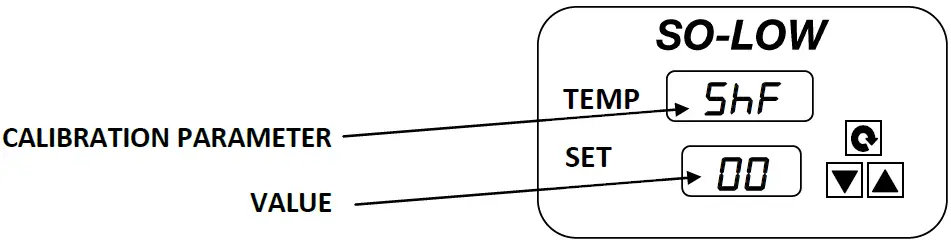
ONCE THE CALIBRATION PARAMETER HAS BEEN TURNED ON
- Hold the SCROLL KEY for 2 seconds and release. SHF should appear in the top display and the current calibration value should appear in the bottom display.
- The value can now be changed with UP or DOWN arrow keys.
- Once finished, press and release the SCROLL KEY to return to the main screen.
FUSE OR CIRCUIT BREAKER
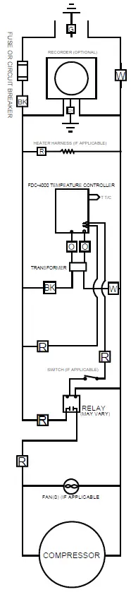
FDC4000 SS 115 VOLT
ALARM DIAGRAM
TEMPERATURE CONTROL
HOT WALL CONDENSER
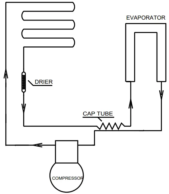
REFRIG. FLOW CHART
REFRIGERATION & HARDWARE PARTS LIST
Note:
When ordering parts, please have the Model & Serial number of the Freezer.
| COMPRESSOR MODEL | HP | VOLTAGE | HERTZ | PHASE | SO-LOW PART # |
| EMBRACO FFI12HBX | 1/ 3 | 115 | 50/60 | 1 | FF12-115 |
| LG | 1/ 5 | 115 | 50/60 | 1 | LG-115 |
| CONTROL MODEL | SO-LOW PART # |
| PARTLOW 1160 | 1160 |
| FDC 4100 | 4100 |
| FDC 4000 | 4000 |
| FDC 9300 | 9300 |
PLEASE NOTE:
IN ORDER TO PROVIDE YOU WITH THE CORRECT TEMPERATURE CONTROL, SO-LOW REQUIRES YOU TO PROVIDE THE SERIAL NUMBER OF YOUR FREEZER WHEN ORDERING.
| GENERAL PARTS | SO-LOW PART # |
| Compressor Relay No. SSAA-330-25-000 (Please Specify Voltage) | 21351-VOLTAGE |
| Sunon Fan Motor No. SP101A | FAN-SUN-SP |
| Sunon Fan Motor No. DP201A | FAN-SUN-DP |
| Mechantronics Fan Motor No. UF12A12-BTH | FAN-MEC-UF |
| Electrical Cord No. 8-3 (Please Specify Voltage) | PWRCRD-15A-VOLTAGE |
| REFRIGERATION PARTS | SO-LOW PART # |
| Capillary Tube No. R-CH | 712 |
| HARDWARE PARTS | SO-LOW PART # |
| Hasp for CH Model | CH-HASP |
| Chest Lid (For Models CH25-5 / CH45-5 / CH40-5) | LID-5 |
| Chest Lid Hinge (For Models CH25-5 / CH45-5 / CH40-5) | HINGE-CH-5 |
| Chest Lid (For Models CH25-9 / CH43-9) | LID-9 |
| Chest Lid Hinge (For Models CH25-9 / CH43-9) | HINGE-CH-9 |
| Chest Lid (For Models CH25-13 / CH40-13) | LID-13 |
| Chest Lid Hinge (For Models CH25-13 / CH40-13) | HINGE-CH-13 |
NOTE:
If you require an item that is not listed above, please contact the So-Low Service Department for assistance (513) 772-9410.
Future Design Controls, Inc.
7524 West 98th Place Bridgeview, IL 60455
Tel: (888) 751-5444
Fax: (888) 307-8014
Environmental Equipment Co., Inc.
10310 Spartan Dr., Cincinnati, Ohio 45215 USA
(513) 772-9410
e-mail: [email protected]
Fax (513) 772-0570
http://www.so-low.com


