![]() POWER COMMANDER 6
POWER COMMANDER 6
Installation Guide for: PC6-20015
Model Coverage: 2005-2009 Suzuki C90
PC6-20015 Power Commander 6
PARTS LIST
| 2 POWER COMMANDER DECALS 2 VELCRO STRIPS 1 ALCOHOL SWAB |
PLEASE READ ALL DIRECTIONS BEFORE STARTING INSTALLATION.
THE IGNITION MUST BE TURNED OFF BEFORE INSTALLATION.
x IPC6-20015.01
INPUT ACCESSORY GUIDE
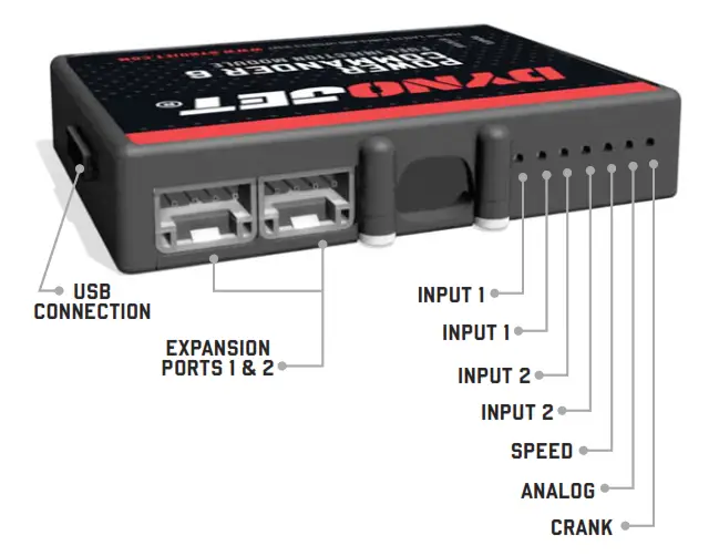
OPTIONAL ACCESSORY INPUTS
| Map | (Input 1 or 2) The PC6 has the ability to hold 2 different base maps. You can switch on the fl y between these two base maps when you hook up a switch to the MAP inputs. You can use any open/close type switch. The polarity of the wires is not important. |
| Shifter | (Input 1 or 2) Used for clutch-less full-throttle upshifts. Insert the wires from the Dynojet quick shifter into either Input 1 or Input 2. The polarity of the wires is not important. Set to Input 2 by default. |
| Speed | If your application has a speed sensor then you can tap into the signal side of the sensor and run a wire into this input. This will allow you to calculate gear position in the Control Center Software. Once the gear position is set up you can alter your map based on gear position and set up gear-dependent kill times when using a quick shifter. |
| Analog | This input is for a 0-5v signal such as engine temp, boost, etc. Once this input is established you can alter your fuel curve based on this input in the Power Core software. |
| Launch | You can connect a wire to either Input 1 or Input 2 and then the other end to a switch. This switch when engaged (continuity) will only allow the RPM to be raised to a certain limit (set in the software). When released, you will have full RPM. |
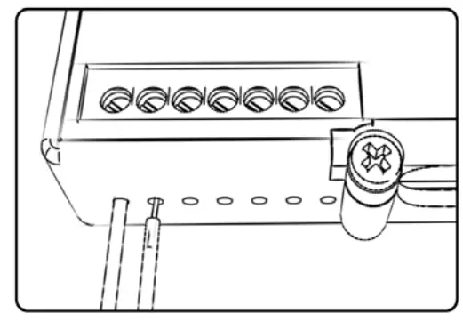
WIRE CONNECTIONS
To input wires into the PC6 fi rst remove the rubber plug on the backside of the unit and loosen the screw for the corresponding input. Using a 22-24 gauge wire, strip about 10mm from its end. Push the wire into the hole of the PC6 until it stops and then tightens the screw. Make sure to reinstall the rubber plug.
NOTE: If you tin the wires with solder it will make inserting them easier. 2 2005-2009 SUZUKI C90
 INSTALLATION GUIDE
INSTALLING THE POWER COMMANDER 6
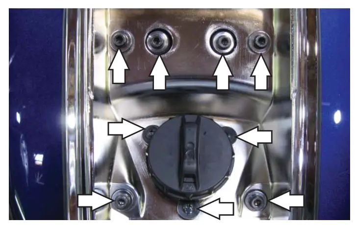
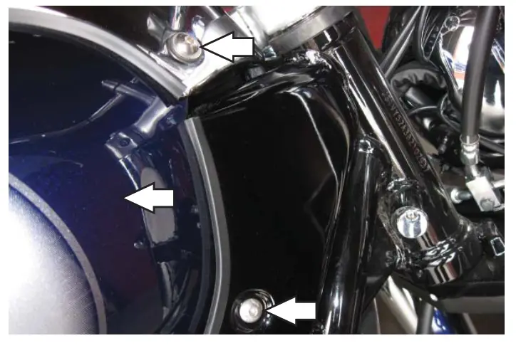
- Remove the main seat and the passenger seat.
- Remove the center gauge cluster.

- Remove the right and left cosmetic covers.
- Remove the air box by loosening the two hose clamps and disconnecting the air box temp sensor harness.

- Unplug the wiring harness from each injector.
- Lay the PC6 on top of the front valve cover temporarily.
- Plug the ORANGE colored wires of the PC6 in-line of the stock wiring harness and front injector.

- Plug the YELLOW colored wires of the PC6 in-line of the stock wiring harness and rear injector.
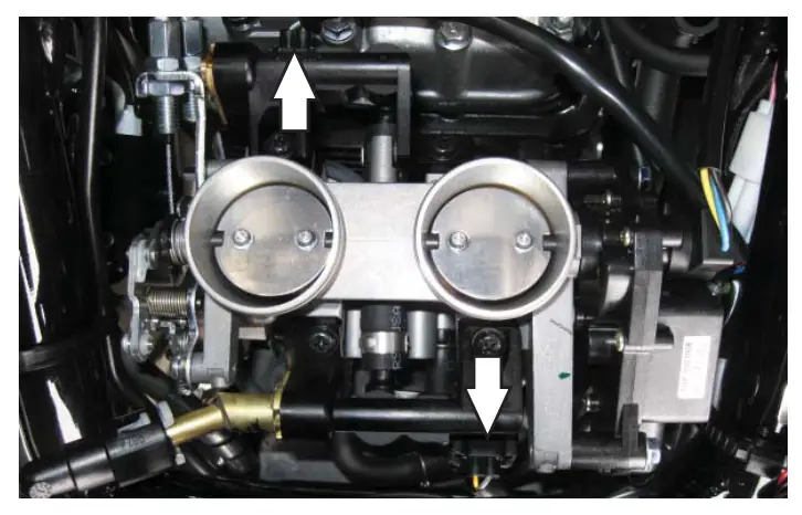
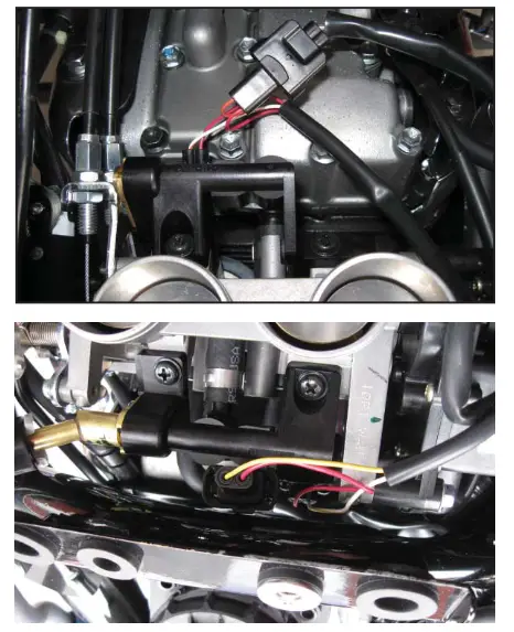
- Locate the Throttle Position Sensor on the right-hand side of the throttle bodies.
- Disconnect the wiring harness from the TPS.
- Plug the 3 pin connectors from the PC6 in-line of the stock TPS and wiring harness..

- Unscrew the front bolt that holds the ignition coil to the frame. Screw the bolt back in through the ground wire from the PC6.
- Reinstall the air box.

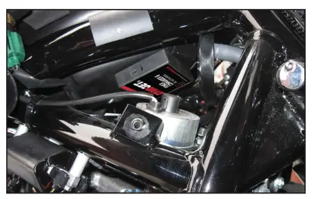
- Attach the PC6 to the bottom side of the air box using the supplied velcro.
Make sure to clean both surfaces with the alcohol swab fi rst. - Reinstall the removed bodywork.
Download the latest map fi les from our website at dynojet.com/tunes. Optional inputs:
Speed – PINK wire of speed sensor. Located behind R.H engine cover. Engine
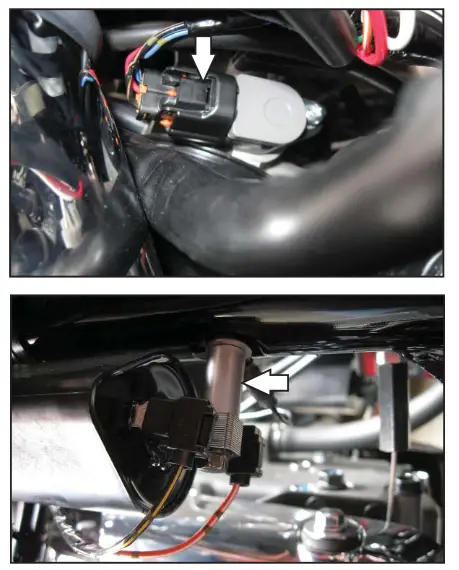
Temperature – BLACK/BLUE wire of BLACK 2-pin connector behind rear brake master cylinder. 12v source for
Autotune – BROWN wire of tail light connector under seat.
PUSH THE LIMIT
PC6-20015
2191 MENDENHALL DRIVE, NORTH LAS VEGAS, NV 89081 – 800-992-4993 – DYNOJET.COM
© 2005-2022 DYNOJET RESEARCH ALL RIGHTS RESERVED


