dh RGI-30 Gripper User Manual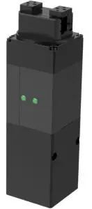
Revisions
Date | Version | Revised content |
20200426 | V1.0 | First edition, write wiring instructions and command instructions |
20200904 | V2.0 | Change some instructions , Update the description of IO mode |
20201010 | V2.1 | The structure of gripper is modified and the structure is lengthened. Modify the picture |
Specifications
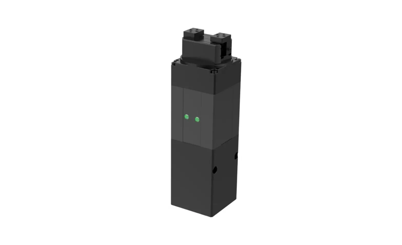
RGI-30 is an electric rotary gripper, The number represents the Maximum stroke. The gripper is equipped with a pair of parallel fingertips, which runs symmetrically during the movement. The main structure of the gripper is a cuboid structure with three installation positions, which can meet the different installation conditions of the equipment. It is equipped with an 8-core communication interface, as shown in Figure 1.1. It has the following characteristics:
- Controllable force/position/speed/angle: The gripper can program and adjust the grip position, grip force ,grip speed and angle.
- Multiple communication modes: The gripper supports Modbus RTU protocol and IO mode control. Other communication protocols such as USB and ETHERNET can be transferred through protocol converter.
- Gripping detection: The combination of force control and position control is adopted in the gripping process.
- Gripping feedback: The state of the gripper can be read by programming, and can also be judged according to the indicator of the gripper.
- Fingertips can be customized: Fingertips can be replaced according to situation, which is suitable for precision machining, parts assembly, and other fields.
 Figure 1.1 RGI-30 gripper
Performance Parameter
The specific parameters of RGI-30 gripper are listed in Table 1.1
Table 1.1 RGI-30 specifications
RGI-30 performance parameters. | |
Gripping force (per jaw) | 10-35N. |
| Opening/closing stroke (both sides) | 30 mm. |
Rotating torque. | 0.25 N·m. |
| The rotation range. | Unlimited |
Maximum rotation speed. | 1500°/ s . |
| Position repeatability (both sides) | ± 0.02mm |
Rotating repeat accuracy. | ± 0.02° |
Opening/closing time | 0.3/0.3S. |
| Weight. | 0.8kg. |
Ingress protection rating | IP20. |
| Nominal voltage | 24 V DC ± 10% |
Nominal current | 1.1A. |
| Peak current | 2A. |
Recommended operating environment | 0 to 40°C,85% RH or less. |
| Communication protocols | Modbus RTU (RS485), I/O. |
In the actual gripping, you should take the gripping angle and gripping position into account. The following right-angle coordinate system is established, and the corresponding directions of the X-axis, Y-axis, and Z-axis are shown in Figure 1.2 below. The force perpendicular to the gripped flat surface is used as Fz, the x-axis direction torque is Mx, the y-axis direction torque is My, and the z-axis direction torque is Mz. The RGI-30 ‘finger load table is shown in Table 1.2
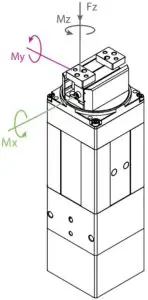
Figure 1.2 Torque diagram
Table 1.2 RGI-30 Finger load Table .
RGI-30 | |
Max allowable vertical load (static) | 150N |
| Max allowable moment Mx (static) | 2 N m |
Max allowable moment My (static) | 1.5 N m |
| Max allowable moment Mz (static) | 2.5 Nm |
Dimensions
The dimensions of gripper contain the specific size of the gripper, the mounting hole, as shown in Figure 1.3:
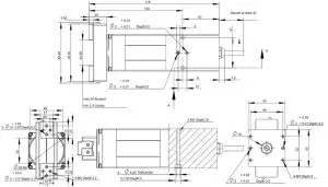
Figure 1.3 Dimensions
Indicator
The gripper can feed back the state of the gripper in real time. In addition to the command reading, it can also be judged on the color of the indicator:
Color description of indicator
- Uninitialize state: Red light blinks, other lights are off.
- Initialized State: the blue light is always on, indicating that it is in the operable state.
- Received command state: the red light blink once quickly (because the blue light is always on at this time, the gripper indicator light will looks like a purple light).
- Object Caught state: green light is always on, other lights are off.
- Object dropped state: green light blinking.
Pinout Description
The pinout of the gripper is shown in Figure 1.4, and the pin description is shown in Table 1.3.
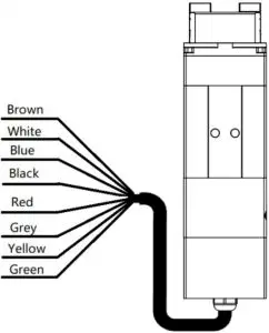
Figure1.4 Pinout assignment
Table 1.3 Pinout assignment
Wire color | Description |
Brown | INPUT 2 |
| White | INPUT 1 |
Blue | 485_B |
| Black | 485_A |
Red | 24 V |
| Grey/Pink | GND |
Yellow | OUTPUT 1 |
| Green | OUTPUT 2 |
Modbus-RTU Control
Wiring
Use the provided RS-485 to USB converter (see the schematic in Figure 1.1 below) to plug into a PC or other Controllers.
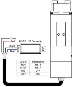
Figure 2.1 RS485 Connection
Warning
- Note the line order before connecting: Please note that the RGI power wire is red and GND wire is grey.
Default Communication Parameters
- Slave Address :1
- Baud Rate :115200
- Data Bits :8 bits
- Stop Bits :1 stop bit
- Parity :None
Modbus-RTU Description
RTU Framing
This gripper uses the standard Modbus-RTU protocol.
In RTU mode, the first field is the device address. The allowable characters transmitted for all fields are hexadecimal 0 … 9, A … F. Networked devices monitor the network bus continuously, including during the silent intervals. When the first field (the address field) is received, each device decodes it to find out if it is the addressed device.
A typical message frame is shown in Table 2.1.
Table 2.1 RTU Framing (Function Code:0x06)
Slave Address | Function | Register address | Register data | CRC |
| 01 | 06 | 01 00 | 00 01 | 49 F6 |
Slave Address: The Slave address of the gripper. The default is 1, you can also modify it through write different value to Slave Address register.
Function: The Function Code field tells the addressed slave what function to perform. Includes read or write registers function.
Register address: Specifies which registers reference to be written.
Register data: Specifies which value to be written. Each register (word – 16 bits) of the Modbus RTU protocol is composed of 2 bytes (8 bits) from the Gripper.
CRC: the CRC error-checking field contains a 16-bit value implemented as two eight-bit bytes. The CRC field is appended to the message as the last field in the frame. The low-order byte of the field is appended first, followed by the high-order byte. The CRC high-order byte is the last byte to be sent in the message.
Supported Modbus Function Code
This griper uses MODBUS- RTU. The following function codes are currently supported:
- 03 (HEX): Read Holding Registers
- 06 (HEX): Write Single Register
- 10 (HEX): Write Multiple Registers
Register Mapping
- The gripper’s Modbus-RTU registers consist of two types of registers: the basic control registers and the configuration registers.
- Basic control registers: initialization, force setting, reference position, speed, and some states.
- Configuration registers: gripper’s parameter configuration. Includes Modbus communication parameters and I/O parameters.
Table 2.2 Basic Control register map
Function | high- byte | low- byte | Description | Write | Read |
| Initialization | 0x01 | 0x00 | Initialize the gripper | 0x01:initialization; 0xA5: Fully initialization | Current setting |
| Force | 0x01 | Gripper’s force | 20-100 (%) | Force currently set | |
| Reserved | 0x02 | – | – | – | |
| Position | 0x03 | Position | 0-1000 (‰) | Reference position currently set | |
| Speed | 0x04 | Speed | 1-100 (%) | Speed currently set | |
| Rotation angle | 0x05 | Rotate to the specified angle. | -32768-32767,angle value. | Read the current setting | |
| Reserved | 0x06 | – | – | – | |
| Rotation speed | 0x07 | Rotate at a set speed. | 1-100% | Read the current setting. | |
| Rotation force | 0x08 | Rotate at a set force. | 20-100% | Read the current setting. | |
| Initialization state | 0x02 | 0x00 | Initialization state of the gripper | Read Only | 0:Uninitialized; 1:Initialized 2:Initializing |
| Gripper state | 0x01 | Gripper state | Read Only |
| |
| Position | 0x02 | gripper position | Read Only | Current actual position | |
| Rotating angle feedback. | 0x08. | Feedback on the current rotation angle. | Cannot be written. | Read the current value. | |
| Rotating initialization state feedback. | 0x0A. | Feedback rotation initialization state. | Cannot be written. |
| |
| Rotating state feedback. | 0x0B. | Feedback rotation state. | Cannot be written. |
|
Table 2.3 Configuration register map
Function | High byte | Low bytes | Description | Write | Read |
| Save Parameter | 0x03 | 0x00 | Save all the parameters | 0:default,1:Write all parameters to save | 0 |
| Initialization direction | 0x01 | Configure initialization direction | 0: Open,1:Close (default: 0) | Current setting | |
| Slave Address | 0x02 | Configure gripper Modbus address | 0-255 (default: 1) | Current setting | |
| Baud Rate | 0x03 | Configure gripper Modbus Baud rate | 0-5:115200,57600, 38400,19200,9600, 4800(default :0) | Current setting | |
| Stop Bits | 0x04 | Configure gripper Modbus stop bits | 0:1 stop bit; 1:2 stop bits (default: 0) | Current setting | |
| Parity | 0x05 | Configure gripper Modbus Parity | 0: None parity; 1: Odd parity; 2: Even parity (default: 0) | Current setting | |
| I/O Parameters Test | 0x04 | 0x00 | Test I/O parameters | 1;2;3;4 | Current setting |
| I/O Mode Switch | 0x02 | I/O control switch | 0:OFF,1:ON | Current setting | |
| I/O Parameter Configuration | 0x05- 0x10 | Four groups of I/O parameters | position 1,force 1,speed 1 to position 4,force 4, speed 4 | Current setting |
Register Description
Initialization
This register is used to initialize the gripper.
Write: If write 1 (0x01 hex) to this register, the gripper will be initialized (fingers move to the minimal or maximum position and rotation to find the 0 degree The initialization direction depends on the value of initialization direction register). If write 165 (0xA5 hex) to this register will fully initialize the gripper( find the minimal and maximum position).
Read: if gripper need to be initialized or have initialized, this register value is 0; and if gripper is in initializing process, this register value is 1.
The register address is 0x0100. The description of this register is shown in Table 2.4.
Table 2.4 Initialization
| Function | Address | Description | Write | Read |
| Initialization | 0x0100 | Initialize the gripper | 0x01:initialize; 0xA5: Fully initialize | Current setting |
The gripper needs to be initialized before control.
The sample command is as follows:
Initialize (write):
Send: 01 06 01 00 01 49 F6
Receive: 01 06 01 00 01 49 F6
Reinitialize(write):
Send: 01 06 01 00 00 A5 48 4D
Receive: 01 06 01 00 00 A5 48 4D
Force
This register is used to set Force. It defines the current for the Gripper. If the current limit is exceeded, the fingers stop and trigger an object detection.
The address is 0x0101. The description of this register is shown in Table 2.5.
Table 2.5 Force
Function | Address | Description | Write | Read |
| Force | 0x0101 | Gripper’s closing force | 20-100 (%) | Force currently set |
The force value range is 20-100, the corresponding value is 00 14–00 64(Hexadecimal).
Example:
Set 30% closing force (write):
Send: 01 06 01 01 1E 59 FE
Return: 01 06 01 01 1E 59 FE
Read the closing force currently set (read):
Send: 01 03 01 01 00 01 D4 36
Return: 01 03 02 xx xx crc1 crc2
Position
This register is used to set the reference position of gripper’s fingers, then the fingers will move to the position immediately.
The address is 0x0103. The description of this register is shown in Table 2.6.
Table 2.6 Position
Function | Address | Description | Write | Read |
| Position | 0x0103 | Reference Position | 0-1000 (‰) | Reference position currently set |
The reference position value range is 0-1000 (‰), the corresponding value is 00 00 – 03 E8(Hexadecimal).
Example:
Set 500‰ position (write):
Send: 01 06 01 03 01 F4 78 21
Return: 01 06 01 03 01 F4 78 21
Read the reference position currently set(read):
Send: 01 03 01 03 00 01 75 F6
Return: 01 03 02 xx xx crc1 crc2
Speed
This register is used to set the Gripper closing and opening speed.
The address is 0x0104. The description of this register is shown in Table 2.7.
Table 2.7 Speed Instructions
Function | Address | Description | Write | Read |
Speed | 0x0104 | Speed | 1-100 (%) | Speed currently set |
The speed value range is 1-100 ,The corresponding value is 00 01 – 00 64(Hexadecimal).
Example:
Set 50% speed (write):
Send: 01 06 01 04 00 32 48 22
Return: 01 06 01 04 00 32 48 22
Read the current speed (read):
Send: 01 03 01 04 00 01 C4 37
Return: 01 03 02 xx xx crc1 crc2
Rotation angle
This register is used to set the gripper angle of rotation.
The address is 0x0105. The description of this register is shown in Table 2.8.
Table 2.8 The angle of rotation
Function | Address | Description | Write | Read |
| Rotation angle | 0x0105 | Rotate to the specified angle. | -32768-32767 | Read the current setting |
The amgle of rotation is -32768-32767 , The corresponding value is 0xF000 – 0x7FFF(Hexadecimal).
Example:
Set 180% angle (write):
Send: 01 06 01 05 00 B4 98 40
Return: 01 06 01 05 00 B4 98 40
Read the current angle (read):
Send: 01 03 01 05 00 01 95 F7
Return: 01 03 02 xx xx crc1 crc2
Be careful
- Rotation angle is represented by a reverse code.
If the rotation angle is positive, the reverse code of positive number is the same as the original code.
For example, the inverse code of 360° is 0168 (0x).
Set 360% angle: 01 06 01 05 01 68 98 49
When the rotation angle is negative, the inverse code of negative number is the reverse of positive number bit by bit, and the sign bit is 1.
For example, the inverse code of – 360° is FE97 (0x).
Set -360% angle: 01 06 01 05 Fe 97 99 F9
Rotation speed
This register is used to set the speed of rotation.
The address is 0x0107. The description of this register is shown in Table 2.9.
Table 2.9 The speed of rotation
Function | Address | Description | Write | Read |
| Rotation speed | 0x0107 | Rotate at a set speed. | 1-100% | Read the current setting. |
The speed of rotation is 1-100(%),The corresponding value is 0x0001 –0x0064(Hexadecimal).
Example:
Set 50% rotation speed (write):
Send: 01 06 01 07 00 32 B8 22
Return: 01 06 01 05 00 B4 B8 22
Read the current speed (read):
Send: 01 03 01 07 00 01 34 37
Return: 01 03 02 xx xx crc1 crc2
Rotation force
This register is used to set the force of rotation.
The address is 0x0108. The description of this register is shown in Table 2.10.
Table 2.9 The force of rotation
Function | Address | Description | Write | Read |
| Rotation force. | 0x0108 | Rotate at a set force | 20-100% | Read the current setting. |
The force of rotation is 20-100(%),The corresponding value is 0x0014 –0x0064(Hexadecimal).
Example:
Set 50% force (write):
Send: 01 06 01 08 00 32 88 21
Return: 01 06 01 05 00 B4 88 21
Read the current force (read):
Send: 01 03 01 07 00 01 34 37
Return: 01 03 02 xx xx crc1 crc2
Initialization State
This register is used to store current initialization state of gripper, you can get the initialization state by reading this register.
The address is 0x0200. The description of this register is shown in Table 2.11.
Table 2.11 Initialization State
Function | Address | Description | Write | Read |
| Initialization State | 0x0200 | Initialization state of the gripper | Read Only | 0:Uninitialized; 1:Initialized 2:Initializing |
Example:
Read initialization state (read):
Send: 01 03 02 00 00 01 85 B2
Return: 01 03 02 00 00 B8 44
Gripper State
This register is used to store the Gripper state, you can get the state of gripper by reading this register.
And the address is 0x0201. The description of this register is shown in Table 2.12.
Table 2.12 Gripper State
Function | Address | Description | Write | Read |
| Gripper State | 0x0201 | the gripper state | Read Only |
|
States Description
Different values indicate different states of the gripper. The descriptions of states are as follows:
- 00: Fingers are in motion .
- 01: Fingers are at reference position. No object detected or object has been dropped.
- 02: Fingers have stopped due to an object detection.
- 03: Fingers are at reference positon due to object has been dropped after the gripper caught object.
Example:
Read gripper state (read):
Send: 01 03 02 01 00 01 D4 72
Return: 01 03 02 00 02 39 85(02: object caught)
Current Position
This register is used to store the Actual position of the Gripper.
The address is 0x0202. The description of this register is shown in Table 2.13.
Table 2.13 Current Position
Function | Address | Description | Write | Read |
| Current Position | 0x0202 | Gripper actual position | Read Only | Current actual position |
Example:
Read actual position (read):
Send: 01 03 02 02 00 01 24 72
Return: 01 03 02 xx xx crc1 crc2
Rotating angle feedback
This register is used to store the Actual rotating angle of the Gripper.
The address is 0x0208. The description of this register is shown in Table 2.14.
Table 2.14 Rotating angle feedback
Function | Address | Description | Write | Read |
| Rotating angle feedback. | 0x0208. | Feedback on the current rotation angle. | Cannot be written. | Read the current value. |
Example:
Read actual rotation angle (read):
Send: 01 03 02 08 00 01 04 70
Return: 01 03 02 xx xx crc1 crc2
Rotating initialization state feedback.
This register is used to store the Rotating initialization state feedback. of the Gripper.
The address is 0x020A. The description of this register is shown in Table 2.15.
Table 2.15 Rotating initialization state feedback.
Function | Address | Description | Write | Read |
| Rotating initialization state feedback. | 0x020A. | Feedback rotation initialization state. | Cannot be written. |
|
Example:
Read actual Rotating initialization state feedback (read):
Send: 01 03 02 0A 00 01 A5 B0
Return: 01 03 02 xx xx crc1 crc2
Rotating state feedback.
This register is used to store the Rotating state feedback. of the Gripper.
The address is 0x020B. The description of this register is shown in Table 2.16.
Table 2.16 Rotating state feedback
Function | Address | Description | Write | Read |
| Rotating state feedback. | 0x020B. | Feedback rotation state. | Cannot be written. |
|
Example:
Read actual Rotating state feedback (read):
Send: 01 03 02 08 00 01 04 70
Return: 01 03 02 xx xx crc1 crc2
Save Parameter
This register is used to Save Parameter.
Write 1 to this register to save all parameter, If you modified the I/O or communication parameters.
The address is 0x0300. The description of this register is shown in Table 2.17.
Table 2.17 Save Parameter
Function | Address | Description | Write | Read |
| Save Parameter | 0x0300 | Save register’s value to Flash |
| 0 |
Example:
Save Parameter (Write):
Send: 01 06 03 00 00 01 48 4E
Return: 01 06 03 00 00 01 48 4E
NOTE
- The Saving process will take 1-2 seconds, and the gripper won’t response to other command during this process. The gripper will response this command after saving process finished.
Initialization Direction
This register is used to set Initialization Direction of gripper.
The address is 0x0301. The description of this register is shown in Table 2.18.
Table 2.18 Baud Rate
Function | Address | Description | Write | Read |
| Baud Rate | 0x0301 |
|
| Current setting |
The value of this register is 0 by default.
If the register value is 0, when you send the initialization command, the gripper finger will open and find the maximum position.
If the register value is 1, when you send the initialization command, the gripper finger will close and find the minimal position.
Example:
Write 0 to initialization direction register:
Send: 01 06 03 01 00 00 D8 4E
Return: 01 06 03 01 00 00 D8 4E
Slave Address
This register is used to set Slave Address of gripper.
The address is 0x0302. The description of this register is shown in Table 2.19.
Table 2.19 Slave Address
| Function | Address | Description | Write | Read |
| Slave Address | 0x0302 |
| 0-255 (default: 1) | Current setting |
The value of this register is 1 by default.
Example:
Set the Slave Address to 1 (write):
Send: 01 06 03 02 00 01 E9 8E
Return: 01 06 03 02 00 01 E9 8E
NOTE
- Please make sure that no other networked device has the same slave address as the gripper.
Baud Rate
This register is used to set Baud Rate of gripper.
The address is 0x0303. The description of this register is shown in Table 2.20.
Table 2.20 Baud Rate
Function | Address | Description | Write | Read |
| Baud Rate | 0x0303 | Configure gripper Modbus Baud rate | 0-5:115200,57600, 38400,19200,9600, 4800(default: 0) | Current setting |
The value of this register is 0 by default, corresponding to a baud rate of 115200.
Example:
Set gripper baud rate to115200 (write):
Send: 01 06 03 03 00 00 79 8E
Return: 01 06 03 03 00 00 79 8E
Stop Bits
This register is used to set Stop Bits of gripper.
The address is 0x0302. The description of this register is shown in Table 2.21.
Table 2.21 Stop bits settings
Function | Address | Description | Write | Read |
| Stop Bits | 0x0304 | Configure gripper Modbus stop bits | 0:1 stop bit 1:2 stop bits ( default: 0) | Current setting |
The value of this register is 0 by default, corresponding to 1 stop bit.
Example:
Set the gripper stop bit to 1 stop bit (write):
Send: 01 06 03 04 00 00 C8 4F
Return: 01 06 03 04 00 00 C8 4F
Parity
This register is used to set Parity of gripper.
The address is 0x0305. The description of this register is shown in Table 2.22.
Table 2.22 Parity
Function | Address | Description | Write | Read |
| Parity | 0x0305 | Configure gripper Modbus Parity |
| Current setting |
The value of this register is 0 by default, corresponding to None Parity.
Example:
Set the gripper’s Parity to None Parity (write):
Send: 01 06 03 05 00 00 99 8F
Return: 01 06 03 05 00 00 99 8F
Test I/O Parameters
This register is used to test the I/O Parameters.
The address is 0x0400. The description of this register is shown in Table 2.23.
Table 2.23 I/O Control
Function | Address | Description | Write | Read |
| Test I/O Parameters | 0x0400 | Test I/O Parameters | 1;2;3;4 | Current setting |
This register can be used to directly test 4 groups of I/O parameters through Modbus-RTU to ensure that the I/O parameters are appropriate. For example, Write 1 to this register, the gripper will execute action with the first group of I/O parameter.
Example:
Control gripper by using first group of I/O parameter (write):
Send: 01 06 04 00 00 01 49 3A
Return: 01 06 04 00 00 01 49 3A
I/O Mode Switch
This register is used to turn I/O Control Mode ON or OFF.
The address is 0x0402. The description of this register is shown in Table 2.24
Table 2.24 I/O Mode Switch
Function | Address | Description | Write | Read |
| I/O Mode Switch | 0x0402 | I/O Control Switch | 0:OFF,1:ON | Current setting |
If you have written 1 to this register and have saved all parameters, the gripper will be initialized automatically after power on.
When the I/O Control Mode is turned on, the gripper can respond to Modbus-RTU commands and I/O, but I/O has priority.
The control method in different mode is shown in Table 2.252.
Table 2.25 Control method
Switch State | Description | Modbus-RTU | I/O |
0 | I/O control mode off | YES | No |
| 1 | I/O control mode on | YES | YES |
Example:
Set the I/O control mode switch off (write):
Send: 01 06 04 02 00 00 29 3A
Return: 01 06 04 02 00 00 29 3A
NOTE
- If you just need to control the gripper through Modbus RTU, you should write 0 to this register and save all parameters to turn off the I/O control mode.
I/O Parameter Configuration
Those registers are used to Set the I/O Parameters.
The address is 0x0405-0x0410. The description of this register is shown in Table 2.26.
Table 2.26 I/O Parameter Configuration
| Function | High- byte | Low bytes | Description | Write | Read |
I/O Group 1 | 0x04 | 0x05 | position 1 | 0-1000‰ | Current setting |
| 0x06 | force 1 | 20-100 % | |||
0x07 | speed 1 | 1-100 % |
I/O Group 2 | 0x08 | position 2 | 0-1000‰ | ||
0x09 | force 2 | 20-100 % | |||
| 0x0A | speed 2 | 1-100 % | |||
I/O Group 3 | 0x0B | Rotation angle 1 | -32768-32767 | ||
| 0x0C | Rotation speed 1 | 1-100 % | |||
0x0D | Rotation force 1 | 20-100 % | |||
| I/O Group 4 | 0x0E | Rotation angle 2 | -32768-32767 | ||
0x0F | Rotation speed 2 | 1-100 % | |||
| 0x10 | Rotation force 2 | 20-100 % |
IO parameter configuration can be used to configure IO parameters. Take the first set of target position as 300, target force as 30% and target speed as 30% as an example
Example:
Set the first group of I/O parameter (write) :
Send: 01 06 04 05 01 2C 98 B6 (Reference position: 300‰)
Return: 01 06 04 05 01 2C 98 B6
Send: 01 06 04 06 00 1E E8 F3 (Force: 30%))
Return: 01 06 04 06 00 1E E8 F3
Send: 01 06 04 07 00 1E B9 33 (Speed: 30%)
Return: 01 06 04 07 00 1E B9 33
IO parameter address is continuous address, and four groups of IO parameters can be configured at one time by using the function code of 0x10, as follows:
Continuous multiple address write(write) [Group1: 1000 ‰ position;20%force;10%speed
Group 2:100‰position;20%force;2%speed Group 3: 0‰position;100%force;5%speed Group 4:592‰position;100%force;10%speed]:
Send: 01 10 0405 000C 18 03e8 0014 000A 0100 0014 0002 0000 0064 0005 0250 0064 000a 9f 44
Return: 01 10 04 05 00 0C D1 3D
I/O Control
The I/O mode is a common control method in industry.
The grippers will monitor the pin states of Input 1 and Input 2 (0V and high resistance states).
Input 1 controls the position and Input 2 controls the angle.. You can control this gripper through
changing the states of Input 1 and Input 2. As shown in Table 3.1(a) and. Table 3.1(b).
Table 3.1(a) Input 1 State
Pinout | Function | INPUT 1 | Pin state | Perform action |
| INPUT 1 | Position | High resistance | 0 | Target position 1,target force 1,target speed 1 |
| 0V | 1 | Target position 2,Target Force 2,Target Speed 2 |
Table 3.1(b) Input 2 State
Pinout | Function | INPUT 1 | Pin state | Perform action |
| INPUT 2 | Rotation | High resistance | 0 | Rotation angle 1, rotation speed 1, rotation force 1 |
| 0V | 1 | Rotation angle 2, rotation speed 2, rotation force 2 |
The input pin controls the position and rotation, and the two pins have sequence. According to the actual situation, they can confirm whether they move first and then rotate or rotate and then move.
You can also get the gripper state by detecting the states of Output1 and Output 2(0V and high resistance states). as shown in Table 3.2.
Table 3.2 Output1 Output2 State
I/O State (OUT1 OUT2) | State description |
0 0 | Fingers are in motion |
1 0 | Fingers are at reference position, |
| 0 1 | Fingers have stopped due to an object detection |
NOTE
- Please make sure that the I/O hardware type of the gripper is compatible with your controller’s.
The four states of IO mode can be configured through Modbus RTU protocol of RS485, or the parameters of gripper can be configured through our debugging software. Please refer to the previous section for specific configuration mode. After the four groups of parameters are configured, the gripper can be controlled by setting the Input 1 and Input 2 pin states, and the grip state can be obtained by detecting the Output 1 and Output 2.
Wiring
In I/O control mode, there are six wires need to be connected, including Input 1, Input 2, 24 V, Output 2, Output 1, GND. Refer to Table 3.3 for specific line sequence and color.
The gripper’s Output pin should be connected to the Controller’s Input pin. And the gripper’s Input pin should be connected to the Controller’s Output pin.
Table 3.3 wire Description
Wire color | Description |
Brown | INPUT 2 |
| White | INPUT 1 |
Blue | 485_B |
| Black | 485_A |
Red | 24 V |
| Grey/Pink | GND |
Yellow | OUTPUT 1 |
| Green | OUTPUT 2 |
I/O Setting
The diagram of IO operation steps is as follows:

Configure IO
Connect 24 V, GND and 485_ A and 485_ B. Then you can use I/O Parameter Configuration to configure four groups of IO parameters .It is recommended to use serial port debugging software at PC for configuration. IO parameters are configured as continuous address, and 12 groups of data including 0x0405-0x0410 need to be set.
You can configure the IO parameters of the gripper in two ways, as follows:
The first way:
Use the test software of the gripper for configuration. As shown in figures 3.1 (a) and 3.1 (b)
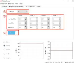
Figure 3.1 (a)Graphical configuration
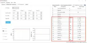
Figure 3.1 (b) Test software register configuration
The second way:
You can use continuous multiple register write 10 (HEX):
Send: 01 10 0405 000C 18 03e8 0014 000A 0100 0014 0002 0000 0064 0005 0250 0064 000a 9f 44
Receive: 01 10 04 05 00 0C D1 3D
Open IO
Turn on the IO mode switch and write 01 at the register of 0x0402 to open it, as shown below:
The specific instructions are as follows:
Send: 01 06 04 02 00 01 E8 FA
Return: 01 06 04 02 00 01 E8 FA
Save Settings
Save the configured parameters, and write 01 at the register of 0x300 for saving.
Send: 01 06 03 00 01 48 4e
Return: 01 06 03 00 01 48 4e
Restart
After power off, you can connect the input and output to the corresponding equipment, and power on after confirming that the wiring is correct. The gripper will be initialized automatically.
Then the gripper is controlled according to the input signal, and the running state is feedback through output.


