![]() ILCA-77M2 Interchangeable Lens Digital Camera
ILCA-77M2 Interchangeable Lens Digital Camera
Owner’s Manual
ILCA-77M2 Interchangeable Lens Digital Camera
ILCA-77M2/77M2M/77M2Q
SERVICE MANUAL
Ver. 1.2 2016.01
Revised-2
Replace the previously issued
SERVICE MANUAL 9-834-796-32 with this Manual.
US Model
Canadian Model
AEP Model
UK Model
Russian Model
E Model
Indian Model
Australian Model
Chinese Model
Korea Model
Japanese Model
SERVICE NOTE (Check the following note before the service.)
1-1. METHOD FOR REPLACING THE P.O.I.
1-2. PRECAUTION ON REPLACING THE AM-1004 BOARD
1-3. NOTES FOR REPLACING THE EVF DISPLAY DEVICE (LCD902) OR THE AM-1004 BOARD
1-4. CHECKING THE Wi-Fi FUNCTION
1-5. METHOD FOR CHECKING THE AS SLIDER UNIT (863)
1-6. METHOD FOR ADJUSTING THE TENURE REVISE
1-7. METHOD FOR REPLACING THE AS SLIDER B ASSY T
1-8. METHOD FOR REPLACING THE AS HOLDER ACTUATOR ASSY
1-9. NOTE ON REMOVING THE AP IRIS RING
1-10. HOW TO CHARGE THE APERTURE
1-11. METHOD OF CONFIRMING THE PHASES OF AP IRIS RING AND AP SENSOR GEA
[About the service of this model]
ILCA-77M2M/77M2Q are commodities that packed the Interchangeable Lens Digital Camera and Interchangeable Lenses.
Refer to each following service manual the Interchangeable Lens kit, when you repair.
INTERCHANGEABLE LENS DIGITAL CAMERA
The components identified by mark 0 or dotted line with mark 0 are critical for safety. Replace only with the part number specified.
| Model | Lens | Service Manual of Lens |
| ILCA-77M2 | No supplied lens | No supplied lens |
| ILCA-77M2M | SAL18135 (DT I 8-135mm F3.5-5.6 SAM) | 9-834-6771M |
| ILCA-77M2Q | SAL 1650 (DT 16-50mm F2.8 SSM) | 9-834-6154M |
Revision History
| Ver. | Date | History | Contents | S.M. Rev. issued |
| 1.0 | 2014.05 | Official Release | — | — |
| 1.1 | 2015.08 | Revised-1 (A1 15-020) | • Addition of Indian model. Page 3, 2-1, 2-18 | Yes |
| 1.2 | 2016.01 | Revised-2 (A2 15-106) | Addition of ASSEMBLY. Page 2-6, 3-2 | Yes |
2-1. EXPLODED VIEWS
2-1-1. OVERALL SECTION-1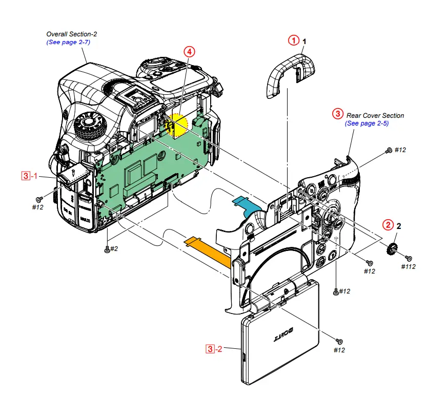
DISASSEMBLY
1. Remove in numerical order (1 to 4) in the left figure.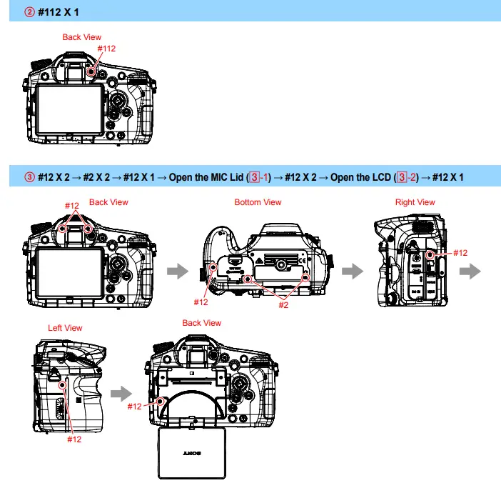
DISCHARGING OF THE CHARGING CAPACITOR
Screw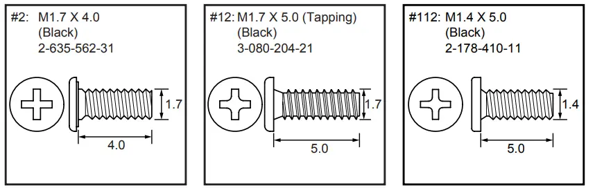
2-1-2. REAR COVER SECTION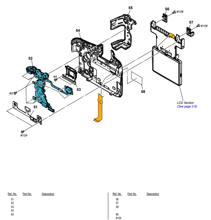
Screw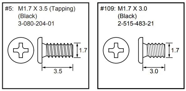
Ver. 1.2 2016.01
The changed portions from Ver. 1.1 are shown in blue.
2-1-3. LCD SECTION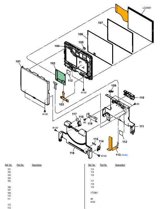
Screw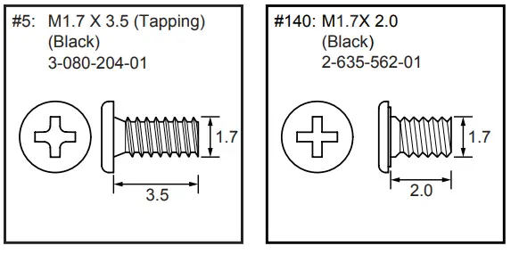
Note
Note: Refer to “Assembly-6: Notes on Attaching the LCD022 Flexible Board”.
2-1-4. OVERALL SECTION-2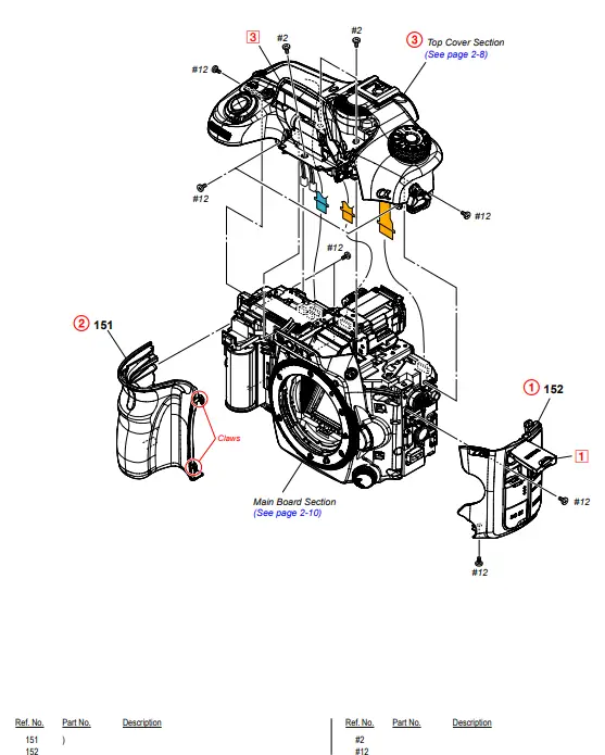
DISASSEMBLY
1. Remove in numerical order (1 to 3) in the left figure.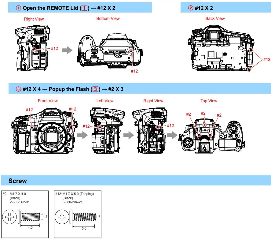
2-1-5. TOP COVER SECTION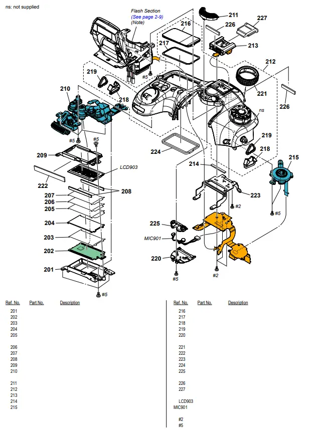
Screw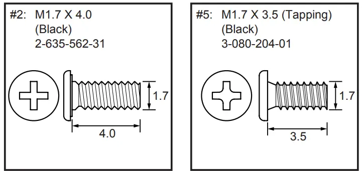
Note
Note: Refer to “Assembly-1: Routing of the Flash Harness”.
2-1-6. FLASH SECTION
ns: not supplied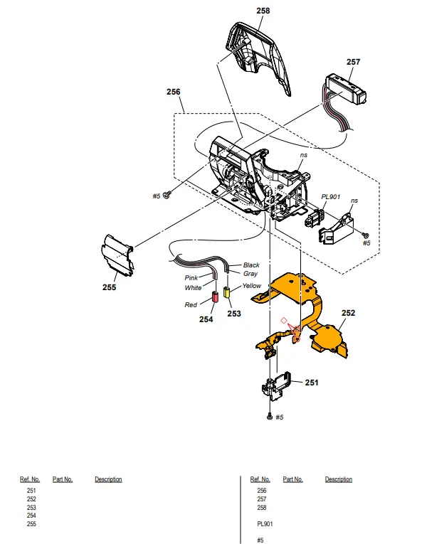
DISASSEMBLY
1. The meaning of the symbol in left figure is as follows. Be careful when you remove it.
◇: Solder
Screw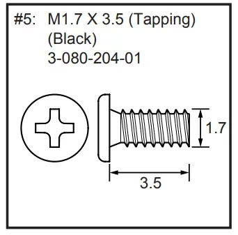
2-1-7. MAIN BOARD SECTION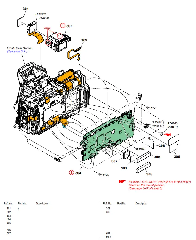
DISASSEMBLY
1. Remove in numerical order (1 to 2) in the left figure.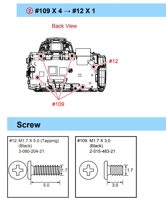
Note
Note 1: Replace the battery holder (BH6660) together when replacing the lithium secondary battery (BT6660) on the AM-1004 board. (The battery holder removed once cannot be used again.)
When mounting these parts, mount the new battery holder first and attach the new lithium storage battery next.
Note 2: Refer to “1-3. NOTES FOR REPLACING THE EVF DISPLAY DEVICE (LCD902) OR THE AM-1004 BOARD” on pages 1-2.
2-1-8. FRONT COVER SECTION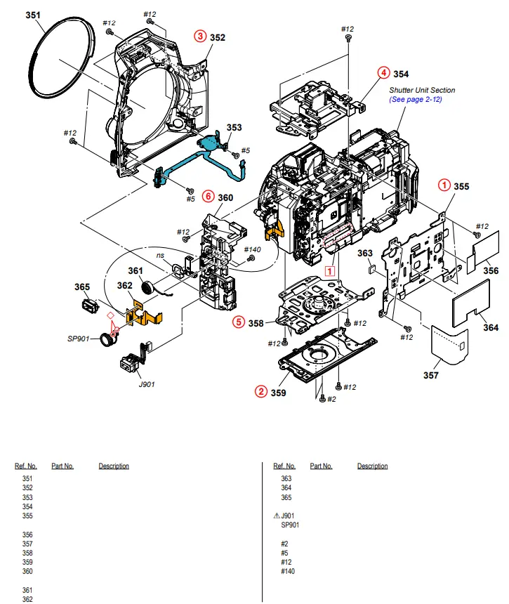
DISASSEMBLY
1. Remove in numerical order (1 to 6) in the left figure.
2. The meaning of the symbol in left figure is as follows. Be careful when you remove it.
◇: Solder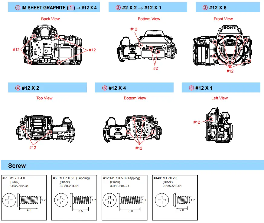
2-1-9. SHUTTER UNIT SECTION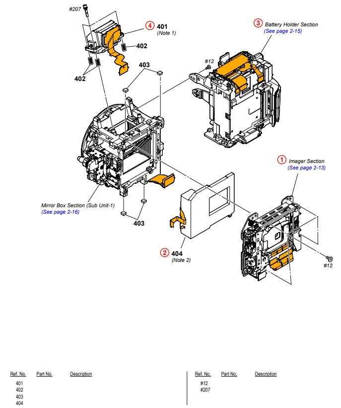
DISASSEMBLY
1. Remove in numerical order (1 to 4) in the left figure.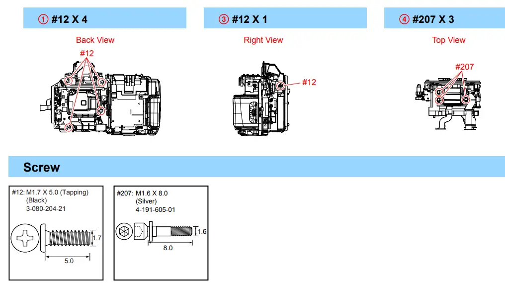
Note
Note 1: Refer to “Assembly-2: Notes on Assembling the ALX-8800 (AF Module)”.
Note 2: Refer to “Assembly-3: Notes on Installing the Shutter Unit (AFE-3111)”.
2-1-10. IMAGER SECTION
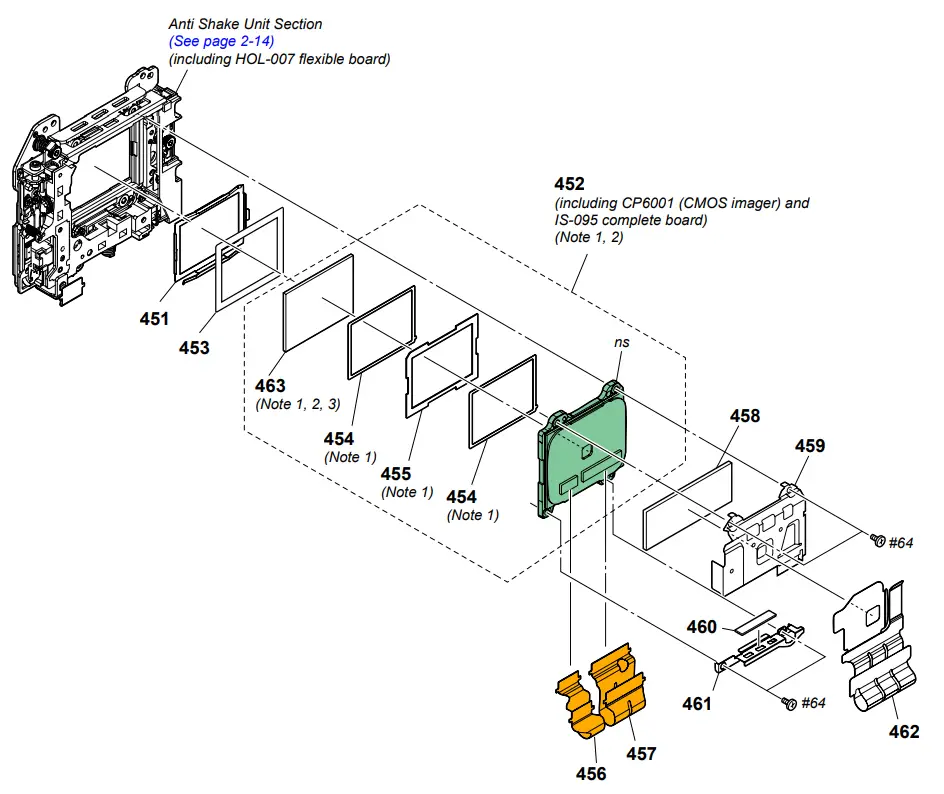
Note 1: Refer to “3-2. CLEANING PROCEDURE OF OLPF” on pages 3-2 for a method of cleaning the OLPF.
Note 2:
Precautions for Replacement of Imager
• If the imager has been replaced, carry out all the adjustments for the camera section.
• As the imager may be damaged by static electricity from its structure, handle it carefully like for the MOS IC.
In addition, ensure that the receiver is not covered with dust nor exposed to strong light.
| Ref. No. 451 452 453 454 455 456 457 458 | Part No. | Description |
Screw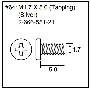
Note
Note 3 : Refer to the following statements when replacing the Optical filter block.
Method of Removal
(1) Pour resolvent (alcohol or cleaning agent) between the imager and the IM spacer.
* Wait for the adhesive power of the IM spacer weakens.
(2) Remove the IM spacer from the imager.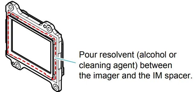
Method of Attachment
(1) Attach the two IM GS tapes and the Optical filter block by aligning them with the outer shape of the IM spacer evenly.
* Confirm the mounting direction of the Optical filter block referring to “3-1. ASSEMBLY”.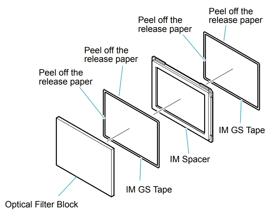
(2) Set the Optical filter block in its attachment jig (J-6082-737-A), with the attached adhesive side of IM spacer facing upward.
(3) Press the imager down into the jig as shown below to attach it to the Optical filter block.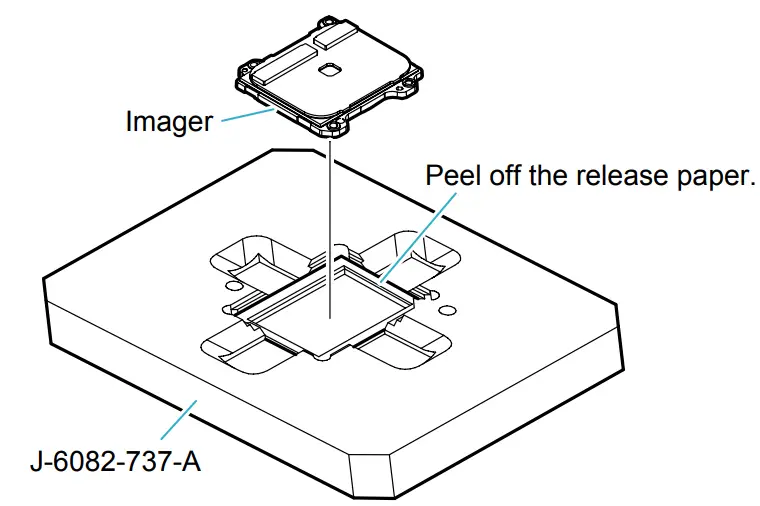
2-1-11. ANTI SHAKE UNIT SECTION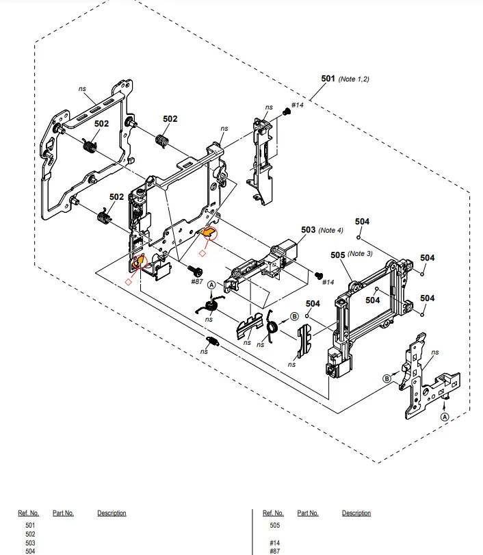
DISASSEMBLY
1. The meaning of the symbol in the left figure is as follows. Be careful when you remove it.
◇: Solder
Screw
Note
Note 1: Refer to “1-5. METHOD FOR CHECKING THE AS SLIDER UNIT (863)” on page 1-3 when checking the AS Slider Unit (863).
Note 2: Refer to “1-6. METHOD FOR ADJUSTING THE TEBURE REVISE” on page 1-3 when adjusting the Tebure Revise.
Note 3: Refer to “1-7. METHOD FOR REPLACING THE AS SLIDER BASSY
T” on pages 1-4 when replacing the AS Slider B Assy.
Note 4: Refer to “1-8. METHOD FOR REPLACING THE AS
HOLDER ACTUATOR ASSY” on page 1-5 when replacing the AS Holder Actuator Assy.
2-1-12. BATTERY HOLDER SECTION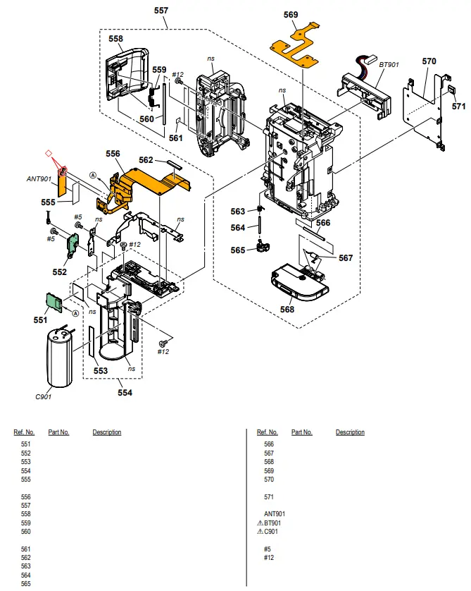
DISASSEMBLY
1. The meaning of the symbol in the left figure is as follows. Be careful when you remove it.
◇: Solder
Screw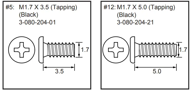
2-1-13. MIRROR BOX SECTION (SUB UNIT-1)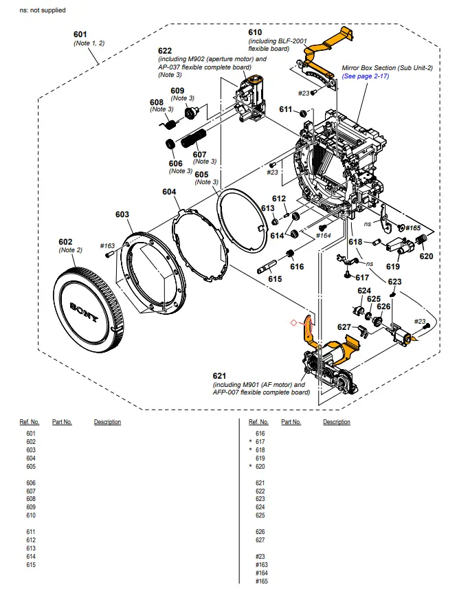
DISASSEMBLY
1. The meaning of the symbol in left figure is as follows. Be careful when you remove it.
◇: Solder
Iris Ring Removal
Rotate the Iris Ring clockwise, and remove it at the stop position (iris-in-end).
At this time, do not rotate the Iris Joint Gear of the AP Aperture Unit.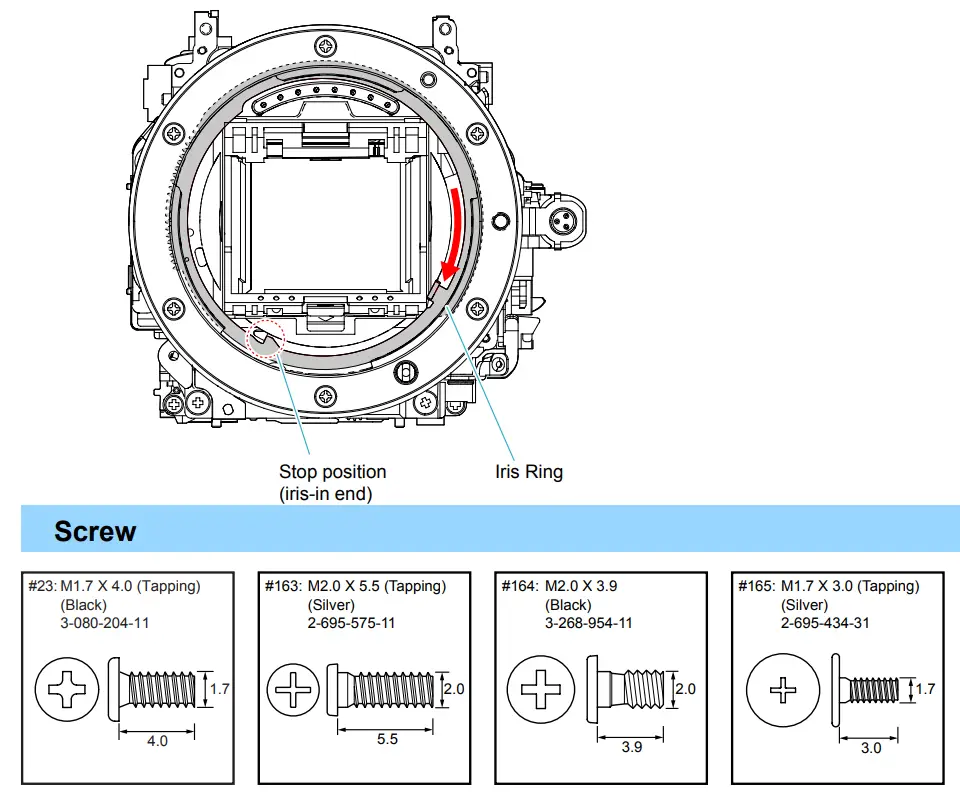
Note
Note 1: Refer to “Assembly-4: Notes on Assembling the Mirror Box Sub Unit”.
Note 2: The MB MIRROR BOX SUB UNIT includes a protective BODY CAP. This part is supplied only with the MB MIRROR BOX SUB UNIT.
Note 3: Refer to “1-9. NOTE ON REMOVING THE AP IRIS RING,” on page 1-5, “1-10. HOW TO CHARGE THE APERTURE” on page 1-6 and “1-11. METHOD OF CONFIRMING THE
PHASES OF AP IRIS RING AND AP SENSOR GEAR” on page 1-6.
2-1-14. MIRROR BOX SECTION (SUB UNIT-2)
Screw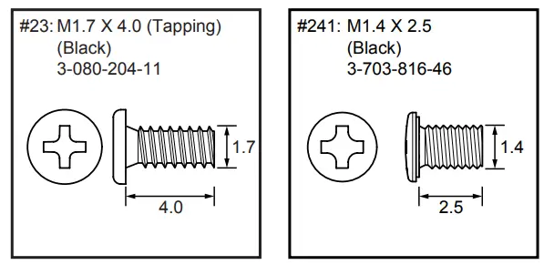
Note
Note 1: If the MB Mirror Frame Holder Assy (P.O.I.) is raised and then pushed from the front side with the Shutter Unit (AFE3111) and the AS Slider Unit (863) has been removed, it may drop off behind and get scratched or damaged.
Note 2: Refer to “1-1. METHOD FOR REPLACING THE P.O.I.” on page 1-1 when replacing the P.O.I. without disassembling the camera.
Ver. 1.1 2015.08
The changed portions from
Ver. 1.0 are shown in blue.
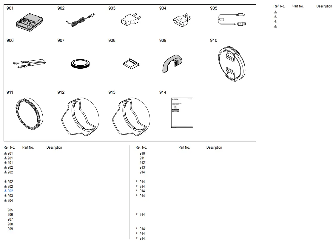
ACCESSORIES
![]()
![Sony Α7c Interchangeable Lens Digital Camera [ilce-7c] User Manual](https://static-data1.manualsee.com/1/img/50/16967/2020/12/00-8.jpg "Sony Α7c Interchangeable Lens Digital Camera [ilce-7c] User Manual")


