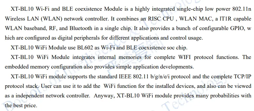
Shenzhen Sibo Zhilian Technology XT-BL10 Bluetooth Wi-Fi 2.4 Module
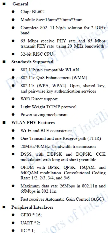
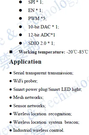
FEATURES

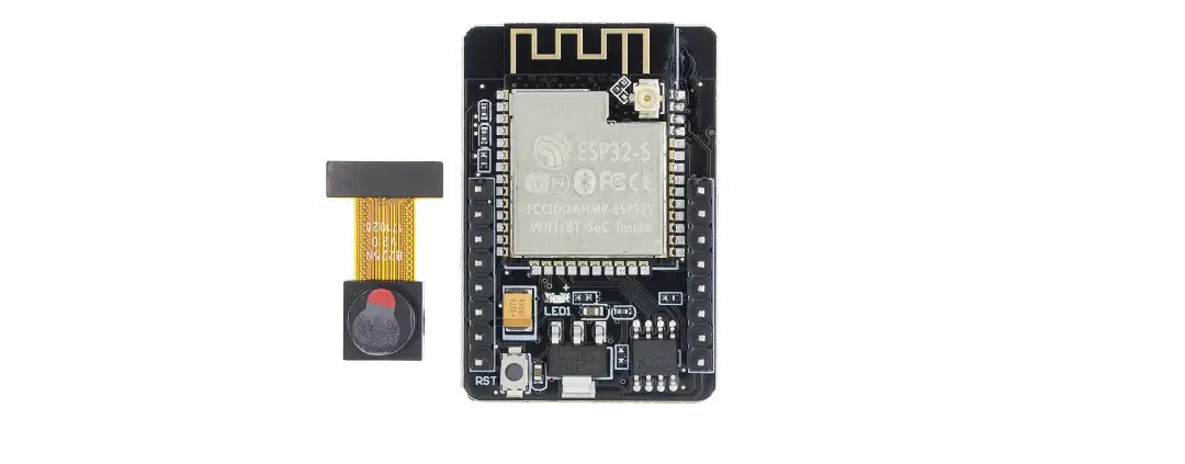
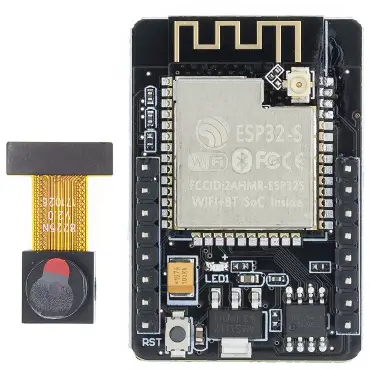
MODAL STRUCTURE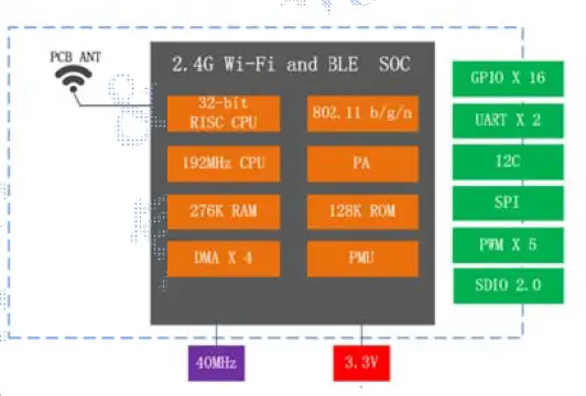
MODAL STRUCTURE

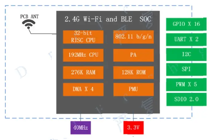
Technical parameters for XT-BL10 are listed as follows.
| Types | Items | Parameters |
|
Wi-Fi | Frequency | 2.4G~2.5G(2400M~2483.5M) |
|
Transmit power | 802.11b: 19 ±1dBm | |
| 802.11g: 19 ±1dBm | ||
| 802.11n: 19 ±1dBm | ||
|
Receiver sensitivity | 802.11b: -91 dbm (11Mbps) | |
| 802.11g: -77 dbm(54Mbps) | ||
| 802.11n: -73 dbm(MCS7) | ||
| EVM | <-28dB @802.11g | |
| <-28dB @802.11n | ||
| Antenna | PCB antenna | |
|
Hardware | CPU | 32-bit RISC CPU |
| Interface | UART/SDIO/SPI/I2C/GPIO/PWM | |
| Working voltage | 3.0V ~ 3.6V | |
|
Working current | Deep Sleep Mode:15uA | |
| Deep Standby Mode:2mA | ||
| Average: 120mA | ||
| Working temperature | -30°C ~85°C | |
| Environment temperature | -30°C ~ 105°C | |
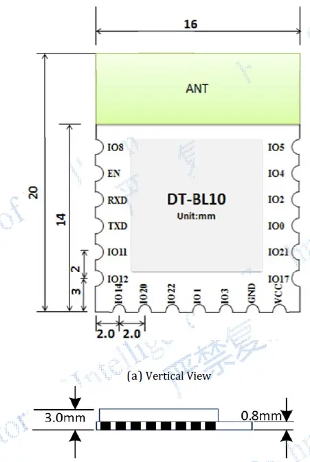
| Shape | 16mm x 20mm x 3mm | |
|
Software | Wi-Fi working mode | STA, SoftAP and sniffer modes |
| Security mode | WPS / WEP / WPA / WPA2 / WPA3 | |
| Encryption type | AES | |
| Update firmware | UART Download | |
| Software develop | SDK | |
| Network protocol | IPv4, TCP/UDP/HTTP/FTP/MQTT |
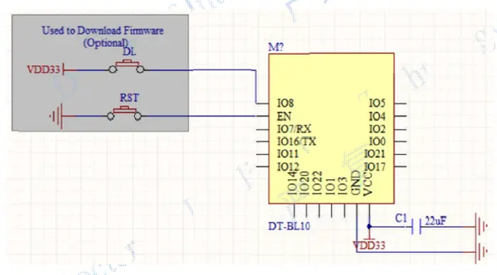
INTERFACE DEFINATION
XT-BLL 10 modul ee interface dd efinition is shown as b elow。 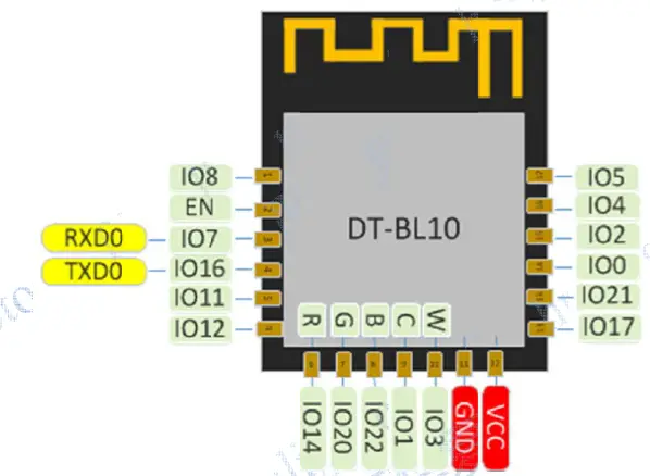
Working mode and pin function
| Mode | GPIO8 |
| UART Download Mode | High |
| Flash Boot Mode | Low |
| Num | Pin Name | Type | Function |
| 1 | GPIO8 | I/O | SPI, I2C, UART, PWM, AUXADC, GPIO. |
| 2 | EN | I/O | Chip enable |
| 3 | GPIO7 | I/O | SPI, I2C, UART, PWM, GPIO |
| 4 | GPIO16 | I/O | SPI, I2C, UART, PWM, GPIO |
| 5 | GPIO11 | I/O | SPI, I2C, UART, PWM, AUXADC, GPIO,*Low-High when Reset |
| 6 | GPIO12 | I/O | SPI, I2C, UART, PWM, AUXADC, GPIO |
| 7 | GPIO14 | I/O | SPI, I2C, UART, PWM, AUXADC, GPIO |
| 8 | GPIO20 | I/O | SFLASH, SPI, I2C, UART, PWM, GPIO |
| 9 | GPIO22 | I/O | SFLASH, SPI, I2C, UART, PWM, GPIO |
| 10 | GPIO1 | I/O | SDIO, SFLASH, SPI, I2C, UART, PWM, GPIO |
| 11 | GPIO3 | I/O | SDIO, SPI, I2C, UART, PWM, GPIO |
| 12 | GND | P | Power |
| 13 | VDD33 | P | Power |
| 14 | GPIO17 | I/O | SFLASH, SPI, I2C, UART, PWM, GPIO |
| 15 | GPIO21 | I/O | SFLASH, SPI, I2C, UART, PWM, GPIO |
| 16 | GPIO0 | I/O | SDIO, SFLASH, SPI, I2C, UART, PWM, GPIO |
| 17 | GPIO2 | I/O | SDIO, SFLASH, SPI, I2C, UART, PWM, GPIO |
| 18 | GPIO4 | I/O | SDIO, SPI, I2C, UART, PWM, GPIO |
| 19 | GPIO5 | I/O | SDIO, SPI, I2C, UART, PWM, GPIO |
SIZE AND LAYOUT
Size for d Layocan be show AS follows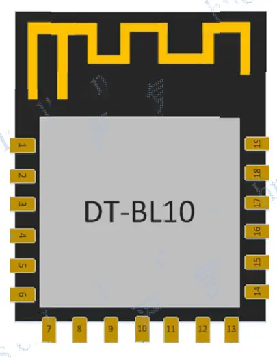
Electronic Characteristic
| Parameters | Condition | Min | Classical | Max | Unite | |
| Store Temperature | – | -30 | Normal | 155 | ℃ | |
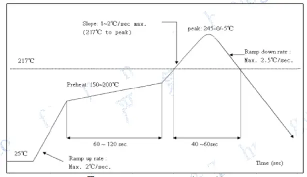
| Sold Temperature | IPC/JEDEC J- STD-020 | – | – | 260 | ℃ | |
| Working Voltage | – | 2.5 | 3.3 | 3.6 | V | |
| I/O | VIL/VIH | – | -/2.0 | – | 0.8/- | V |
| VOL/VOH | – | -/2.4 | – | 0.4/- | ||
| Electrostatic release quantity (Human model) | TAMB=25℃ | – | – | 2 | KV | |
| Electrostatic release quantity (Human model) | TAMB=25℃ | – | – | 0.5 | KV | |
Power Consumption
| Parameters | Min | Classical | Max | Unit |
| RX 11b | – | 35 | – | mA |
| RX 11g | 39 |
| RX 11n | 39 | |||
| TX(11b – 11Mbps @20dBm) | – | 310 | – | mA |
| TX(11g – 54Mbps@18dBm) | – | 230 | – | mA |
| TX(11n – MCS7@17dBm) | – | 215 | – | mA |
| MCU(Run Freq@ 192MHz) | – | 22 | – | mA |
| MCU(Standby Freq@<10MHz) | – | 2 | – | mA |
RF Characteristic
| Parameters | Min | Classical | Max | Unite |
| Input frequencey | 2412 | – | 2462 | MHz |
| Input impedance | – | 50 | – | Ω |
| Input reflection | – | – | -10 | dB |
| At 11b mode, output power consumption | – | 18 | – | dBm |
| At 11g mode, output power consumption | – | 19 | – | dBm |
| At 11n mode, output power consumption | – | 18 | – | dBm |
| Sensibility | – | – | – | – |
| 802.11b, 1Mbps | – | -98 | – | dBm |
| 802.11g, 64Mbps | – | -93 | – | dBm |
| 802.11n, MCS7 | – | -73 | – | dBm |
The Recomended Sold Temprature Curve
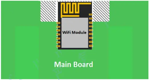
Minimum User System
This modul can work working volt just at 3.3V working voltage
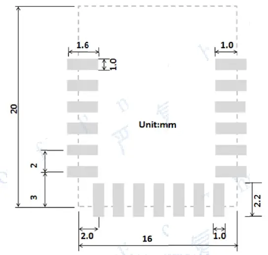
The Recomended PCB Design


FCC WARNING
FCC Caution: Any changes or modifications not expressly approved by the party responsible for compliance could void the user’ authority to operate this equipment. This device complies with Part 15 of the FCC Rules.
Operation is subject to the following two conditions:
- This device may not
cause harmful interference, and - this device must accept any interference received, including interference that may cause undesired operation.
This device and its antenna- must not be co-located or operating in conjunction with any other antenna or transmitter. 15.105 Information to the user.
- For a Class B digital device or peripheral, the instructions furnished the user shall include the following or similar statement, placed in a prominent location in the text of the manual:
Note: This equipment has been tested and found to comply with the limits for a Class B digital device, pursuant to part 15 of the FCC Rules. These limits are designed to provide reasonable protection against harmful interference in a residential installation. This equipment generates, uses and can radiate radio frequency energy and, if not installed and used in accordance with the instructions, may cause harmful interference to radio communications. However, there is no guarantee that interference will not occur in a particular installation. If this equipment does cause harmful interference to radio or television reception, which can be determined by turning the equipment off and on, the user is encouraged to try to correct the interference by one or more of the following measures: - Reorient or relocate the receiving antenna.
- Increase the separation between the equipment and receiver.
- Connect the equipment into an outlet on a circuit different from that to which m,the receiver is connected.
- Consult the dealer or an experienced radio/TV technician for help.
This equipment complies with FCC radiation exposure limits set forth for an uncon- trolled environment. This equipment should be installed and operated with minimum distance 20 cm between the radiator and your body.
Radiation Exposure Statement:
- This equipment complies with FCC radiation exposure limits set forth for an uncontrolled environment.
- This transmitter must not be co-located or operating in conjunction with any other antenna or transmitter.
- The availability of some specific channels and/or operational frequency bands are country dependent and are firmware programmed at the factory to match the intended destination.
- The firmware setting is not accessible by the end user.
The final end product must be labelled in a visible area with the following:
“Contains Transmitter Module “2A3UG-XT-BL10”
Requirement per KDB996369 D03
List of applicable FCC rules
List the FCC rules that are applicable to the modular transmitter. These are the rules that specifically establish the bands of operation, the power, spurious emissions, and operating fundamental frequencies. DO NOT list compliance to unintentional-radiator rules (Part 15 Subpart B) since that is not a condition of a module grant that is extended to a host manufacturer. See also Section 2.10 below concerning the need to notify host manufacturers that further testing is required.3
Explanation:
- This module meets the requirements of FCC part 15C (15.247).it Specifically identified AC Power Line Conducted Emission, Radiated Spurious emissions, Band edge and RF Conducted Spurious Emissions, Conducted Peak Output Power, Bandwidth, Power Spectral Density, Antenna Requirement.
Summarize the specific operational use conditions
Describe use conditions that are applicable to the modular transmitter, including for example any limits on antennas, etc. For example, if point-to- point antennas are used that require reduction in power or compensation for cable loss, then this information must be in the instructions. If the use condition limitations extend to professional users, then instructions must state that this information also extends to the host manufacturer’s instruction manual. In addition, certain information may also be needed, such as peak gain per frequency band and minimum gain, specifically for master devices in 5 GHz DFS bands. - The EUT has one PCB Antenna, the antenna can be replaced by other authorized antennas, and the gain of each replacement antenna is no more than 1.0dBi
Limited module procedures
If a modular transmitter is approved as a “limited module,” then the module manufacturer isresponsible for approving the host environment that the limited module is used with. The manufacturer of a limited module must describe, both in the filing and in the installation instructions, the alternative means that the limited module manufacturer uses to verify that the host meets the necessary requirements to satisfy the module limiting conditions. A limited module manufacturer has the flexibility to define its alternative method to address the conditions that limit the initial approval, such as: shielding, minimum signaling amplitude, buffered modulation/data inputs, or power supply regulation. The alternative method could include that the limited The module manufacturers shall provide a list of acceptable unique connectors.
Explanation: The EUT has one PCB Antenna, the antenna can be replaced by other authorized antennas, and the gain of each replacement antenna is no more than 1.0dBi
Label and compliance information
Grantees are responsible for the continued compliance of their modules to the FCC rules. This
includes advising host product manufacturers that they need to provide a physical or e-label stating “Contains FCC ID” with their finished product. See Guidelines for Labeling and User Information for RF Devices – KDB Publication 784748.
Explanation:
- The host system using this module, should have label in a visible area indicated the following texts: “Contains FCC ID: 2A3UG-XT-BL10.
Information on test modes and additional testing requirements5
Additional guidance for testing host products is given in KDB Publication 996369 D04 Module Integration Guide. Test modes should take into consideration different operational conditions for a stand-alone modular transmitter in a host, as well as for multiple simultaneously transmitting modules or other transmitters in a host product.
The grantee should provide information on how to configure test modes for host product evaluation for different operational conditions for a stand-alone modular transmitter in a host, versus with multiple, simultaneously transmitting modules or other transmitters in a host.
Grantees can increase the utility of their modular transmitters by providing special means, modes, or instructions that simulates or characterizes a connection by enabling a transmitter. This can greatly simplify a host manufacturer’s determination that a module as installed in a host complies with FCC requirements. - Shenzhen Sibo Zhilian Technology Co., Ltd. can increase the utility of our modular transmitters by providing instructions that simulates or characterizes a connection by enabling a transmitter
Additional testing, Part 15 Subpart B disclaimer
The grantee should include a statement that the modular transmitter is only FCC authorized for the specific rule parts (i.e., FCC transmitter rules) listed on the grant, and that the host product manufacturer is responsible for compliance to any other FCC rules that apply to the host not covered by the modular transmitter grant of certification. If the grantee markets their product as being Part 15 Subpart B compliant (when it also contains unintentional-radiator digital circuity), then the grantee shall provide a notice stating that the final host product still requires Part 15 Subpart B compliance testing with the modular transmitter installed.
- The module without unintentional-radiator digital circuity, so the module does not require an evaluation by FCC Part 15 Subpart B. The host shoule be evaluated by the FCC Subpart B.


