![]() Rakwireless Technology RAK13401 Bluetooth Module Datasheet
Rakwireless Technology RAK13401 Bluetooth Module Datasheet
User Manual
Overview
Description
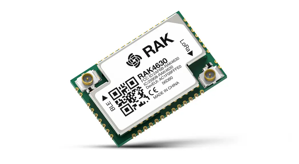
The RAK13401 is a highly integrated Bluetooth 5 module with a UART (Universal Asynchronous Receiver/Transmitter) interface. The module is designed based on EM9304V01 LF28B from EM Microelectronic and has BT Protocol Stack, BT Baseband, modem and BT RF in a single module. The RAK13401 provides a low-power and ultra- low-cost BLE solution for wireless transmission applications. It can be used in conjunction with other products from Rakwirekess like RAK7268C to achieve more applications.
Features
- Bluetooth 5 specification compliant
- Supports Bluetooth Low Energy (BLE)
Maximum output power: 6.2dBm - Receive sensitivity: -94 dBm(BLE Minimum)
- HS-UART interface for Bluetooth data transmission compliant HS specification
- Support rate: 1Mb/s(LE 1 M)
- Typical Antenna Peak Gain: 1.8 dBi (@2442MHz)
- Supply voltage: 1.9 to 3.63V
- Temperature range:-40 C to +85 ·€
- Module size:20mmx30mm
Specifications
Overview
Mounting
The RAK13401 Bluetooth module can be mounted to a board which have a standard Wiscore slot.
Figure 1 shows the mounting mechanism of the RAK13401 on a RAK7268C. 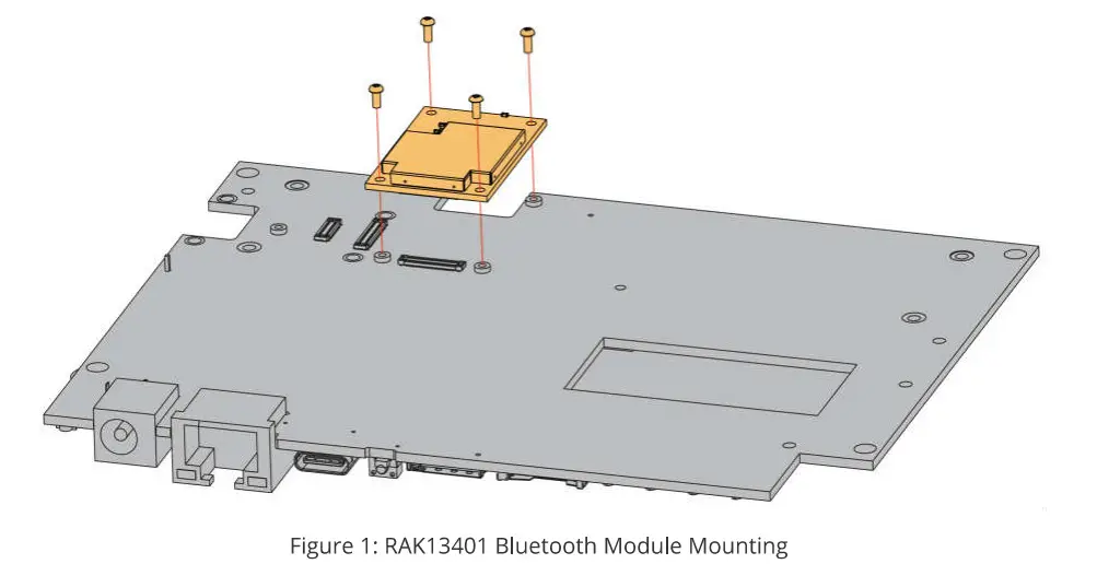
Pin Definition
The RAK13401 Bluetooth module comprises a standard Wiscore connector, The Wiscore connector allows the RAK13401 module to be mounted to a board that has a standard Wiscore slot such as RAK7268. The pin order of the connector and the pinout definition is shown in Figure 2
NOTE
UART-related pin, RESET,3V3, and GND are connected to the Wiscore connector 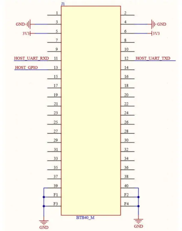
Electrical Characteristics
Absolute Maximum Ratings
| Parameter | Minimum | Maximum | Unit |
| Operating voltage | 1.9 | 3.63 | V |
| Maximum output power | – | 6.2 | dBM |
| Receive sensitivity | -94 | – | dBM |
| Temperature range | -40 | 85 | ºC |
| ESD | -2 | 2 | kv |
Mechanical Characteristic
Board Dimensions
Figure 3 shows the dimensions and the mechanical drawing of the RAK13401module 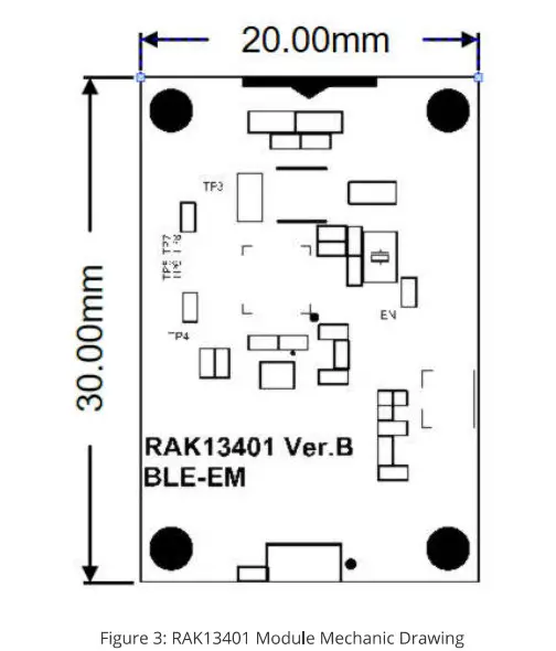
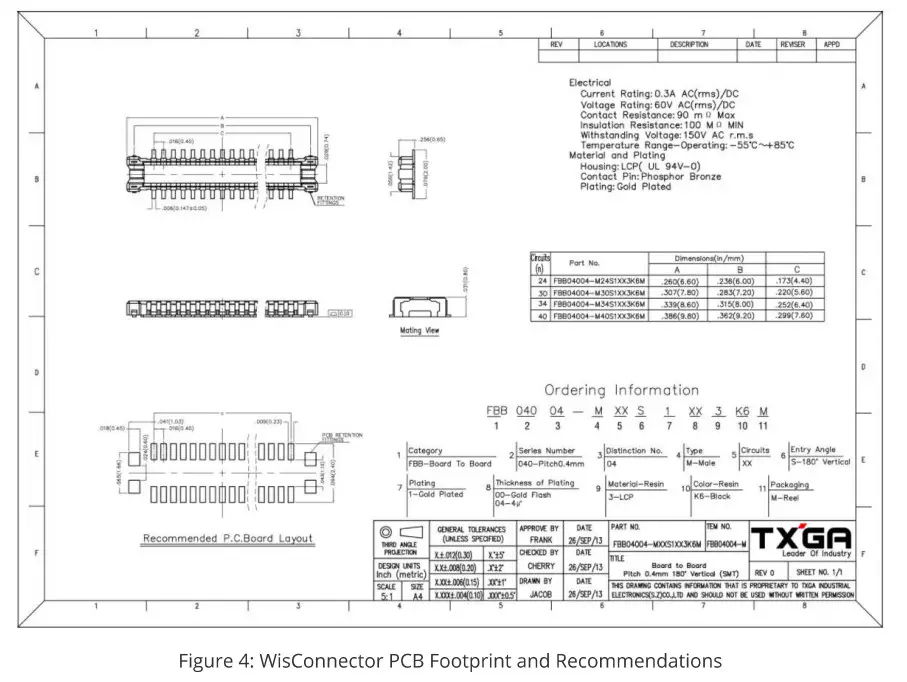
WisConnector PCB Layout
Schematic
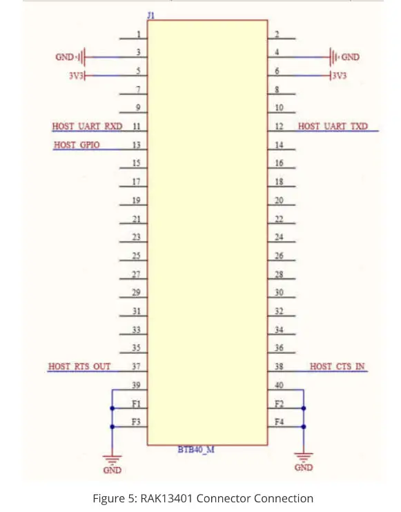
Connector
Figure 5 shows the connector connection. UART-related pin, RESET,3V3, and GND are connected to the connector. Serial port hardware (CTS and RTS) control is not applicable by default.
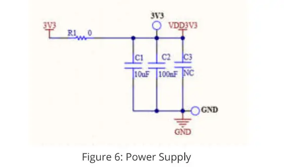
Power Supply
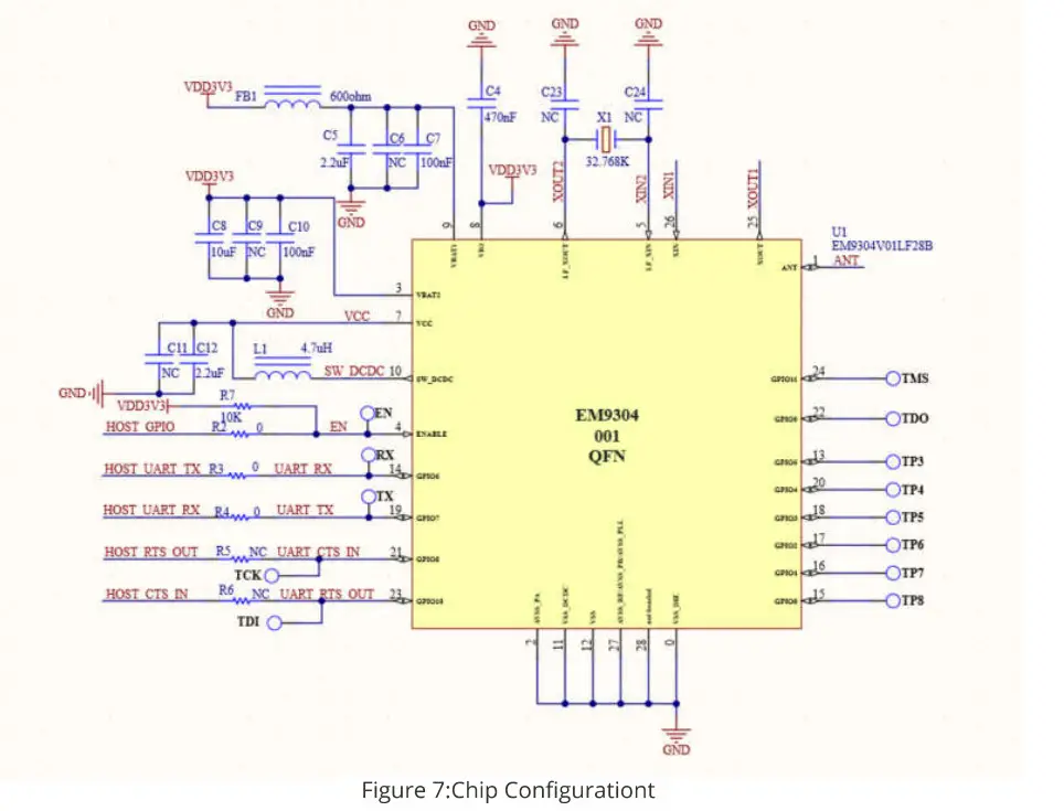
Chip Configuration
Antenna matching circuit
The onboard ceramic antenna is used by default. 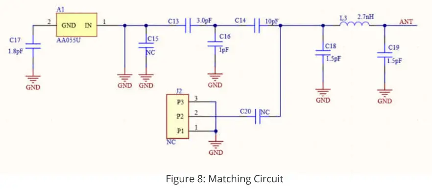
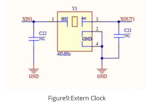
Extern Clock
History
| Date | Version | Description |
| 2021 12-1 | V1.0 | Initial |
Statement
This device complies with Part 15 of the FCC Rules. Operation is subject to the following two conditions: (1) this device may not cause harmful interference, and (2) this device must accept any interference received, including interference that may cause undesired operation.
FCC Caution:
Changes or modifications not expressly approved by the party responsible for compliance could void the user’s authority to operate the equipment.
FCC RF Radiation Exposure Statement Caution: This Transmitter must be installed to provide a separation distance of at least 20 cm from all persons.
FCC Statement:
“This equipment has been tested and found to comply with the limits for a Class B digital device, pursuant to part 15 of the FCC Rules. These limits are designed to provide reasonable protection against harmful interference in a residential installation. This equipment generates, uses, and can radiate radio frequency energy and, if not installed and used in accordance with the instructions, may cause harmful interference to radio communications. However, there is no guarantee that interference will not occur in a particular installation. If this equipment does cause harmful interference to radio or television reception, which can be determined by turning the equipment off and on, the user is encouraged to try to correct the interference by one or more of the following measures:
- Reorient or relocate the receiving antenna.
- Increase the separation between the equipment and receiver.
- Connect the equipment into an outlet on a circuit different from that to which the receiver is connected.
- Consult the dealer or an experienced radio/TV technician for help.”
IC statement:
This device complies with Industry Canada licence-exempt RSS standard(s).
Operation is subject to the following two conditions: (1) this device may not cause interference, and (2) this device must accept any interference, including interference that may cause undesired operation of the device.
This equipment complies with Industry Canada radiation exposure limits set forth with a separation The proposed FCC IC label format is to be placed on the module. If it is not visible when the module is installed into the system, “Contains FCC ID: 2AF6B-RAK13401, Contains IC: 25908-RAK13401” shall be placed on the outside of the final host system.
Labeling
- This radio transmitter [25908-RAK13401] has been approved by Innovation, Science and Economic Development Canada to operate with the ceramic chip antenna, with the maximum permissible gain 2.3dBi. Antennas of that same type greater than the maximum gain are strictly prohibited for use with this device.
www.RAKwireless.com
Copyright Shenzhen AKwireless Technology Co. Ltd


