![]() N1040 Controller
N1040 Controller
 TEMPERATURE CONTROLLER – USER GUIDE – V2.2x
SAFETY ALERTS
The symbols below are used on the equipment and throughout this document to draw the user’s attention to important operational and safety information.
 |  |
| CAUTION: Read the manual thoroughly before installing and operating the equipment. | CAUTION OR DANGER: Electrical shock hazard. |
All safety related instructions that appear in the manual must be observed to ensure personal safety and to prevent damage to either the instrument or the system. If the instrument is used in a manner not specified by the manufacturer, the protection provided by the equipment may be impaired.
INSTALLATION / CONNECTIONS
The controller must be fastened on a panel, following the sequence of steps described below:
- Prepare a panel cut-out according to SPECIFICATIONS.
- Remove the mounting clamps from the controller.
- Insert the controller into the panel cut-out.
- Slide the mounting clamp from the rear to a firm grip at the panel.
ELECTRICAL CONNECTIONS
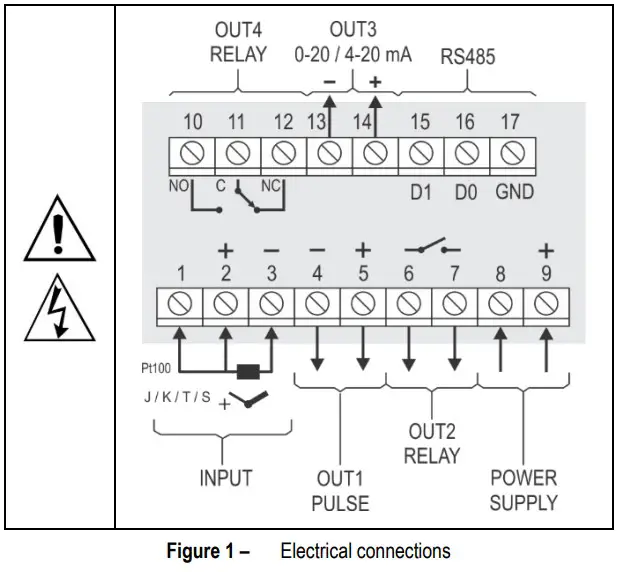
Figure 1 below shows the electrical terminals of the controller:
INSTALLATION RECOMMENDATIONS
- All electrical connections are made to the screw terminals at the rear of the controller.
- To minimize the pick-up of electrical noise, the low voltage DC connections and the sensor input wiring should be routed away from high-current power conductors. If this is impractical, use shielded cables. In general, keep cable lengths to a minimum.
- All electronic instruments must be powered by a clean mains supply, proper for instrumentation.
- It is strongly recommended to apply RC’S FILTERS (noise suppressor) to contactor coils, solenoids, etc. In any application it is essential to consider what can happen when any part of the system fails. The controller features by themselves cannot assure total protection.
FEATURES
INPUT TYPE SELECTION
Table 1 shows the sensor types accepted and their respective codes and ranges. Access the parameter TYPE in the INPUT cycle to select the appropriate sensor.
| TYPE | CODE | MEASUREMENT RANGE |
| Thermocouple J | Range: -110 to 950 °C (-166 to 1742 °F) | |
| Thermocouple K | Range: -150 to 1370 °C (-238 to 2498 °F) | |
| Thermocouple T | Range: -160 to 400 °C (-256 to 752 °F) | |
| Pt100 | Range: -200 to 850 °C (-328 to 1562 °F) |
Table 1 – Input types
OUTPUTS
The controller offers two, three or four output channels, depending on the loaded optional features. The output channels are user configurable as Control Output, Alarm 1 Output, Alarm 2 Output, Alarm 1 OR Alarm 2 Output, and LBD (Loop Break Detect) Output.
| OUTPUT OUT1 | Pulse type output of electrical voltage. 5 Vdc / 50 mA max. Available on terminals 4 and 5. |
| OUTPUT OUT2 | SPST-NO relay. Available on terminals 6 and 7. |
| OUTPUT OUT3 | SPST-NO relay. Available on terminals 13 and 14 (PRRR Model). Analog Output or Current Output. 0-20 / 4-20 mA, 500 R max. Available on terminals 13 and 14 (PRAR model). |
| OUTPUT OUT4 | SPDT relay. Available on terminals 10, 11, and 12. |
CONTROL OUTPUT
It is the output that will command the process actuator (heating resistor, cooling compressor, etc.). The control output can be directed to a relay, an analog output, or even a Pulse type Electrical Voltage output, according to availability.
CONTROL MODE
The controller has two modes: Manual Mode or Automatic Mode. The ![]() parameter allows you to select one or the other control mode.
parameter allows you to select one or the other control mode.
In Manual mode (![]() ), you determine the MV value applied to the Control Output.
), you determine the MV value applied to the Control Output.
In Automatic mode (![]() ), the controller is in control of the process, automatically setting the MV value to be applied to the output defined as the Control Output.
), the controller is in control of the process, automatically setting the MV value to be applied to the output defined as the Control Output.
In Automatic mode there are two distinct control strategies: ON/OFF Control and PID Control.
The ON/OFF Control, obtained when you set the Proportional Band (![]() ) parameter to 0.0, acts on the Control Output, based on the simple relation between SP and PV (measured temperature).
) parameter to 0.0, acts on the Control Output, based on the simple relation between SP and PV (measured temperature).
The PID Control action is based on a mathematical control algorithm, which, considering the correlation between SP and PV, acts on the Control Output and on the values set for parameters ![]() ,
, ![]() , and
, and ![]() .
.
The determination of parameters ![]() ,
, ![]() , and
, and ![]() is described in the PID PARAMETERS DEFINITION section
is described in the PID PARAMETERS DEFINITION section
ANALOG OUTPUT OR CURRENT OUTPUT
The controller has an analog output of electric current that can perform the following functions:
– Process control output
– Process PV retransmission output
– Process SP retransmission output
As a control output, it relates the MV range (0 to 100 %) to the current range: 4 to 20 mA or 0 to 20 mA.
0 % MV determines 4 mA (or 0 mA) on the Analog Output 100 % MV determines 20 mA on the Analog Output
As the PV / SP relay output of the process, the electrical current applied to the analog output will be proportional to the ratio between the value of the variable (PV or SP) and the retransmission range defined by parameters ![]() and
and ![]() .
.
The analog output is electrically isolated from the other controller circuits.
It has a measurement accuracy of 0.25 % of the Operating Range or 0.4 mA.
ALARM OUTPUT
The controller contains 2 alarms that can be directed (assigned) to any output channel. The alarm functions are described in Table 2.
| Output is not used as alarm. | ||
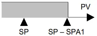
| Alarm of absolute minimum value. Triggers when the value of measured PV is below the value defined for alarm Setpoint. (SPA1 or SPA2). | 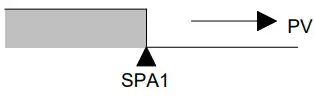 | |
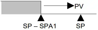
| Alarm of absolute maximum value. Triggers when the value of measured PV is above the value defined for alarm Setpoint. | 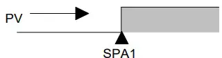 | |
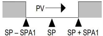
| Alarm of differential value. In this function the parameters SP 1 and SP 2 represent the deviation of PV in relation to the SP of | ||
| CONTROL. | ||
 |  | |
| Positive SPA1 | Negative SPA1 | |
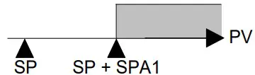
| Alarm of minimum differential value. It triggers when the value of PV is below the defined point by (using the Alarm 1 as example). | ||
 |  | |
| Positive SPA1 | Negative SPA1 | |
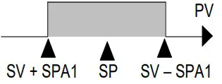
| Alarm of valor maximum differential value. Triggers when the value of PV is above the defined point by (using Alarm 1 as example): | ||
 | 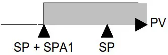 | |
| Positive SPA1 | Negative SPA1 | |
| Alarms of the Sensor Break (Sensor Break Alarm). It is activated when the Input presents problems such as interrupted sensor, bad connection, etc. | ||
Table 2 – Alarm functions
Note: Alarm functions on Table 02 are also valid for Alarm 2 (SPA2).
Important note: Alarms configured with the ![]() ,
, ![]() and
and ![]() functions also trigger their associated output when a sensor fault is identified and signaled by the controller. A relay output, for example, configured to act as a High Alarm (
functions also trigger their associated output when a sensor fault is identified and signaled by the controller. A relay output, for example, configured to act as a High Alarm (![]() ), will operate when the SPAL value is exceeded and when the sensor connected to the controller input is broken.
), will operate when the SPAL value is exceeded and when the sensor connected to the controller input is broken.
INITIAL BLOCKING OF ALARM
The Initial Blocking option inhibits the alarm from being recognized if an alarm condition is present when the controller is first energized.
The alarm will be enabled only after the occurrence of a non-alarm condition.
The initial blocking is useful, for example, when one of the alarms is configured as a minimum value alarm, causing the activation of the alarm soon upon the process start-up, an occurrence that may be undesirable.
The initial blocking is disabled for the sensor break alarm function ![]() (Open sensor).
(Open sensor).
SAFE OUTPUT VALUE WITH SENSOR FAILURE
Function that places the control output in a safe condition for the process when is identified an error in the sensor input.
With a fault identified in the sensor, the controller determines the percentage value defined in parameter ![]() for the control output.
for the control output.
The controller will remain in this condition until the sensor failure disappears. ![]() values are only 0 and 100 % when in ON/OFF control mode. For PID control mode, any value in the range from 0 to 100 % is accepted.
values are only 0 and 100 % when in ON/OFF control mode. For PID control mode, any value in the range from 0 to 100 % is accepted.
LBD FUNCTION – LOOP BREAK DETECTION
The ![]() parameter allows you to set a maximum time interval (in minutes) for the process temperature (PV) to react to the command from the control output. If the PV does not react properly within the time interval configured, the controller signals in its display the occurrence of the LBD event, which indicates problems in the control loop.
parameter allows you to set a maximum time interval (in minutes) for the process temperature (PV) to react to the command from the control output. If the PV does not react properly within the time interval configured, the controller signals in its display the occurrence of the LBD event, which indicates problems in the control loop.
The LBD event can also be sent to one of the output channels of the controller. To do this, simply configure the desired output channel with the ![]() function which, in the event of this event, is triggered.
function which, in the event of this event, is triggered.
This function is disabled with value 0 (zero).
This function allows the user to detect problems in the installation, such as defective actuators, power supply failure, etc.
OFFSET
Feature that allows the user to make small adjustment in the temperature indication. Allows correcting measurement differences that appear, for example, when replacing the temperature sensor.
USB INTERFACE
The USB interface is used to CONFIGURE, MONITOR or UPDATE the controller FIRMWARE. The user should use Quick Tune software, which offers features to create, view, save and open settings from the device or files on the computer. The tool for saving and opening configurations in files allows the user to transfer settings between devices and perform backup copies.
For specific models, Quick Tune allows to update the firmware (internal software) of the controller via the USB interface.
For MONITORING purposes, the user can use any supervisory software (SCADA) or laboratory software that supports the MODBUS RTU communication over a serial communication port. When connected to a computer’s USB, the controller is recognized as a conventional serial port (COM x).
The user must use Quick Tune software or consult the DEVICE MANAGER on the Windows Control Panel to identify the COM port assigned to the controller.
The user should consult the mapping of the MODBUS memory in the controller’s communication manual and the documentation of the supervision software to start the MONITORING process.
Follow the procedure below to use the USB communication of the device:
- Download Quick Tune software from our website and install it on the computer. The USB drivers necessary for operating the communication will be installed with the software.
- Connect the USB cable between the device and the computer. The controller does not have to be connected to a power supply. The USB will provide enough power to operate the communication (other device functions may not operate).
- Run the Quick Tune software, configure the communication and start the device recognition.
| The USB interface IS NOT SEPARATE from the signal input (PV) or the controller’s digital inputs and outputs. It is intended for temporary use during CONFIGURATION and MONITORING periods. For the safety of people and equipment, it must only be used when the piece of equipment is completely disconnected from the input/output signals. Using the USB in any other type of connection is possible but requires a careful analysis by the person responsible for installing it. When MONITORING for prolonged periods of time and with connected inputs and outputs, we recommend using the RS485 interface. |
OPERATION
The front panel can be seen in Figure 2:
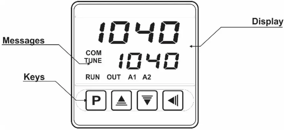
Figure 2 – Identification of the parts referring to the front panel
Display: Displays the measured variable, symbols of the configuration parameters and their respective values/conditions.
COM Indicator: Flashes to indicate communication activity in the RS485 interface.
TUNE Indicator: Stays ON while the controller is in tuning process.
OUT Indicator: For relay or pulse control output; it reflects the actual state of the output.
A1 and A2 Indicators: Signalize the occurrence of alarm situation.
P Key: Used to walk through the menu parameters.![]() Increment key and
Increment key and ![]() Decrement key: Allow altering the values of the parameters.
Decrement key: Allow altering the values of the parameters.![]() Back key: Used to retrocede parameters.
Back key: Used to retrocede parameters.
STARTUP
When the controller is powered up, it displays its firmware version for 3 seconds, after which the controller starts normal operation. The value of PV and SP is then displayed, and the outputs are enabled.
For the controller to operate properly in a process, its parameters need to be configured first, such that it can perform accordingly to the system requirements. The user must be aware of the importance of each parameter and for each one determines a valid condition.
The parameters are grouped in cycles, according to their functionality and operation easiness. The 5 cycles of parameters are: 1 – Operation / 2 – Tuning / 3 – Alarms / 4 – Input / 5 – Calibration
The P key is used for accessing the parameters within a cycle.
Keeping the P key pressed, at every 2 seconds the controller jumps to the next cycle of parameters, showing the first parameter of each cycle:
![]()
To enter a particular cycle, simply release the P key when the first parameter in that cycle is displayed. To walk through the parameters in a cycle, press the P key with short strokes. To go back to the previous parameter in a cycle, press![]() .
.
Each parameter is displayed with its prompt in the upper display and value/condition in the lower display. Depending on the level of parameter protection adopted, the parameter PASS precedes the first parameter in the cycle where the protection becomes active. See section CONFIGURATION PROTECTION.
PARAMETER DESCRIPTION
OPERATION CYCLE
PV + SP | PV Indication screen. On the higher display (red) the value of the measured variable (PV) temperature is shown. On the lower display (green), the control Setpoint (SP) is shown. |
| Alarm SP. Value that defines the alarm activation point. For the alarms set up with the Differential functions, these parameters define deviations. This parameter is not used for the alarm function Parameters shown in this cycle only when enabled in the parameters |
TUNING CYCLE
| AUTO-TUNE. Enables the auto-tuning function for the PID parameters. Defines the control strategy to be taken:
| |
| Proportional Band. Value of the term P of the control mode PID, in percentage of the maximum span of the input type. Adjust of between 0 and 500.0 %. When set to zero (0), control action is ON/OFF. | |
| Integral Rate. Value of the term I of the PID algorithm, in repetitions per minute (Reset). Adjustable between 0 and 24.00. Displayed only if proportional band ¹ 0. | |
| Derivative Time. Value of the term D of the control mode PID, in seconds. Adjustable between 0 and 250.0 seconds. Displayed only if proportional band ¹ 0. | |
| Cycle time. Pulse Width Modulation (PWM) period in seconds. Adjustable between 0.5 and 100.0 seconds. Displayed only if proportional band ¹ 0. | |
| Hysteresis. Is the hysteresis for ON/OFF control (set in temperature units). This parameter is only used when the controller is in ON/OFF mode (Pb=0). | |
| Action control: | |
| Soft Start Function. Time interval, in seconds, while the controller limits the control output (MV) rising rate. (Zero value disables the Soft Start function). | |
| Assign functions to the Output channels OUT1, OUT2, OUT3, and OUT4: |
| On controller models with the analog output feature, the OUT3 configuration options are: off Non-used output. |
ALARMS CYCLE
| Alarm functions. Defines the functions for the alarms among the options of the Table 2. | |
| Alarm SP. Value that defines the point of activation of the alarm outputs. For the alarms programmed with the Differential functions, these parameters represent the deviations. This parameter is not used for the alarm function :Err. | |
| SP Enable. Configures display of SPA1 and SPA2 also in the Operation Cycle. | |
| Blocking alarms. | |
| Alarm hysteresis. Defines the difference between the value of PV at which the alarm is triggered and the value at which it is turned off. | |
| Allows visual signalization of an alarm occurrence by flashing the indication of PV in the Operation Cycle. |
INPUT CYCLE
| Input Type. Selects the input signal type to be connected to the process variable input. Refer to Table 1 for the available options. (J) (K) (T) (Pt100) | |
| Digital Input Filter. Used to improve the stability of the measured signal (PV). Adjustable between 0 and 20. In 0 (zero) it means filter turned off and 20 means maximum filter. The higher the filter value, the slower is the response of the measured value. | |
| Selects the decimal point position to be viewed in both PV and SP. |
| Selects display indication for degrees Celsius or Fahrenheit: | |
| Offset value to be added to the PV reading to compensate sensor error. Default value: Zero. | |
| SP Low Limit. Defines the SP lower limit of. | |
| SP High Limit. Defines the upper limit for adjustment of SP. | |
| Retransmission Low Limit. Allows you to set the lower limit of the SP or PV retransmission range on OUT3. Parameter displayed only when selecting one of the Retransmit functions available for the Analog Output. | |
| Retransmission High Limit. Allows you to set the upper limit of the SP or PV retransmission range on OUT3. Parameter displayed only when selecting one of the Retransmission functions available for the Analog Output. | |
| Loop Break Detection Time. Time interval for the LBD function. Defines the maximum interval of time for the PV to react to a control command. In minutes. | |
| Percentage value to be applied to the output on any failure of the sensor that is connected to the controller input. | |
| Digital communication Baud Rate selection. In kbps with the following speeds available: 1.2, 2.4, 4.8, 9.6, 19.2, 38.4, 57.6, and 115.2. Parameter shown only on models with serial communication. | |
| Parity of the serial communication. Parameter shown only on models with serial communication. | |
| Communication address. Number that identifies the controller in the serial communication network, between 1 and 247. Parameter shown only on models with serial communication. |
CALIBRATION CYCLE
All types of input are calibrated in the factory. In case a recalibration is required; it shall be carried out by a specialized professional. In case this cycle is accidentally accessed, do not perform alteration in its parameters.
| Password. This parameter is presented before the protected cycles. See item Protection of Configuration. | |
| Calibration. Enables the possibility for calibration of the indicator. When the calibration is not enabled, the related parameters are hidden. | |
| Input Low Calibration. Enter the value corresponding to the low scale signal applied to the analog input. |
| Input High Calibration. Enter the value corresponding to the full-scale signal applied to the analog input. | |
| Analog Output Low Calibration. Analog Output (AO) user calibration. Declaration of the electrical current value present at the analog output. Low point adjustments. See MAINTENANCE chapter. | |
| Analog Output High Calibration. Analog Output (AO) user calibration. Declaration of the electrical current value present at the analog output. High point adjustments. See MAINTENANCE chapter. | |
| Restore. Restores the factory calibration for all inputs and outputs, disregarding modifications carried out by the user. | |
| Cold Junction. This screen is for information purpose only. | |
| Password Change. Allows defining a new access password, always different from zero | |
| Protection. Sets up the Protection Level. See Table 3. |
CONFIGURATION PROTECTION
The controller provides means for protecting the parameters configurations, not allowing modifications to the parameter values, avoiding tampering or improper manipulation.
The parameter Protection (Prots), in the Calibration Cycle, determines the protection strategy, limiting the access to levels, as shown in the table below:
| PROTECTION LEVEL | PROTECTION CYCLES |
| 1 | Only the Calibration cycle is protected. |
| 2 | Calibration and Input cycles are protected. |
| 3 | Calibration, Input, and Alarms cycles are protected. |
| 4 | Calibration, Input, Alarms, and Tuning cycles are protected. |
| 5 | All cycles are protected, but the SP screen in the Operation Cycle. |
| 6 | All cycles are protected, including SP. |
Table 3 – Levels of Protection for the Configuration
ACCESS PASSWORD
The protected cycles, when accessed, request the user to provide the Access Password for granting permission to change the configuration of the parameters on these cycles.
The prompt ![]() precedes the parameters on the protected cycles.
precedes the parameters on the protected cycles.
If no password is entered, the parameters of the protected cycles can only be visualized.
The Access Password is defined by the user in the parameter Password Change ![]() , present in the Calibration Cycle. The factory default for the password code is 1111.
, present in the Calibration Cycle. The factory default for the password code is 1111.
PROTECTION ACCESS PASSWORD
The protection system built into the controller blocks for 10 minutes the access to protected parameters after 5 consecutive frustrated attempts of guessing the correct password.
MASTER PASSWORD
The Master Password is intended for allowing the user to define a new password in the event of it being forgotten. The Master Password does not grant access to all parameters, only to the Password Change parameter ![]() . After defining the new password, the protected parameters may be accessed (and modified) using this new password.
. After defining the new password, the protected parameters may be accessed (and modified) using this new password.
The master password is made up by the last three digits of the serial number of the controller added to the number 9000. As an example, for the equipment with serial number 07154321, the master password is 9 3 2 1.
Controller serial number is displayed by pressing for 5 seconds.
DEFINITION OF PID PARAMETERS
During the process of determining automatically the PID parameters, the system is controlled in ON/OFF in the programmed Setpoint. The auto-tuning process may take several minutes to be completed, depending on the system. The steps for executing the PID autorunning are:
- Select the process Setpoint.
- Enable auto-tuning at the parameter
 , selecting
  or
or
The option ![]() performs the tuning in the minimum possible time, while the option
performs the tuning in the minimum possible time, while the option ![]() gives priority to accuracy over the speed.
gives priority to accuracy over the speed.
The sign TUNE remains lit during the whole tuning phase. The user must wait for the tuning to be completed before using the controller.
During auto tuning period the controller will impose oscillations to the process. PV will oscillate around the programmed set point and controller output will switch on and off many times.
If the tuning does not result in a satisfactory control, refer to Table 4 for guidelines on how to correct the behavior of the process.
| PARAMETER | VERIFIED PROBLEM | SOLUTION |
| Band Proportional | Slow answer | Decrease |
| Great oscillation | Increase | |
| Rate Integration | Slow answer | Increase |
| Great oscillation | Decrease | |
| Derivative Time | Slow answer or instability | Decrease |
| Great oscillation | Increase |
Table 4 – Guidance for manual adjustment of the PID parameters
MAINTENANCE
PROBLEMS WITH THE CONTROLLER
Connection errors and inadequate programming are the most common errors found during the controller operation. A final revision may avoid loss of time and damages.
The controller displays some messages to help the user identify problems.
| MESSAGE | PROBLEM DESCRIPTION |
| Open input. No sensor or signal. | |
| Connection and/or configuration problems. Check the wiring and the configuration. |
Table 5 – Error messages
Other error messages may indicate hardware problems requiring maintenance service.
INPUT CALIBRATION
All inputs are factory calibrated and recalibration should only be done by qualified personnel. If you are not familiar with these procedures do not attempt to calibrate this instrument.
The calibration steps are:
- Configure the input type to be calibrated in the type parameter.
- Configure the lower and upper limits of indication for the maximum span of the selected input type.
- Go to the Calibration Cycle.
- Enter the access password.
- Enable calibration by setting YES in parameter.
- Using an electrical signals simulator, apply a signal a little higher than the low indication limit for the selected input.
- Access thein.LC parameter. With the and keys, adjust the display reading such as to match the applied signal. Then press the key.
- Apply a signal that corresponds to a value a little lower than the upper limit of indication.
- Access the parameter. With the and keys, adjust the display reading such as to match the applied signal.
- Return to the Operation Cycle.
- Check the resulting accuracy. If not good enough, repeat the procedure.
Note: When checking the controller calibration with a Pt100 simulator, pay attention to the simulator minimum excitation current requirement, which may not be compatible with the 0.170 mA excitation current provided by the controller.
ANALOG OUTPUT CALIBRATION
- Set the PV retransmission type in the OUT3 parameter.
- Connect a milliampere meter to terminals 13 and 14 of the analog output.
- Enter the Calibration Cycle.
- Select parameter.
- Press the
 and
and  keys and observe the value displayed by the milliampere meter.
 - Use the and keys to change the controller display to the value of the current indicated on the milliampere meter.
- Select the screen.
- Press the and keys and observe the value shown by the milliampere meter.
- Use the and keys to change the controller display to the value of the current indicated on the milliampere meter.
- Exit the Calibration Cycle.
- Validate the calibration performed.
SERIAL COMMUNICATION
The controller can be supplied with an asynchronous RS485 digital communication interface for master-slave connection to a host computer (master).
The controller works as a slave only and all commands are started by the computer which sends a request to the slave address. The addressed unit sends back the requested reply.
Broadcast commands (addressed to all indicator units in a multidrop network) are accepted but no reply is sent back in this case.
FEATURES
- Signals compatible with RS485 standard. MODBUS (RTU)
Protocol. Two wire connection between 1 master and up to 31 (addressing up to 247 possible) instruments in bus topology. - Communication signals are electrically isolated from the INPUT and POWER terminals. Not isolated from the retransmission circuit and the auxiliary voltage source when available.
- Maximum connection distance: 1000 meters.
- Time of disconnection: Maximum 2 ms after last byte.
- Programmable baud rate: 1200 to 115200 bps.
- Data Bits: 8.
- Parity: Even, Odd, or None.
- Stop bits: 1
- Time at the beginning of response transmission: maximum 100 ms after receiving the command.
The RS485 signals are:
| D1 | D | D + | B | Bi-directional data line. | Terminal 15 |
| D0 | ? | D – | A | Bi-directional inverted data line. | Terminal 16 |
| C | Optional connection that improves the performance of the communication. | Terminal 17 | |||
| GND | |||||
Table 6 – RS485
SERIAL COMMUNICATION: PARAMETER CONFIGURATION
Two parameters must be configured for using the serial type:![]() Communication speed.
Communication speed.![]() Communication parity.
Communication parity.![]() Communication address for the controller.
Communication address for the controller.
COMMUNICATION PROTOCOL
The MOSBUS RTU slave is implemented. All configurable parameters can be accessed for reading or writing through the communication port. Broadcast commands are supported as well (address 0).
The available Modbus commands are:
03 – Read Holding Register
06 – Preset Single Register
05 – Force Single Coil
HOLDING REGISTERS TABLE
Follows a description of the usual communication registers. For full documentation download the Registers Table for Serial Communication in the product section of NOVUS website (www.novusautomation.com).
All registers are 16-bit signed integers.
| ADDRESS | PARAMETER | REGISTER DESCRIPTION |
| 0000 | Active SP | Read: Active control SP (main SP, from ramp and soak or from remote SP). Write: To main SP. Range: from |
| 0001 | PV | Read: Process Variable. Write: Not allowed. Range: Minimum value is the one configured in In case of temperature reading, the value read is always multiplied by 10, independently of |
| 0002 | MV | Read: Output Power in automatic or manual mode. Write: Not allowed. See address 29. Range: 0 to 1000 (0.0 to 100.0 %). |
Table 7 – Register table
IDENTIFICATION
| N1040 – | A – | B – | C |
A: Outputs features:
PR: OUT1 = Pulse / OUT2 = Relay
PRRR: OUT1 = Pulse / OUT2 = OUT3 = OUT4 = Relay
PRAR: OUT1 = Pulse / OUT2 = Relay / OUT3 = 0-20 / 4-20 mA
OUT4 = Relay
B: Serial communication:
Blank: (basic version, without serial communication)
485: (version with RS485 serial, Modbus protocol)
C: Power supply:
Blank: ………………………………………………….. Standard model
…………………………. 100~240 Vdc / 24 Vac; 50~60 Hz
24 V: ………………………………………………………… 24 V Model
…………………………….. 12~24 Vdc / 24 Vac; 50~60 Hz
SPECIFICATIONS
DIMENSIONS: …………………………………… 48 x 48 x 80 mm (1/16 DIN)
Panel cut-out: …………………………. 45.5 x 45.5 mm (+0.5 -0.0 mm)
Approximate weight: ……………………………………………………… 75 g
POWER SUPPLY:
Standard model: ………………….100 to 240 Vac (±10 %), 50/60 Hz
…………………………………………………………. 48 to 240 Vdc (±10 %)
24 V model:………………….. 12 to 24 Vdc / 24 Vac (-10 % / +20 %)
Maximum consumption: ………………………………………………… 6 VA
ENVIRONMENTAL CONDITIONS:
Operation temperature: ………………………………………… 0 to 50 °C
Relative humidity: …………………………………………… 80 % @ 30 °C
For temperatures above 30 °C, reduce 3 % for each °C.
Internal use; Category of installation II, Pollution degree 2;
Altitude < 2000 meters
INPUT ……. Thermocouples J, K, T, and Pt100 (according to Table 1)
Internal resolution: ………………………………… 32767 levels (15 bits)
Display resolution: ………….. 12000 levels (from -1999 up to 9999)
Rate of input reading: ……………………………… up 10 per second (*)
Accuracy: Thermocouples J, K, T: 0.25 % of the span ±1 °C (**)
………………………………………………………. Pt100: 0.2 % of the span
Input impedance: ……………… Pt100 and thermocouples: > 10 MΩ
Pt100 measurement: ……………………….. 3-wire type, (α=0.00385)
With compensation for cable length, excitation current of 0.170 mA.
All input types are factory calibrated. Thermocouples according to NBR 12771/99 standard; Pt100 NBR 13773/97.
(*) Value adopted when the Digital Filter parameter is set to 0 (zero) value. For Digital Filter values other than 0, the Input Reading Rate value is 5 samples per second.
(**) The use of thermocouples requires a minimum time interval of 15 minutes for stabilization.
OUTPUTS:
OUT1: ………………………………….. Voltage pulse, 5 V / 50 mA max.
OUT2: …………………………… SPST relay; 1.5 A / 240 Vac / 30 Vdc
OUT3 (PRRR):……………….. SPST relay; 1.5 A / 240 Vac / 30 Vdc
OUT3 (PRAR): ……………………………………….. 0-20 mA or 4-20 mA
………………………………….. 500 Ohms max.; 12000 levels; Isolated
…………………………………………………… Accuracy: 0.25 % F.S. (***)
OUT4: ……………………………… SPDT relay; 3 A / 240 Vac / 30 Vdc
FRONT PANEL: ……………………. IP65, Polycarbonate (PC) UL94 V-2
HOUSING: ……………………………………………. IP20, ABS+PC UL94 V-0
ELECTROMAGNETIC COMPATIBILITY: …………… EN 61326-1:1997 and EN 61326-1/A1:1998
EMISSION: …………………………………………………… CISPR11/EN55011
IMMUNITY: …………………. EN61000-4-2, EN61000-4-3, EN61000-4-4,
EN61000-4-5, EN61000-4-6, EN61000-4-8, and EN61000-4-11
SAFETY: …………………….. EN61010-1:1993 and EN61010-1/A2:1995
SPECIFIC CONNECTIONS FOR TYPE FORK TERMINALS.
PROGRAMMABLE CYCLE OF PWM: From 0.5 up 100 seconds.
STARTS UP OPERATION: After 3 seconds connected to the power supply.
CERTIFICATIONS: CE, UKCA, and UL.
(***) F.S.= Full scale. Maximum range of the sensor used.
WARRANTY
Warranty conditions are available on our website www.novusautomation.com/warranty.
![]()
References
 NOVUS Automation Inc. - Controllers, Thermostats, Data Loggers, Solid State Relays, Sensors, Transmitters, SCADA, Data Acquisition and Temperature Controllers
-
NOVUS Automation Inc. - Controllers, Thermostats, Data Loggers, Solid State Relays, Sensors, Transmitters, SCADA, Data Acquisition and Temperature Controllers
-
Warranty - Company - NOVUS Automation Inc.


