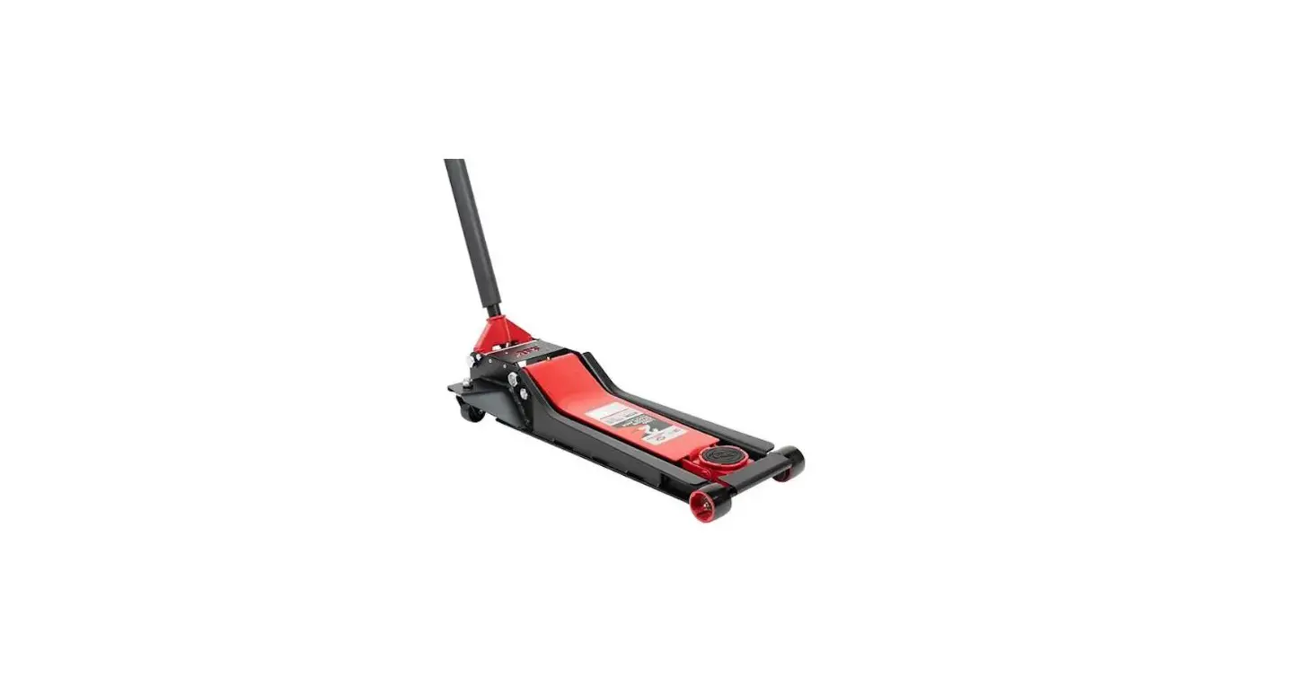
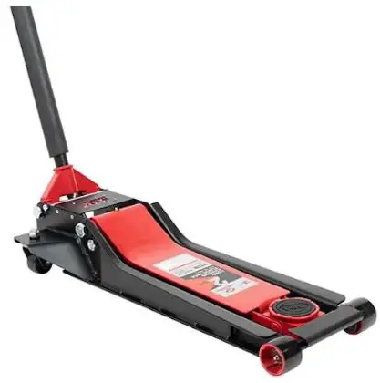
AFF 202LCJ 2 Ton Long Chassis Floor Jack
Product Information
The 2-Ton Long Chassis Floor Jack – Super Duty is a hydraulic floor jack designed to lift, but not support, one end of a vehicle. It is important to note that after lifting, loads must be supported by a pair of appropriately rated jack stands. This floor jack is suitable for use in a working area and should be inspected before each use to ensure it is not damaged, altered, modified, or in poor condition. It should only be used on level and solid ground, with the vehicle’s handbrake engaged, engine switched off, and transmission in gear or PARK (if automatic). A minimum distance of 0.5m should be maintained between the vehicle and static objects to allow for vehicle tilting. Non-essential persons should keep a safe distance while the jack is in use. The rated capacity of the jack should not be exceeded, and the jack should only be placed under lifting points recommended by the vehicle manufacturer. Please note that the warnings, precautions, and instructions provided in this manual may not cover all possible conditions and situations. The operator must exercise common sense and caution while using the product. This product contains chemicals, including nickel, which are known to the State of California to cause cancer and birth defects or other reproductive harm. For more information, visit www.P65Warnings.ca.gov.
Product Usage Instructions
Assembly
Before assembling the floor jack, visually inspect all components for any shipping damage. If any damage is found, notify the carrier immediately as shipping damage is not covered by warranty. Check the parts in the carton and ensure that all components are present.
To assemble the jack:
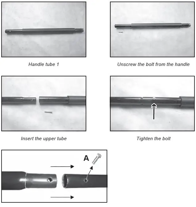
- Unscrew the bolt from handle tube 1.
- Insert the upper handle into the lower handle.
- Secure the two pieces together with the bolt.
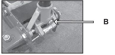
- Undo the screw in the handle socket until it no longer protrudes into the handle socket.
- Insert the pump handle into the handle socket hole completely.
- Ensure that the handle is completely inserted into the socket, then tighten the handle socket screw.
Hydraulic System Purging
The instructions for purging the hydraulic system are not provided in the given text extract. Please refer to the product manual for detailed instructions on purging the hydraulic system.
GENERAL DESCRIPTION
PRODUCT DESCRIPTION
Hydraulic floor jacks are designed to lift, but not support, one end of a vehicle. Immediately after lifting, loads must be supported by a pair of appropriately rated jack stands.
SAFETY INFORMATION
WARNING
- Locate the jack in a suitable working area.
- Inspect the jack before each use. Do not use a jack if damaged, altered, modified, in poor condition, leaking hydraulic fluid, or unstable due to loose or missing hardware or parts. Make corrections before using.
- Use a jack on level and solid ground.
- Ensure the vehicle handbrake is engaged, the engine is switched off, and the transmissions are in gear (or “PARK” if automatic).
- Ensure a minimum distance of 0.5 m between the vehicle and static objects such as doors, walls, etc., to allow for vehicle tilting.
- Ensure all non-essential persons keep a safe distance while the jack is in use.
- Do not exceed the rated capacity of the jack.
- Place the jack under only those lifting points recommended by the vehicle manufacturer (see vehicle handbook).
- Check that the lifting point is stable and centered on the jack saddle.
- Ensure the jack wheels are free to move and that there are no obstructions.
- Use suitable axle stands under the vehicle before proceeding with any task.
- Ensure there are no persons or obstructions beneath the vehicle before lowering.
- Ensure proper routine maintenance is performed by a qualified individual.
- Wear ANSI-approved safety goggles and heavy-duty working gloves during use.
- When not in use store the jack, fully lowered, in a safe, dry, childproof location.
- DO NOT operate the jack if damaged.
- DO NOT allow untrained persons to operate the jack.
- DO NOT exceed the rated capacity of the jack.
- DO NOT move or dolly the vehicle while it is on the jack.
- DO NOT lift the vehicle if there is a risk of spillage of fuel, battery acid, or other dangerous substances.
- DO NOT work under the vehicle until appropriately supported.
- DO NOT fill the hydraulic system with brake fluid, alcohol or transmission oil. Use hydraulic jack oil only.
- DO NOT adjust the safety overload valve.
The warnings, precautions, and instructions discussed in this manual cannot cover all possible conditions and situations that may occur. The operator must understand that common sense and caution are factors, which cannot be built into this product but must be supplied by the operator.
WARNING: This product can expose you to chemicals including nickel, which is known to the State of California to cause cancer and birth defects or other reproductive harm. For more information go to www.P65Warnings.ca.gov.
IMPORTANT RECEIVING INSTRUCTIONS
Visually inspect all components for shipping damage. If any shipping damage is found, notify the carrier at once. Shipping damage is NOT covered by warranty. The carrier is responsible for all repair or replacement costs resulting from damage in shipment.
CHECK THE PARTS IN THE CARTON
Visually inspect all components for any missing parts or damage. Refer to the packing list below.
| No. | Description | Qty |
| 1 | Handle tube 1 | 1 |
| 2 | Handle tube 2 | 1 |
| 3 | Jack body | 1 |
| 4 | Instruction manual | 1 |
ASSEMBLY
- The jack comprises the following parts: Jack body, two-part pumping handle.
- Unscrew the bolt from handle tube 1. Insert the upper handle into the lower handle. Secure the two pieces together with the bolt (A).

- Undo the screw (B) in the handle socket, until it no longer protrudes into the handle socket.
- Insert the pump handle into the handle socket hole completely.
- Ensure that the handle is completely inserted into the socket, then tighten the handle socket screw (B). Please make sure that the handle can be turned smoothly

HYDRAULIC SYSTEM PURGING
- Open the release valve by turning it two full turns counter-clockwise.
- Pump the handle a minimum of four full strokes quickly.
- Close the release valve by turning it clockwise.
- Pumping the handle with full strokes to check if it can reach the maximum height by eight pumps. If it can’t reach the maximum height by eight pumps, please refer to the following special purging process:
- Open the release valve by turning counter-clockwise and lower the lifting arm to the minimum height.
- Put the jack on a flat working table, carefully lift and support the front part of the jack to make sure the front part is at least 500 mm higher than the end part of the jack.
- Pump the handle a minimum of four full strokes quickly.
- Put the jack on a flat surface and close the release valve by turning it clockwise.
- Pumping the handle with full strokes to check if it can reach the maximum height by eight pumps, if not please repeat the special purging process again.
OPERATING INSTRUCTIONS
WARNING
Before use ensure you have read and understood Section 2, Safety Information.
IMPORTANT
Before use, the operator is to visually inspect the jack for cracked welds, damaged or missing parts or hydraulic leak.
RAISING A VEHICLE
- Ensure that the jack and the vehicle are on a hard, level surface.
- Always ensure that the vehicle handbrake is engaged and that the vehicle wheels are chocked.
- Consult the vehicle manual to determine the location of jacking points. Position the jack under a suitable lifting point.
- Turn the handle clockwise, to close release valve. DO NOT over-tighten.
- Raise the vehicle to the desired height by pumping the handle up and down.
- Immediately support the vehicle with appropriate means such as vehicle support stands.
- Turn the release valve slowly counter-clockwise to lower the vehicle on to the vehicle support stands.
LOWERING A VEHICLE
- Ensure that the area under and around the vehicle is clear of people and obstructions.
- Turn the release valve clockwise to close it.
- Pump the handle to raise the vehicle off the vehicle support stands.
- Remove the vehicle support stands from beneath the vehicle.
- Turn the release valve slowly counter-clockwise to lower the vehicle to the ground.
NOTE: When the jack not in use, ALWAYS leave the saddle and ram fully retracted.
CAUTION: Keep hands and feet away from the hinge mechanism of the jack.
IMPORTANT: Only fully qualified personnel should attempt maintenance or repair.
MONTHLY MAINTENANCE
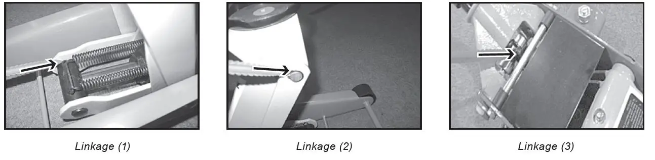
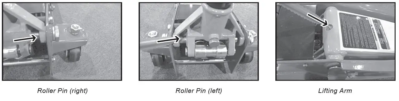
Periodic lubrication is critical to jacks. Any restriction due to dirt or rust can cause either slow jack movement, or extremely rapid jerks, causing damage to the internal components. To keep the jack well lubricated, carry out the following steps.
- Lubricate the linkages the saddle and pump mechanism with light oil.

- Grease the wheel bearing and axles.

- Keep all jack surfaces and warning labels clean.
TRI-MONTHLY MAINTENANCE
- At tri-monthly intervals, check the pump for any signs of rust or corrosion. Clean the pump as required and wipe with an oil cloth.
CHECKING THE OIL LEVEL
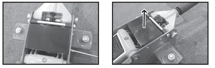
- Fully retract the ram by turning the release valve counter-clockwise.
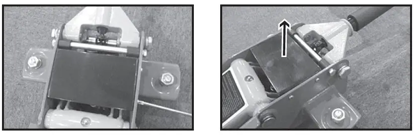
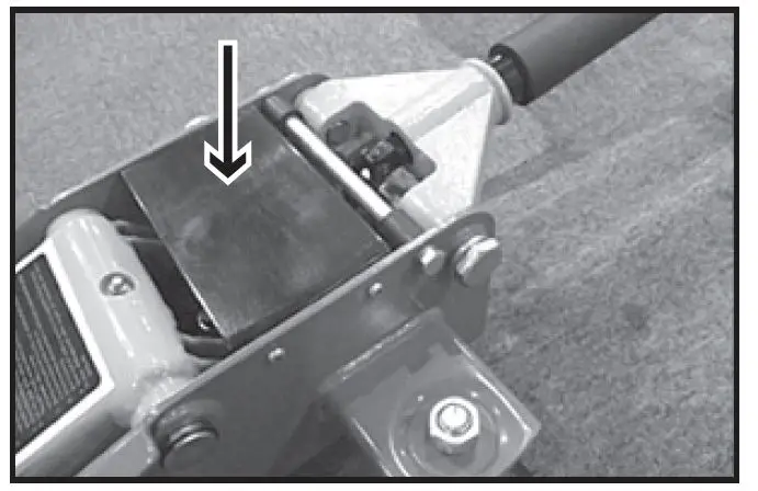
- Loosen and take off the four top plate retaining screws and remove the top plate vertically as pictured below.

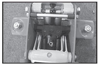
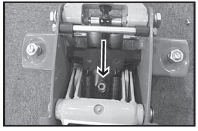
- With the jack in the level position, remove the oil filler plug.
- The proper oil volume should be the maximum distance from the oil surface level to the top of pump and should be less than 11 mm. If there is not enough oil, please add hydraulic oil according to Section 6.4.
- Replace the oil filler plug.
- After adding oil, please checking if the jack can reach the maximum height with eight pumps. If not, please purge air from the hydraulic unit as required. Refer to Section 4.
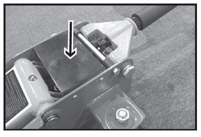
- Cover the top plate, then tighten the four screws.

ADDING OIL
- Fully retract the ram by turning the release valve counter-clockwise.
- Loosen and take off the four top plate retaining screwsand remove the top plate vertically as pictured below.

- With the jack in the level position, remove the oil filler plug.

- Fill with oil through the oil hole and make sure the oil surface level to the top of oil tank is less than 11 mm.

- Replace the oil filler plug, purge air from the hydraulic unit as required. Refer to Section 4.
- Replace the top plate and tighten the four screws.

TROUBLESHOOTING
| PROBLEM | CAUSE | REMEDY |
| Jack will not lift to full height | 1. Oil level low 2. Release valve not closing | 1. Check/add oil 2. Close the release valve |
| Jack will not hold the load | 1. Release valve not closing 2. Hydraulic oil is contaminated 3. Pump leaking | 1. Close the release valve 2. Contact the authorized service agent |
| Lift arm will not lower | 1. Pump cylinder binding 2. Parts worn 3. Internal component damage 4. Return spring broken or unhooked 5. Lift arm linkage either bent or binding 6. Air in the hydraulic system | 1. Contact the authorized service agent |
| After hydraulic purging, the jack still can’t reach the maximum by eight pumps | 1. Still have air in the hydraulic system | 1. Purge air according to manual Part 4.5 |
| Poor lift performance | 1. Fluid level low 2. Hydraulic unit malfunction | 1. Ensure the proper fluid level 2. Discontinue use, contact authorized service agent |
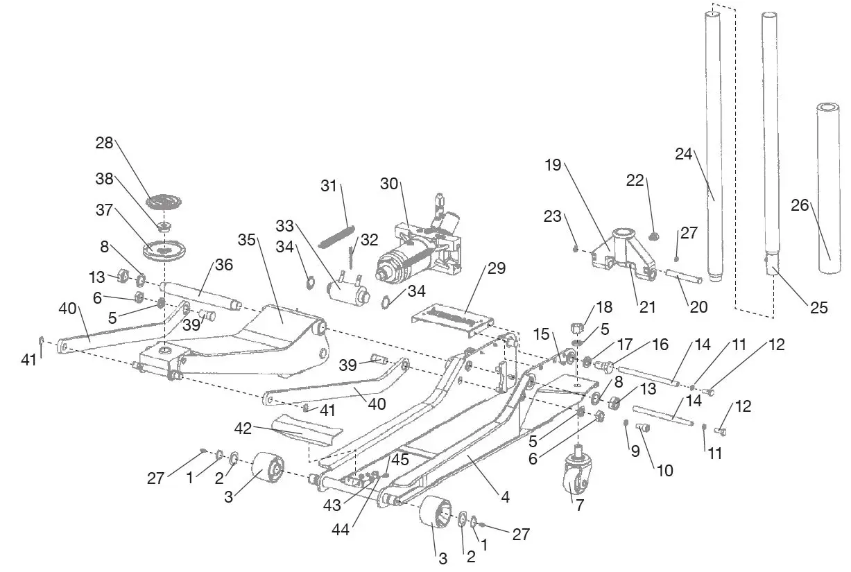
PARTS LIST: 2-TON LONG CHASSIS FLOOR JACK — PARTS BREAKDOWN — Prod. No. 202LCJ
| PART NUMBER | KIT DESCRIPTION | REF. # | KIT INCLUDES |
| 202LCJ-24 | Handle | 24 | Upper Handle |
| 25 | Lower Handle | ||
| 26 | Handle Protection | ||
| 202LCJ-26 | Handle Protection | 26 | Handle Protection |
| 202LCJ-37 | Saddle Complete | 37 | Saddle Complete |
| 38 | Bolt | ||
| 28 | Saddle Pad | ||
| 202LCJ-29 | Cover | 29 | Cover |
| 15 | Screws Qty 4 | ||
| 202LCJ-7 | Caster | 7 | Caster |
| 5 18 | Washer Nut |
| PART NUMBER | KIT DESCRIPTION | REF. # | KIT INCLUDES |
| 202LCJ-27 | Oiler Bowl | 27 | Oiler Bowl |
| 202LCJ-3 | Wheel | 3 | Wheel |
| 2 | Washer | ||
| 1 | Retaining Ring | ||
| 202LCJ-30 | Power Unit | 30 | Power Unit |
| 202LCJ-3 | Spring | 31 | Spring |
| 202LCJ-33 | Block Linkage | 33 | Block Linkage |
| 34 | Retainer Ring | ||
| 202LCJ-22 | Handle Screw | 22 | Handle Screw |
| 202LCJ-50 | Release Valve | 50 | Release Valve |
| 202LCJ-RK | Repair Kit | Repair Kit |
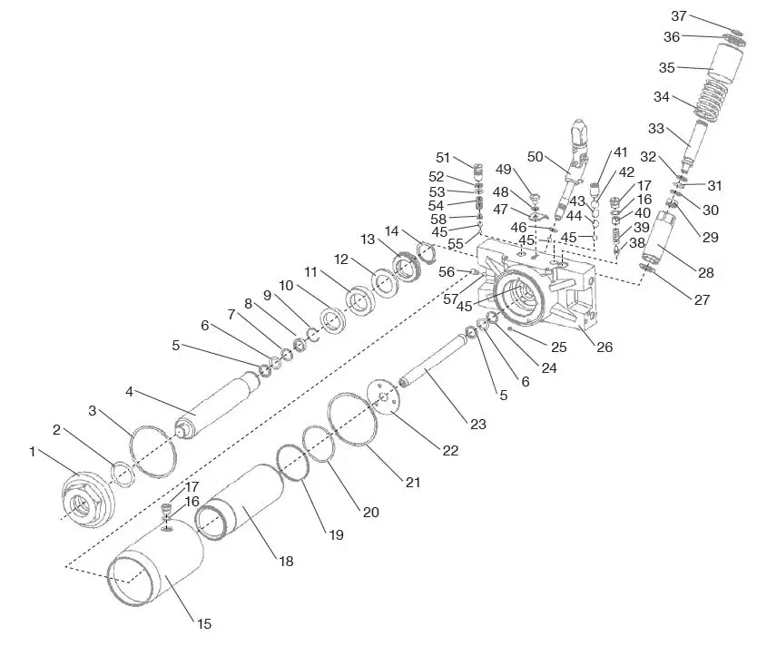
PARTS LIST: 2-TON LONG CHASSIS FLOOR JACK — PARTS BREAKDOWN — Prod. No. 202LCJ
| PART NUMBER | KIT DESCRIPTION | REQ. |
| 1 | Tank Nut | 1 |
| 2 | O-Ring 36 x 3.5 | 1 |
| 3 | Washer | 1 |
| 4 | Ram | 1 |
| 5 | Backup Ring | 2 |
| 6 | O-Ring 12.5 x 2.65 | 2 |
| 7 | Backup Ring | 1 |
| 8 | Guide Ring | 1 |
| 9 | Snap Ring 17 | 1 |
| 10 | Spacer Ring | 1 |
| 11 | Guide Ring | 1 |
| 12 | Washer | 1 |
| 13 | U-Seal | 1 |
| 14 | Retaining Ring 25 | 1 |
| 15 | Cylinder Outer Case | 1 |
| 16 | O-Ring 8.5 x 1.8 | 2 |
| 17 | Screw | 2 |
| 18 | Cylinder Outer Case | 1 |
| 19 | Backup Ring | 1 |
| 20 | O-Ring 46.2 x 2.2 | 1 |
| PART NUMBER | KIT DESCRIPTION | REQ. |
| 21 | Washer | 1 |
| 22 | Washer | 1 |
| 23 | Piston Rod | 1 |
| 24 | Washer | 1 |
| 25 | Permanent Magnet | 1 |
| 26 | Valve Base | 1 |
| 27 | Washer | 1 |
| 28 | Pump Case | 1 |
| 29 | U-Seal | 1 |
| 30 | Backup Ring | 1 |
| 31 | O-Ring 10 x 2.65 | 1 |
| 32 | Backup Ring | 1 |
| 33 | Pump Core | 1 |
| 34 | Pressure Spring | 1 |
| 35 | Pump Outer Case | 1 |
| 36 | Pump Cover | 1 |
| 37 | Snap Ring | 1 |
| 38 | Safety Valve | 1 |
| 39 | Relief Valve Spring | 1 |
| 40 | Screw | 1 |
| PART NUMBER | KIT DESCRIPTION | REQ. |
| 41 | Screw | 1 |
| 42 | Ball 10 | 1 |
| 43 | Separator | 1 |
| 44 | Ball 8 | 1 |
| 45 | Ball 6 | 4 |
| 46 | O-Ring 8 x 1.8 | 1 |
| 47 | Locker | 1 |
| 48 | Spring Washer 6 | 1 |
| 49 | Screw | 1 |
| 50 | Release Assembly | 1 |
| 51 | Screw | 1 |
| 52 | Backup Ring | 1 |
| 53 | O-Ring 6 x 2.65 | 1 |
| 54 | Pressure Spring | 1 |
| 55 | Ball 4 | 1 |
| 56 | Screw M6 x 10 | 1 |
| 57 | Ball 5 | 1 |
| 58 | Ball Saddle | 1 |
LIMITED WARRANTY
SureWerx USA WARRANTS TO ITS CUSTOMERS THAT THE COMPANY’S SureWerx USA “AFF” BRANDED PRODUCTS ARE FREE FROM DEFECTS IN WORKMANSHIP AND MATERIALS. SureWerx USA will repair or replace its SureWerx USA “AFF” branded products that fail to give satisfactory service due to defective workmanship or materials, based upon the terms and conditions of the following described warranty plans attributed to that specific product. This product carries a ONE-YEAR warranty. During this warranty period, SureWerx USA will repair or replace at our option any part or unit which proves to be defective in material or workmanship.
Other important warranty information:
This warranty does not cover damage to equipment or tools arising from alteration, abuse, misuse, or damage and does not cover any repairs or replacement made by anyone other than SureWerx USA. The foregoing obligation is SureWerx USA’s sole liability under this or any implied warranty and under no circumstances shall we be liable for any incidental or consequential damages.
Note: Some states do not allow the exclusion or limitation of incidental or consequential damages, so the above limitation or exclusion may not apply to you. If you have any questions about warranty service, please contact SureWerx USA. This warranty gives you specific legal rights and you may also have other rights which vary from state to state.
contact
- SureWerx, USA Inc.,
- 325 Corporate Drive, Elgin, IL USA 60123
- surewerx.com/usa.
- affjaxx.com.
- 800-323-7402
- surewerx.com.
- affjaxx.com.
WARNING:
IMPORTANT: READ THESE INSTRUCTIONS AND ALL WARNINGS PRIOR TO USING THIS EQUIPMENT. UNDERSTAND ALL OPERATING PROCEDURES, SAFETY WARNINGS AND MAINTENANCE REQUIREMENTS. FAILURE TO DO SO COULD CAUSE AN ACCIDENT RESULTING IN SERIOUS OR FATAL INJURY AND/OR PERSONAL PROPERTY DAMAGE. AFF 202LCJ-INST-3.23.23-FA


