
ZZER ZE-CPE820 Digital Display Wireless Bridge User Manual
INSTRUCTION
- First Set A B A-B mode DIP switch, led L appears and blinks. After the disappearance of L shows an arrangement remain successful.
- The reset button to set the led digital display, click the startup configuration status, then click the automatic increase. Can be continuously increased
- Assume that a pair of bridges with a number of 1 is configured After A set to 1, after the B set to 1, during the LED will flash, L application configuration appears blinking, wait, L foot after flashing into a digital 1, 1 will continue to flash until the A, B are connected After the success, the LED display 1 is always on, not flashing, indicating that the AB has been successfully networked.
| Link | Bridge connection is successful, link lights, not connected Off |
| LAN1 | Turning on the lighting data, the communication flashing, off data nowhere |
| LAN2 | Turning on the lighting data, the communication flashing, off data nowhere |
| PWR | Power indicator, power on |
| LED | Display H, expressed configured to manually set state |
| LED | L displayed and flashes, represents settings |
| LED | Flashing, it indicates to modify the configuration, or is connected to the |
| Round light | A, B status lights, light that is not mode A, mode B light that |
| RST | 1-5s press, led digital automatic increase, 0-F from circulation |
| RST | Press over 10s, release the reset, the system automatically restart |
| LED | A IP | B IP | 2.4 ID | 5.8 ID |
| 0 | 192.168.255.100 | 192.168.255.200 | 0 | 0 |
| 1 | 192.168.255.101 | 192.168.255.201 | 1 | 165 |
| 2 | 192.168.255.102 | 192.168.255.202 | 2 | 161 |
| 3 | 192.168.255.103 | 192.168.255.203 | 3 | 157 |
| 4 | 192.168.255.104 | 192.168.255.204 | 4 | 153 |
| 5 | 192.168.255.106 | 192.168.255.205 | 5 | 149 |
| 6 | 192.168.255.106 | 192.168.255.206 | 6 | 48 |
| 7 | 192.168.255.107 | 192.168.255.207 | 7 | 44 |
| 8 | 192.168.255.108 | 192.168.255.208 | 8 | 40 |
| 9 | 192.168.255.109 | 192.168.255.209 | 9 | 36 |
| a | 192.168.255.110 | 192.168.255.210 | 10 | 140 |
| b | 192.168.255.111 | 192.168.255.211 | 11 | 132 |
| C | 192.168.255.112 | 192.168.255.212 | 13 | 124 |
| D | 192.168.255.113 | 192.168.255.213 | 96 | 116 |
| E | 192.168.255.114 | 192.168.255.214 | 50 | 108 |
| F | 192.168.255.115 | 192.168.255.215 | 55 | 100 |
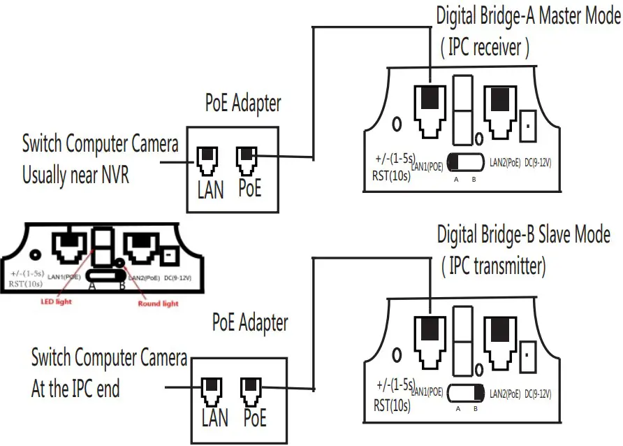
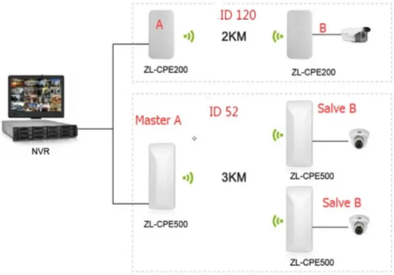
The Building Diagram as follows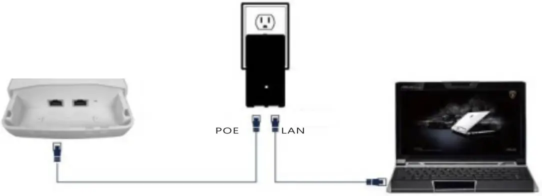
Landing

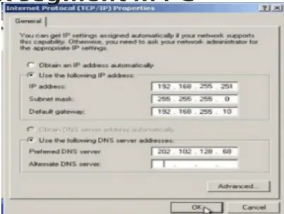
- After power-on, Connect device LAN2 port to the PC network port, Added IP address and subnet mask of 192.168.255.X senment In PC
- Open your bi rowser, and input the ogin IP address of the device (if the device is A enter: http: /1192.168.255.1; if the device is a B Enter http://192.168.255.2) and press Enter for login WEB Management Interface. In order to ensure the best display for WEB , Make sure to use the latest version
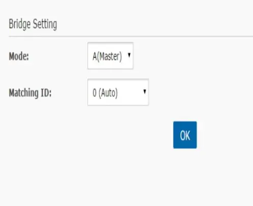
A device configuration

- Enter the interface of (Bridge Set]
- Bridge mode is set to mode A
- Set the ID number (The ID number of device A is same with pairing device Et)
- After Press the (Application settings) Buttom the configuration is effective
B device configuration

- Enter the interface of (Bridge Set]
- BrIdge mode Is set to mode B
- Set the ID number (The ID number of device B is same with pairing device A)
- After Press the (Application settings) Buttom the configuration is effective
Note:
- For One-to-many Setting. The ID number must be same for A device and mroe devices B
- For more “One-to-many Setting” Keep the ID number are different, for this can Avoid ring to each other.
- In the login window to enter a user name and password (the default are both: admin), and press the “OK” button.
- After successful login into the bridge configuration interface

Using schematic
- One to One is used for connection between two devices. 2.0net to More is used for connection between One device A and more devices B

FCC Warning Statement
Changes or modifications not expressly approved by the party responsible for compliance could void the user’s authority to operate the equipment. This equipment has been tested and found to comply with the limits for a Class B digital device, pursuant to Part 15 of the FCC Rules. These limits are designed to provide reasonable protection against harmful interference in a residential installation. This equipment generates uses and can radiate radio frequency energy and, if not installed and used in accordance with the instructions, may cause harmful interference to radio communications. However, there is no guarantee that interference will not occur in a particular installation. If this equipment does cause harmful interference to radio or television reception, which can be determined by turning the equipment off and on, the user is encouraged to try to correct the interference by one or more of the following measures:
- Reorient or relocate the receiving antenna.
- Increase the separation between the equipment and receiver.
- Connect the equipment into an outlet on a circuit different from that to which the receiver is connected.
- Consult the dealer or an experienced radio/TV technician for help.
This device complies with part 15 of the FCC Rules. Operation is subject to the following two conditions:
- This device may not cause harmful interference, and
- this device must accept any interference received, including interference that may cause undesired operation.
RF Exposure Statement
To maintain compliance with FCC’s RF Exposure guidelines, This equipment should be installed and operated with minimum distance of 20cm the radiator your body. This device and its antenna(s) must not be co-located or operation in conjunction with any other antenna or transmitter


