
Qubino
Flush 1D relay
SKU: GOAEZMNHAD1

Quickstart
This is a
On/Off Power Switch
for
Europe.
To run this device please connect it to your mains power supply.
Auto-inclusion procedure, first set main controller into inclusion mode and then connect module to power supply.”
NOTE: When connecting temperature sensor to module that has already been included, you have to exclude module first. Switch off power supply , connect the sensor and re-include the module.
Important safety information
Please read this manual carefully. Failure to follow the recommendations in this manual may be dangerous or may violate the law.
The manufacturer, importer, distributor and seller shall not be liable for any loss or damage resulting from failure to comply with the instructions in this manual or any other material.
Use this equipment only for its intended purpose. Follow the disposal instructions.
Do not dispose of electronic equipment or batteries in a fire or near open heat sources.
What is Z-Wave?
Z-Wave is the international wireless protocol for communication in the Smart Home. This
device is suited for use in the region mentioned in the Quickstart section.

Z-Wave ensures a reliable communication by reconfirming every message (two-way
communication) and every mains powered node can act as a repeater for other nodes
(meshed network) in case the receiver is not in direct wireless range of the
transmitter.
This device and every other certified Z-Wave device can be used together with any other
certified Z-Wave device regardless of brand and origin as long as both are suited for the
same frequency range.
If a device supports secure communication it will communicate with other devices
secure as long as this device provides the same or a higher level of security.
Otherwise it will automatically turn into a lower level of security to maintain
backward compatibility.
For more information about Z-Wave technology, devices, white papers etc. please refer
to www.z-wave.info.
Product Description
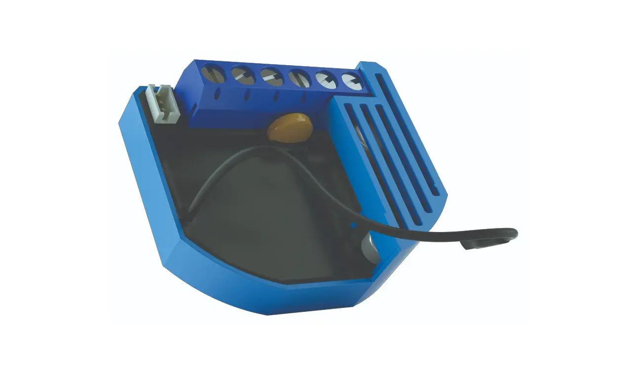
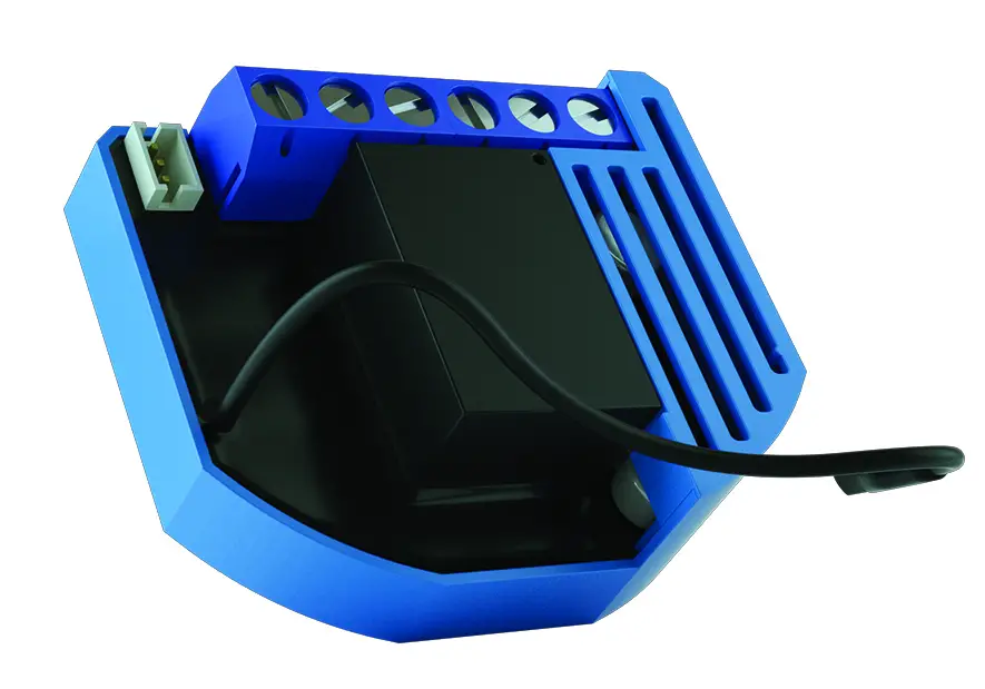
Qubino Flush 1D relay with voltage free (dry contact) output contact.
This Z-Wave module is used for switching on or off the electrical device (e.g. light, fan, etc …). The module can be controlled either through Z-wave network or through the wall switch.
The module is designed to be mounted inside a âflush mounting boxâ, hidden behind a traditional wall switch.
Module supports connection of digital temperature sensor. It is designed to act as repeater in order to improve range and stability of Z-wave network.
Output contact is voltage free (dry contact), so also loads with different power supply can be connected to the module.
Prepare for Installation / Reset
Please read the user manual before installing the product.
In order to include (add) a Z-Wave device to a network it must be in factory default
state. Please make sure to reset the device into factory default. You can do this by
performing an Exclusion operation as described below in the manual. Every Z-Wave
controller is able to perform this operation however it is recommended to use the primary
controller of the previous network to make sure the very device is excluded properly
from this network.
Reset to factory default
This device also allows to be reset without any involvement of a Z-Wave controller. This
procedure should only be used when the primary controller is inoperable.
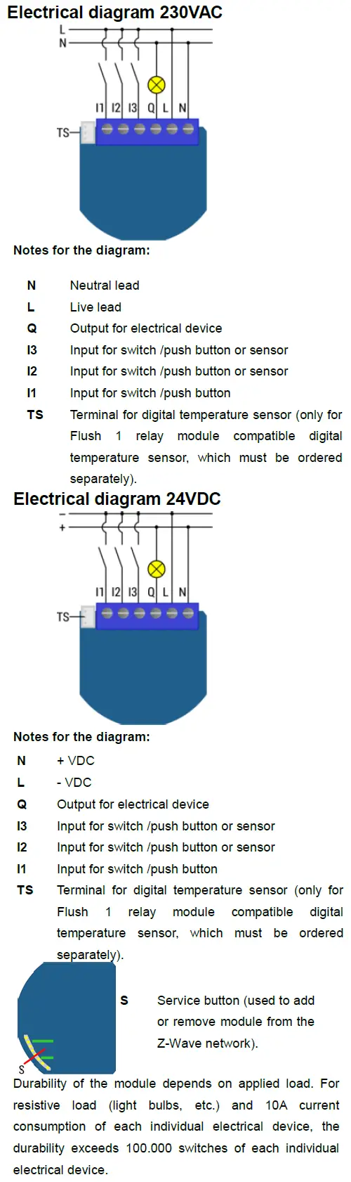
If the service button S is pressed for mor ethan 6 seconds the module will be reset to the factory defoult state
Safety Warning for Mains Powered Devices
ATTENTION: only authorized technicians under consideration of the country-specific
installation guidelines/norms may do works with mains power. Prior to the assembly of
the product, the voltage network has to be switched off and ensured against re-switching.
Installation
⢠Do not shorten the antenna.
Inclusion/Exclusion
On factory default the device does not belong to any Z-Wave network. The device needs
to be added to an existing wireless network to communicate with the devices of this network.
This process is called Inclusion.
Devices can also be removed from a network. This process is called Exclusion.
Both processes are initiated by the primary controller of the Z-Wave network. This
controller is turned into exclusion respective inclusion mode. Inclusion and Exclusion is
then performed doing a special manual action right on the device.
Inclusion
⢠Press service button S for more than 2 second or press push button I1 three times within 3s (3 times change switch state within 3 seconds).
Exclusion
⢠Press service button S for more than 6 second or press push button I1 five times within 3s ( 5 times change switch state within 3 seconds) in the first 60 seconds after the module is connected to the power supply.”
Note:” By this function all parameters of the module are set to default values and own ID is deleted. If service button S is pressed more than 2 and less than 6second module is excluded, but configuration parameters are not set to default values
Auto-Inclusion
Beside the standard inclusion this devices supports the so called auto inclusion.
Right after powering up the device remains in inclusion state and can be included by
(any) gateway without further actions on the device itself. The auto inclusion mode will
time out after some time.
Product Usage
Quick trouble shooting
Here are a few hints for network installation if things dont work as expected.
- Make sure a device is in factory reset state before including. In doubt exclude before include.
- If inclusion still fails, check if both devices use the same frequency.
- Remove all dead devices from associations. Otherwise you will see severe delays.
- Never use sleeping battery devices without a central controller.
- Dont poll FLIRS devices.
- Make sure to have enough mains powered device to benefit from the meshing
Association – one device controls an other device
Z-Wave devices control other Z-Wave devices. The relationship between one device
controlling another device is called association. In order to control a different
device, the controlling device needs to maintain a list of devices that will receive
controlling commands. These lists are called association groups and they are always
related to certain events (e.g. button pressed, sensor triggers, …). In case
the event happens all devices stored in the respective association group will
receive the same wireless command wireless command, typically a ‘Basic Set’ Command.
Association Groups:
Group NumberMaximum NodesDescription
| 1 | 1 | Lifeline group (reserved for communication with the main controller). |
| 2 | 16 | basic on/off (triggered at change of the output state and reflecting its state) nodes. |
| 3 | 16 | basic on/off (triggered at change of the input I2 state and reflecting its state). |
| 4 | 16 | Binary Sensor Report (triggered at change of the input I2 state and reflecting its state). |
| 5 | 16 | Notification Report (triggered at change of the input I2 state and reflecting its state). |
Configuration Parameters
Z-Wave products are supposed to work out of the box after inclusion, however
certain configuration can adapt the function better to user needs or unlock further
enhanced features.
IMPORTANT: Controllers may only allow configuring
signed values. In order to set values in the range 128 … 255 the value sent in
the application shall be the desired value minus 256. For example: To set a
parameter to 200âit may be needed to set a value of 200 minus 256 = minus 56.
In case of a two byte value the same logic applies: Values greater than 32768 may
needed to be given as negative values too.
Parameter 1: Input 1 switch type
Defines the type of switch connected to Input 1
Size: 1 Byte, Default Value: 1
SettingDescription
| 0 | mono-stable switch type (push button) |
| 1 | bi-stable switch type |
Parameter 2: Input 2 contact type
Defines the type of switch connected to Input 2
Size: 1 Byte, Default Value: 0
SettingDescription
| 0 | NO (normally open) input type |
| 1 | NC (normally close) input type |
Parameter 3: Input 3 contact type
Defines the type of switch connected to Input 3
Size: 1 Byte, Default Value: 0
SettingDescription
| 0 | NO (normally open) input type |
| 1 | NC (normally close) input type |
Parameter 10: Activate / deactivate functions ALL ON/ALL OFF
Support to activate / deactivate functions ALL ON/ALL OFFFlush 1D relay module responds to commands ALL ON / ALL OFF that may be sent by the main controller or by other controller belonging to the system.
Size: 2 Byte, Default Value: 255
SettingDescription
| 255 | ALL ON active, ALL OFF active |
| 0 | ALL ON is not active ALL OFF is not active |
| 1 | ALL ON is not active ALL OFF active |
| 2 | ALL ON active ALL OFF is not active |
Parameter 11: Automatic turning off output after set time
Support automatic turning off output after set time.When relay is ON it goes automatically OFF after time defined by this parameter. Timer is reset to zero each time the module receive ON command regardless from where it comes (push button, associated module, controller,..).
Size: 2 Byte, Default Value: 0
SettingDescription
| 0 | Auto OFF disabled |
| 1 – 32535 | 1 – 32535 = 1second (0,01s) – 32535 seconds (325,35s) Auto OFF enabled with define time, step is 1s or 10ms according to parameter nr.15 |
Parameter 12: Automatic turning on output after set time
Support automatic turning on output after set time When relay is OFF it goes automatically ON after time defined by this parameter. Timer is reset to zero each time the module receive OFF command regardless from where it comes (push button, associated module, controller,..).
Size: 2 Byte, Default Value: 0
SettingDescription
| 0 | Auto ON disabled |
| 1 – 32535 | 1 – 32535 = 1second (0,01s) – 32536 seconds (325,35s) Auto ON enabled with define time, step is 1s or 10ms according to parameter nr.15 |
Parameter 15: Automatic turning off / on seconds or milliseconds selection
Support automatic turning off / on seconds or milliseconds selectionNOTE: This parameter is valid for both, turning on and turning off parameters.
Size: 1 Byte, Default Value: 0
SettingDescription
| 0 | seconds selected |
| 1 | milliseconds selected |
Parameter 30: Saving the state of the relay after a power failure
Support saving the state of the relay after a power failure
Size: 1 Byte, Default Value: 0
SettingDescription
| 0 | Flush 1D relay module saves its state before power failure (it returns to the last position saved before a power failure) |
| 1 | Flush 1D relay module does not save the state after a power failure, it returns to "off" position. |
Parameter 40: Power reporting in Watts on power change for Q1
Set value means percentage, set value from 0 – 100 = 0% – 100%.
Size: 1 Byte, Default Value: 10
SettingDescription
| 0 | Reporting Disabled |
| 1 – 100 | 1% – 100% Reporting enabled. Power report is send (push) only when actual power in Watts in real time changes for more than set percentage comparing to previous actual power in Watts, step is 1%. NOTE: if power changed is less than 1W, the report is not send (pushed), independent of percentage set. |
Parameter 42: Power reporting in Watts by time interval for Q1
Set value means time interval (0 – 32535) in seconds, when power report is send.
Size: 2 Byte, Default Value: 300
SettingDescription
| 0 | Reporting Disabled |
| 1 – 32535 | = 1 second – 32535 seconds. Reporting enabled, Power report is send with time interval set by entered value. |
Parameter 63: Output Switch selection
Support output Switch selectionSet value means the type of the device that is connected to the output. The device type can be normally open (NO) or normally close (NC).
Size: 1 Byte, Default Value: 0
SettingDescription
| 0 | When system is turned off the output is 0V (NC). |
| 1 | When system is turned off the output is 230V or 24V (NO). |
Parameter 100: Enable / Disable Endpoint I2 or select Notification Type and Event
Support Enable / Disable Endpoint I2 or select Notification Type and EventEnabling I2, means that Endpoint (I2) will be present on UI. Disabling it will result in hiding the endpoint according to the parameter set value. Additionally, a Notification Type and Event can be selected for the endpoint. NOTE: After parameter change module has to be reincluded into the network for the setting to take effect!
Size: 1 Byte, Default Value: 1
SettingDescription
| 1 | Home Security; Motion Detection, unknown location |
| 2 | Carbon Monoxide; Carbon Monoxide detected, unknown location. |
| 3 | Carbon Dioxide; Carbon Dioxide detected, unknown location. |
| 4 | Water Alarm; Water Leak detected, unknown location. |
| 5 | Heat Alarm; Overheat detected, unknown location. |
| 6 | Smoke Alarm; Smoke detected, unknown location. |
| 0 | Endpoint, I2 disabled |
Parameter 101: Enable / Disable Endpoint I3 or select Notification Type and Event
Support Enable / Disable Endpoint I3 or select Notification Type and EventEnabling I3, means that Endpoint (I3) will be present on UI. Disabling it will result in hiding the endpoint according to the parameter set value. Additionally, a Notification Type and Event can be selected for the endpoint. NOTE: After parameter change module has to be reincluded into the network for the setting to take effect!
Size: 1 Byte, Default Value: 1
SettingDescription
| 1 | Home Security; Motion Detection, unknown location |
| 2 | Carbon Monoxide; Carbon Monoxide detected, unknown location. |
| 3 | Carbon Dioxide; Carbon Dioxide detected, unknown location. |
| 4 | Water Alarm; Water Leak detected, unknown location. |
| 5 | Heat Alarm; Overheat detected, unknown location. |
| 6 | Smoke Alarm; Smoke detected, unknown location. |
| 0 | Endpoint, I3 disabled |
Parameter 110: Temperature sensor offset settings
Defines temperature sensor offset settingsSet value is added or subtracted to actual measured value by sensor.
Size: 2 Byte, Default Value: 32536
SettingDescription
| 32536 | offset is 0.0C |
| 1 – 100 | value from 0.1C to 10.0C is added to actual measured temperature. |
| 1001 – 1100 | value from -0.1C to -10.0C is subtracted to actual measured temperature. |
Parameter 120: Digital temperature sensor reporting
Defines the digital temperature sensor reportingIf digital temperature sensor is connected, module reports measured temperature on temperature change defined by this parameter.
Size: 1 Byte, Default Value: 5
SettingDescription
| 0 | Reporting disabled |
| 1 – 127 | 0,1C – 12,7C, step is 0,1C |
Technical Data
| Dimensions | 0.0150000×0.0370000×0.0420000 mm |
| Weight | 28 gr |
| Hardware Platform | ZM5202 |
| EAN | 3830062070102 |
| IP Class | IP 20 |
| Voltage | 230 V |
| Load | 2300 W |
| Device Type | On/Off Power Switch |
| Network Operation | Always On Slave |
| Z-Wave Version | 6.51.06 |
| Certification ID | ZC10-15070017 |
| Z-Wave Product Id | 0x0159.0x0002.0x0053 |
| Frequency | Europe – 868,4 Mhz |
| Maximum transmission power | 5 mW |
Supported Command Classes
- Switch All
- Association
- Association Group Information
- Basic
- Sensor Binary
- Configuration
- Device Reset Locally
- Manufacturer Specific
- Multi Channel
- Multi Channel Association
- Sensor Multilevel
- Notification
- Powerlevel
- Switch Binary
- Version
- Zwaveplus Info
Controlled Command Classes
- Basic
Explanation of Z-Wave specific terms
- Controller — is a Z-Wave device with capabilities to manage the network.
Controllers are typically Gateways,Remote Controls or battery operated wall controllers. - Slave — is a Z-Wave device without capabilities to manage the network.
Slaves can be sensors, actuators and even remote controls. - Primary Controller — is the central organizer of the network. It must be
a controller. There can be only one primary controller in a Z-Wave network. - Inclusion — is the process of adding new Z-Wave devices into a network.
- Exclusion — is the process of removing Z-Wave devices from the network.
- Association — is a control relationship between a controlling device and
a controlled device. - Wakeup Notification — is a special wireless message issued by a Z-Wave
device to announces that is able to communicate. - Node Information Frame — is a special wireless message issued by a
Z-Wave device to announce its capabilities and functions.


