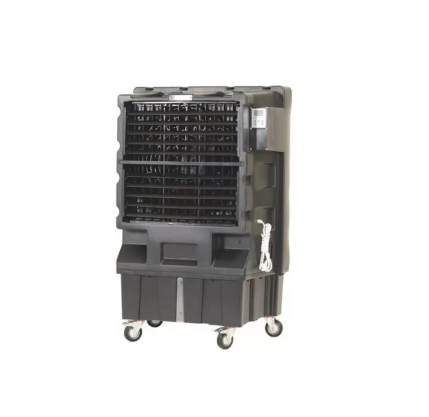
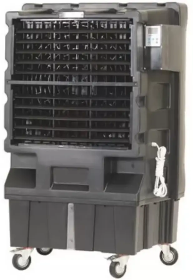
SOVELOR COLD120 Mobile Air Freshener
INFORMATION ON
SAFETY
| IMPORTANT: READ AND UNDERSTAND THIS OPERATIONAL MANUAL BEFORE ASSEMBLING, COMMISSIONING OR PERFORMING MAINTENANCE ON THIS APPLIANCE. INCORRECT USE OF THE APPLIANCE CAN CAUSE SERIOUS INJURY. KEEP THIS MANUAL FOR FURTHER REFERENCE. |
| IMPORTANT: This appliance is not suitable for use by persons (including children) with reduced physical, sensory and mental capacities or with lack of experience or knowledge unless supervised by a person responsible for their safety. Children must be supervised to make sure they do not play with the appliance |
- Fill the appliance tank only with clean water.
- Switch off and disconnect the appliance from the mains before filling it.
- Do not move the appliance, once the tank has been filled.
- Comply with all local regulations and current standard during appliance use.
- Keep the appliance dry, in order to avoid electric shocks. Hands must always be dry.
- Use only in ventilated and dry areas.
- For indoor use only.
- Only power the appliance the with voltage and frequency as specified on the nameplate.
- Only use suitably earthed 3-wire extension leads.
- Do not cover the appliance with paper, cardboard, plastic, metal sheets or any other inflammable material during use, in order to prevent any risk.
- The appliance must be used on a stable and levelled surface, in order to prevent any risk.
- Disconnect the appliance from the mains socket when not in use.
- Do not block the air vent (rear side) or the air outlet (front side) of the appliance. The minimum safety distance recommended between the appliance and walls or other items is 0,5 m.
- When the appliance is connected to the mains or running, it must never be moved, handled, topped-up or subject to any maintenance operation.
- The appliance (power cable included) must be kept at a suitable safety distance from heat sources.
- In any case, the appliance must be opened and/or repaired by authorised after-sales centre.
- If the power supply cable is damaged, it must be replaced by a technical support centre to prevent any risk.
- After a period of inactivity, wash the tank with clean water.
- In the event of incorrect cooler operation, immediately disconnect the electrical power supply and contact the support centre.
- Protect the power cable from potential damage caused by the movement of vehicles or pedestrians. Improper connection to electrical voltage or improper installation may result in electric shocks.
- Conditions of use:
A) Temperature of the air: 18°C – 45°C; Temperature of the water: <45°C.
B) The air must be free of dust and pollutants, otherwise cleaning must be intensified.
UNPACKING
- Remove all packaging materials used to wrap and deliver the appliance and dispose of them in compliance with the Standards in force.
- Extract all items from the packaging.
- Verify if damage has occurred during transport. Immediately inform the dealer where the appliance was purchased if this appears damaged.
ASSEMBLY
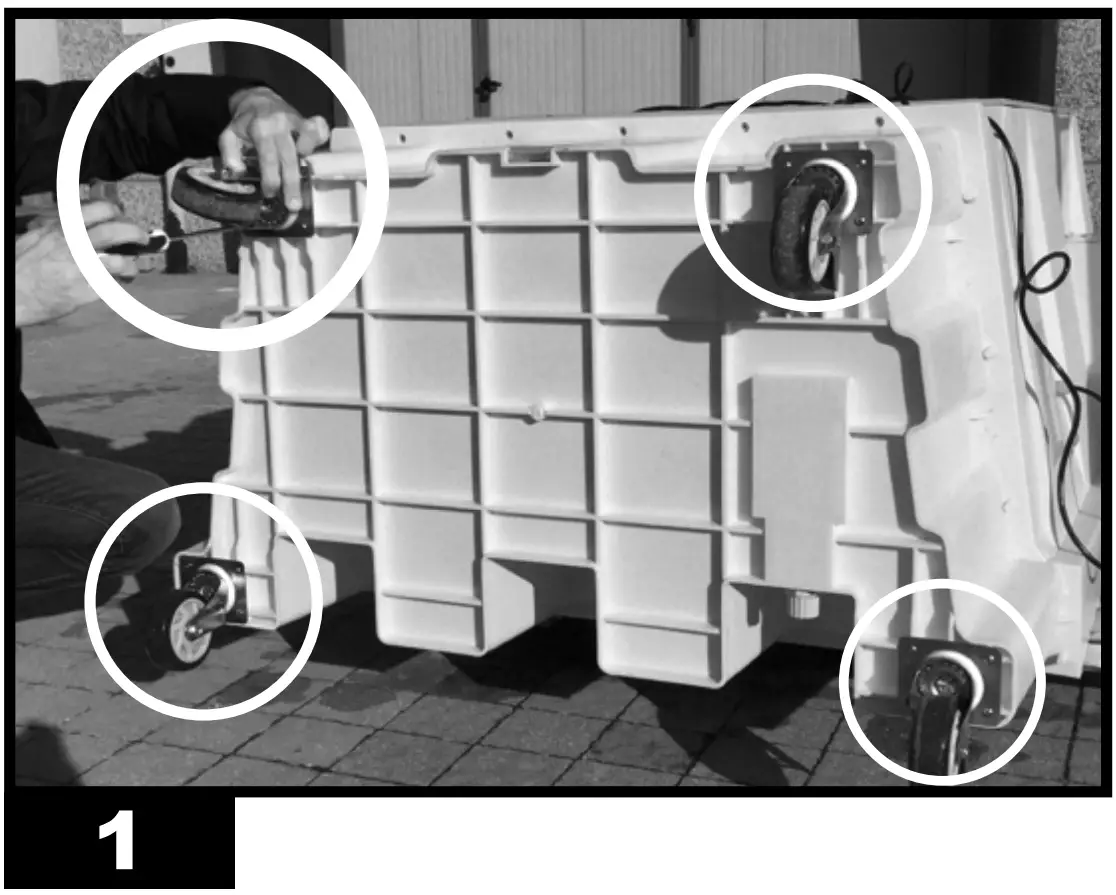
The device is equipped with wheels to facilitate handling. Depending on the model, wheels can be found already installed or not. Components equipped with relative nuts and bolts are found inside the packaging (Fig. 1)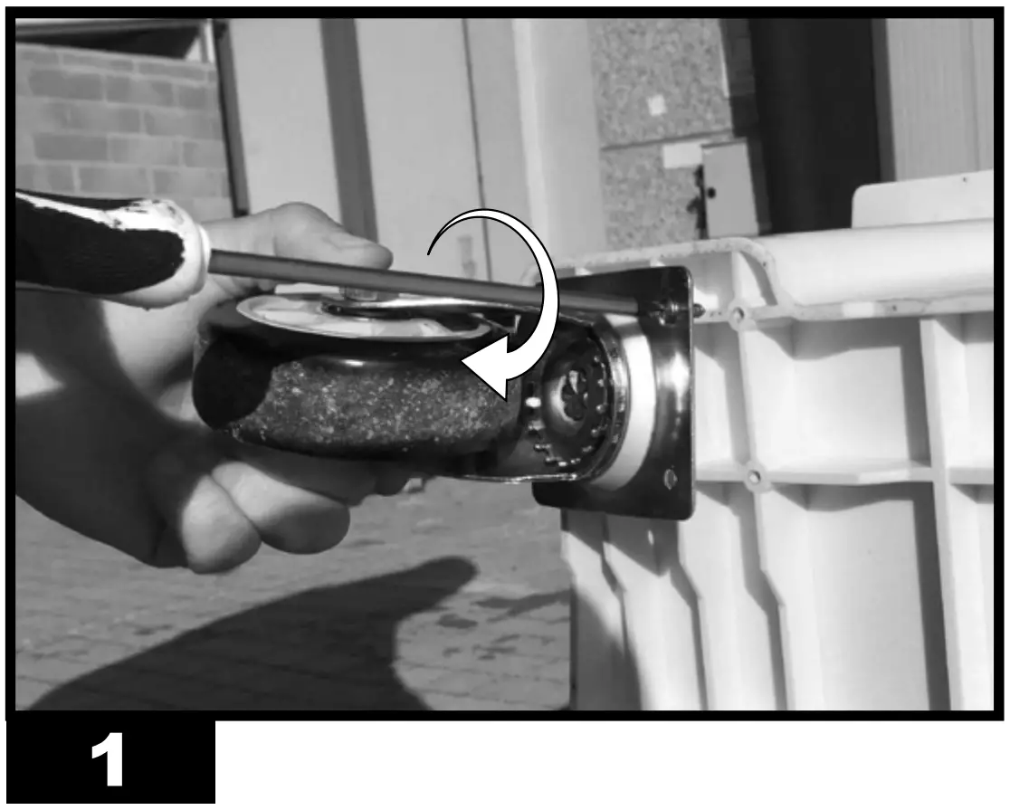
OPERATION
| WARNING: Thoroughly read the ”INFORMATION REGARDING SAFETY”, before switching the appliance on. |
| WARNING: Only use clean water to prevent failures or other anomalies. |
| WARNING: Verify if your electronic system is earthed correctly. Connection to the mains must be made in compliance with the National Standards in force. Only power the appliance the with voltage and frequency as specified on the nameplate. |
NOTE: These models can be connected to the water mains, by connecting the pipe to the fitting (Fig. 10).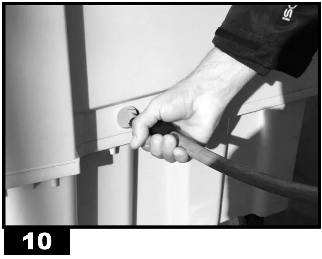 |
SWITCH-ON:
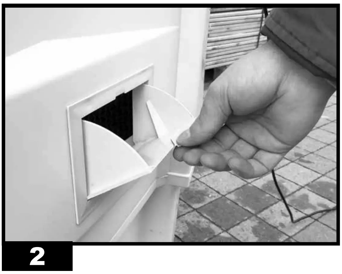
- Open the tank door (Fig. 2).

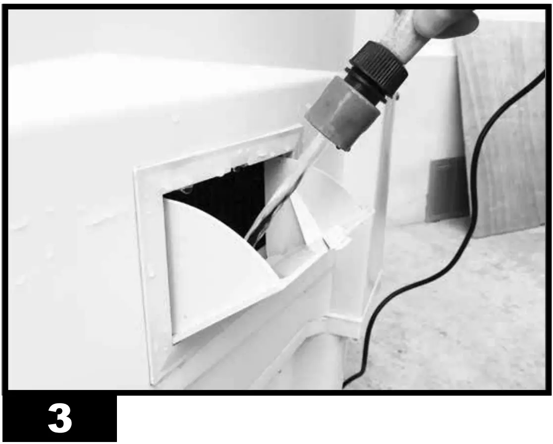
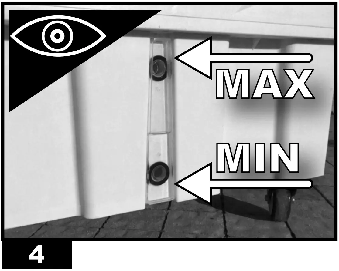
- Fill the tank with water (Fig. 3), the water level must be between MIN and MAX of the graduated scale (Fig. 4), so as to avoid risks.
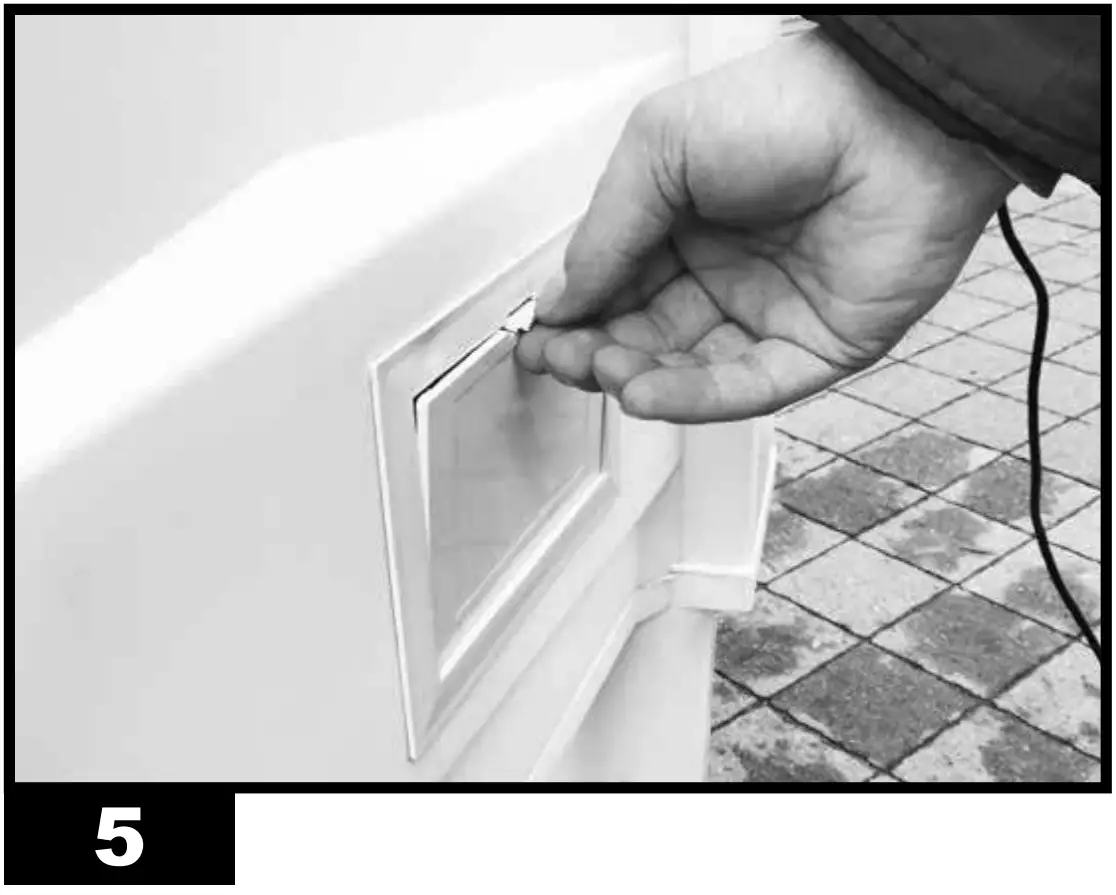
- Close the tank door (Fig. 5).
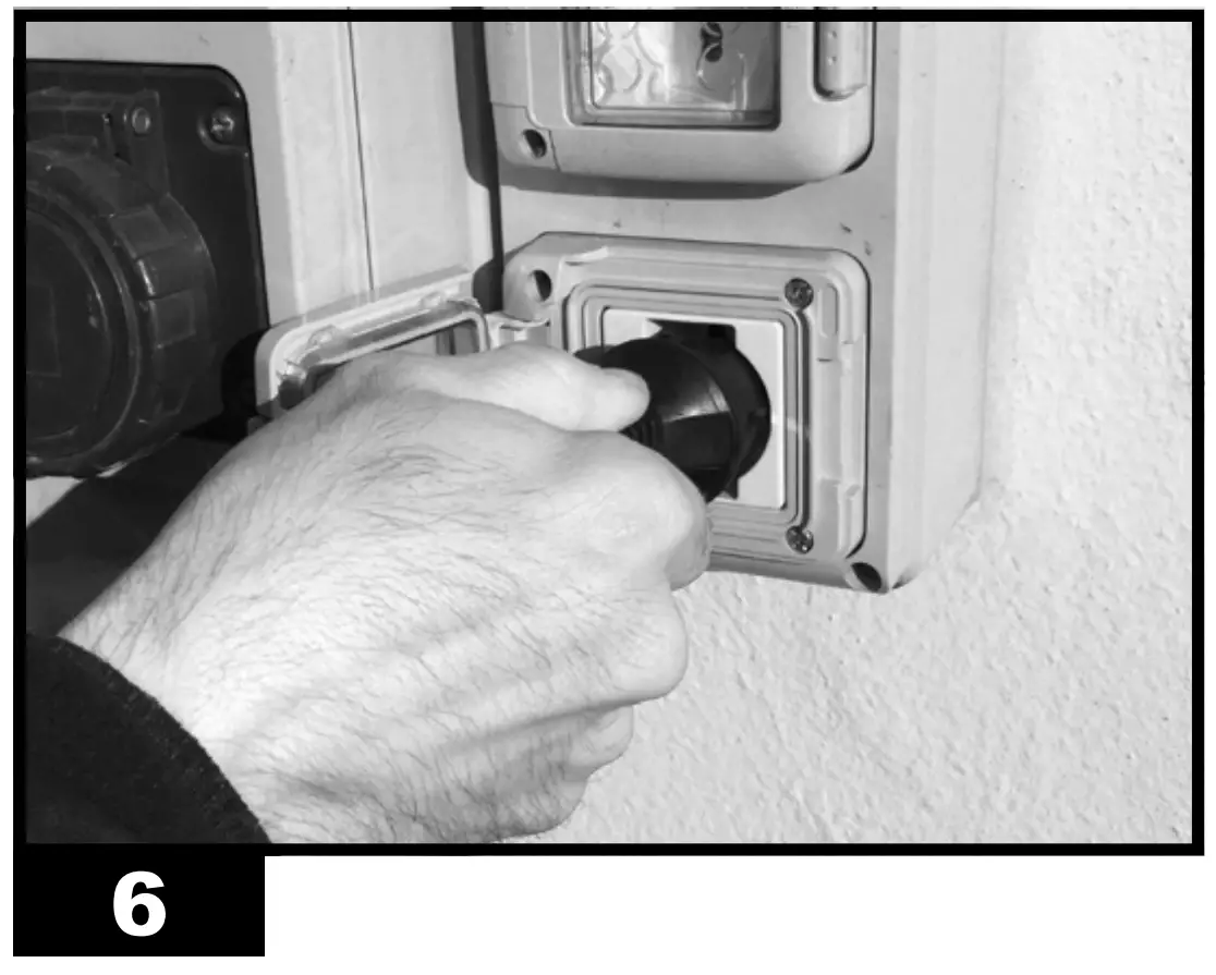
- Connect the power plug to the mains (Fig. 6).
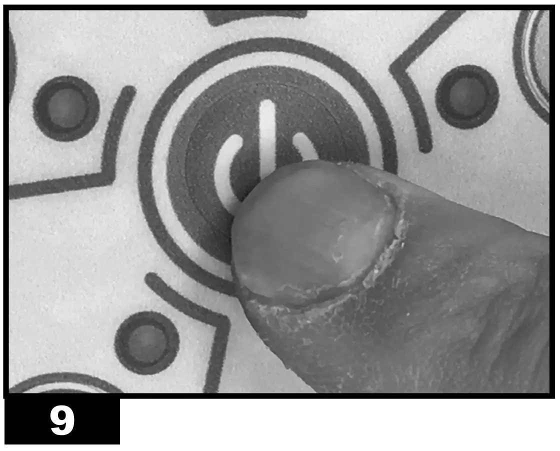
- Press the “ON/OFF”/“POWER” button to switch on the appliance (Fig. 9).

CONTROL PANEL AND FUNCTIONS (Fig. 7):
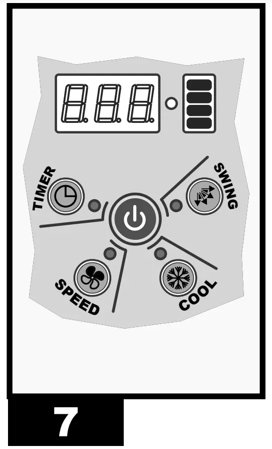
- ON/OFF: Turns on or off the device.
- SPEED: Increases or decreases the ventilation speed of the device. You can choose from three speeds.
- COOL: Enables or disables the cooling mode.
- SWING: Enables or disables the automatic swing of the fins to direct the air flow.
- TIMER: Enables to activate or deactivate the delayed switch-on or switch-off
mode.
– Delayed switch-on: When the cooler is on, press the “TIMER” button repeatedly until the desired time is displayed (the number flashes), then switch off the equipment.
– Delayed switch-off: When the cooler is on, press the “TIMER” button repeatedly until the desired time is displayed, then the switch-off time is set.
| NOTE: When the cooler emits an acoustic beep, it means that the tank is empty and must be filled again (“COOL” function). To deactivate the acoustic beep, deactivate the “COOL” function. |
REMOTE CONTROL AND FUNCTIONS (Fig. 8):
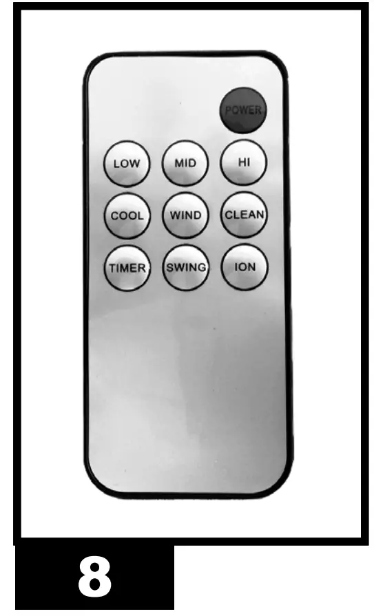
- POWER: Turns on or off the device.
- LOW – MID – HIGH: Increases or decreases the ventilation speed of the device. You can choose from three speeds: LOW, MID and HIGH.
- COOL: Enables the cooling mode.
- WIND: Enables the ventilation mode ONLY.
- SWING: Enables or disables the automatic swing of the fins to direct the air flow.
- TIMER: Enables to activate or deactivate the delayed switch-on or switch-off mode.
– Delayed switch-on: When the cooler is on, press the “TIMER” button repeatedly until the desired time is displayed (the number flashes), then switch off the equipment.
– Delayed switch-off: When the cooler is on, press the “TIMER” button repeatedly until the desired time is displayed, then the switch-off time is set.
SWITCH-OFF
- Press the “ON/OFF”/“POWER” button to switch off the appliance (Fig. 9).
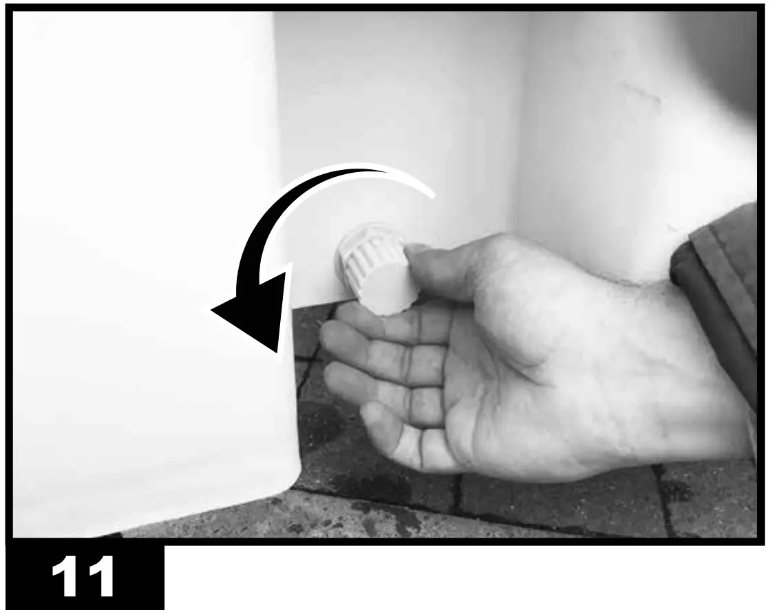
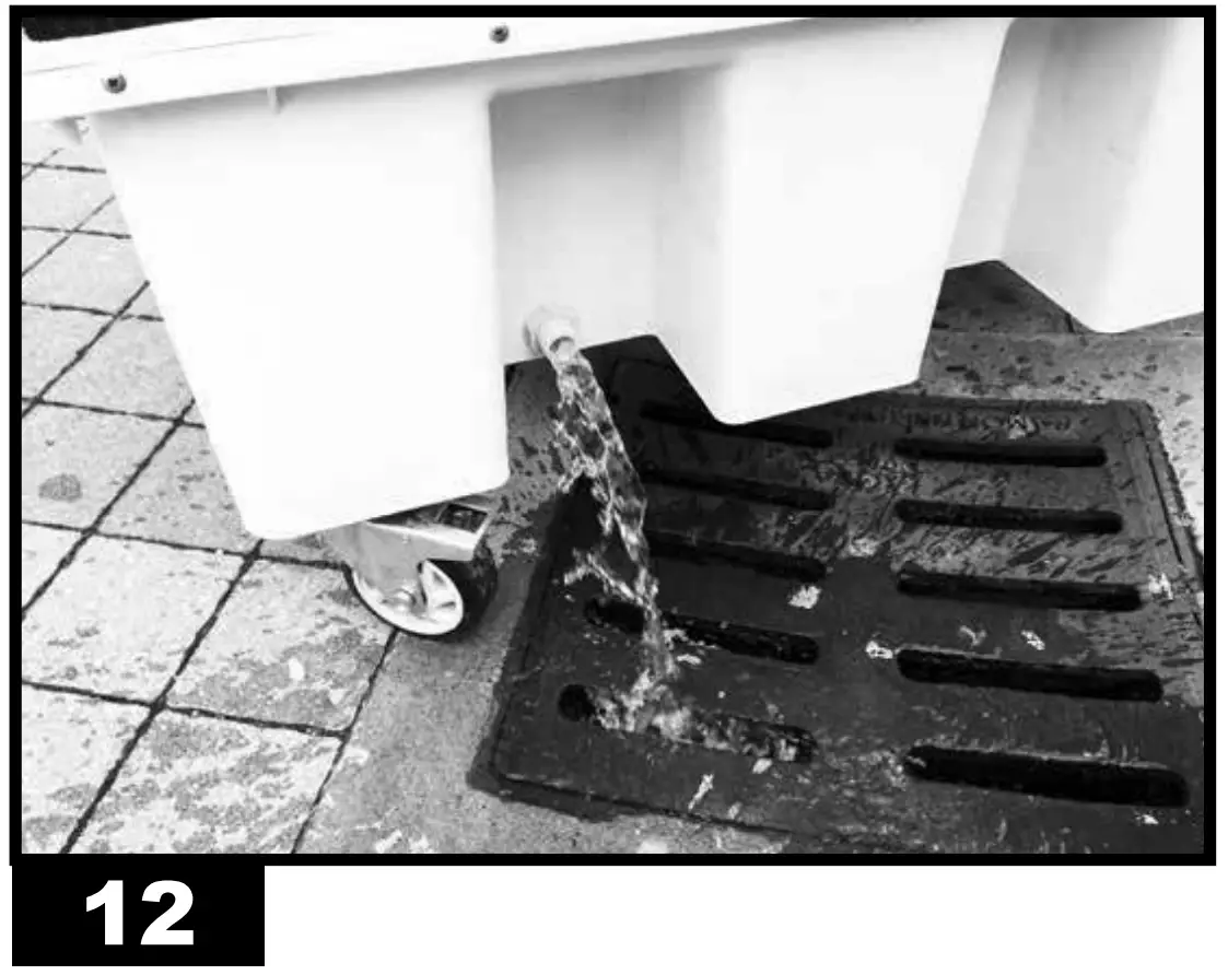
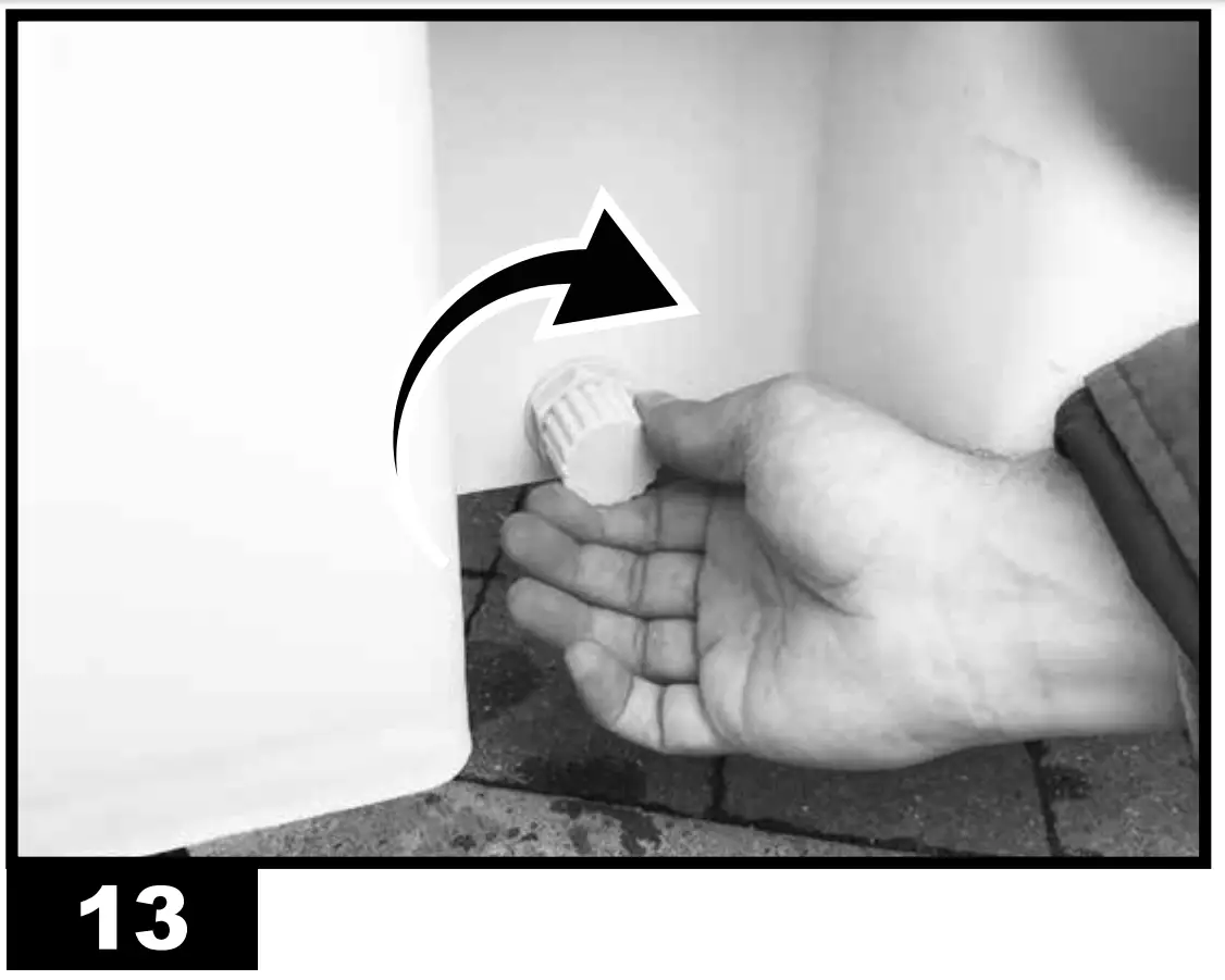
- Drain the tank through the specific drain plug (Fig. 11-12-13).


CLEANING AND MAINTENANCE
| WARNING: BEFORE PERFORMING ANY MAINTENANCE OR REPAIR, DISCONNECT THE POWER CABLE FROM THE MAINS. |
DEPENDING ON THE ENVIRONMENT WHERE THE APPLIANCE IS USED, DUST, DIRT OR WATER QUALITY CANAFFECT THE PERFORMANCE OF THE UNIT. THEREFORE, CLEANING THE FOLLOWING COMPONENTS MAY BE REQUIRED:
TANK:
We recommend changing the water frequently.
- Switch off the appliance and disconnect the plug from the mains (Fig. 9-6).
Drain the tank through the specific drain plug (Fig. 11-12-13).
AIR FILTER:
We recommend cleaning the air filter frequently.
| WARNING: A dirty air filter can lead to a significant drop in performance of the device |
- Switch off the appliance and disconnect the plug from the mains (Fig.9-6).
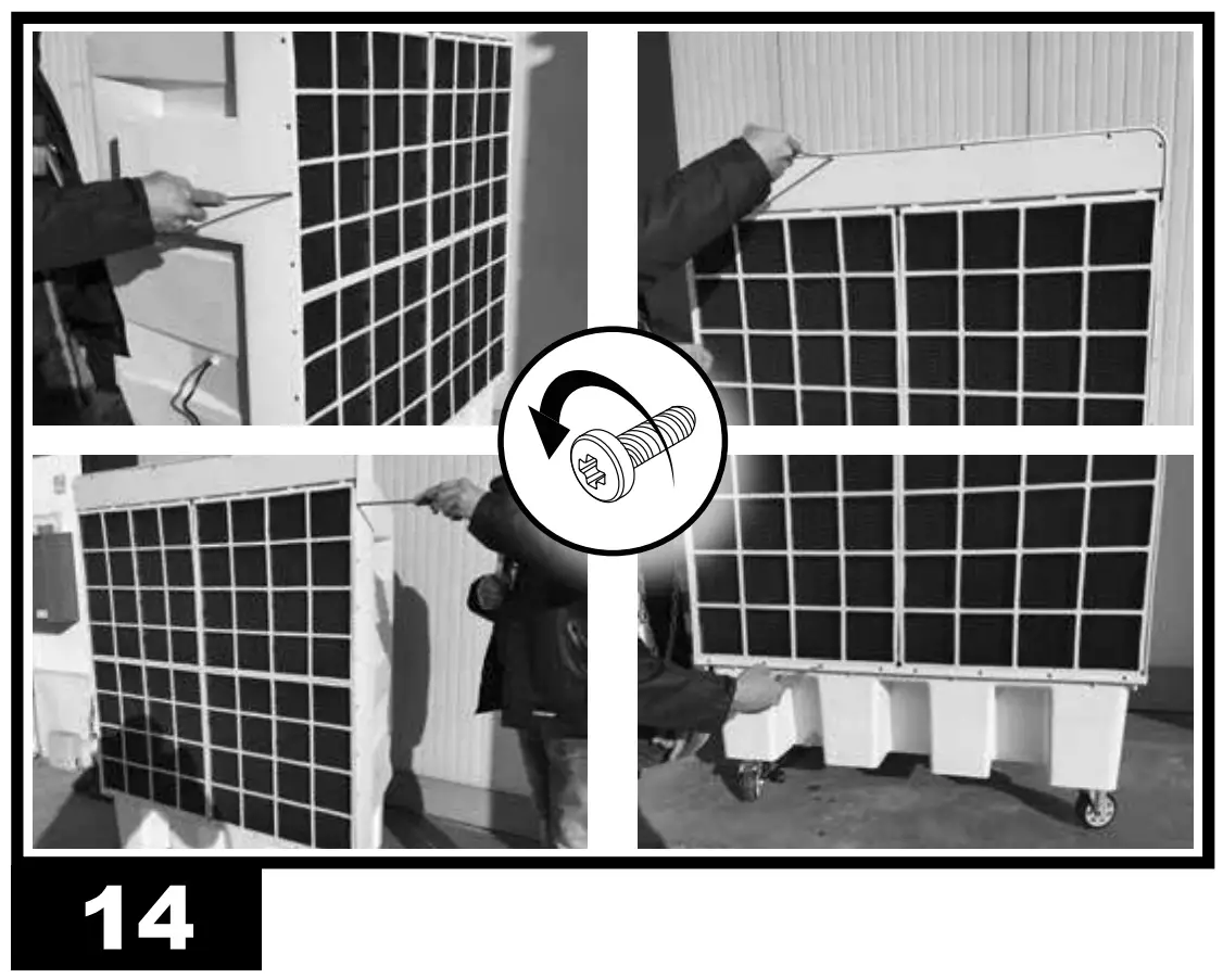
- Remove the fastening screws and then the filter (Fig. 14).
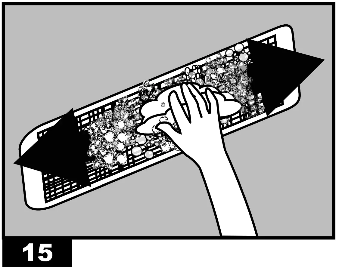
- Clean the filters using a mild detergent and a clean cloth (Fig.15). 15). Make sure that the filter is perfectly dry.
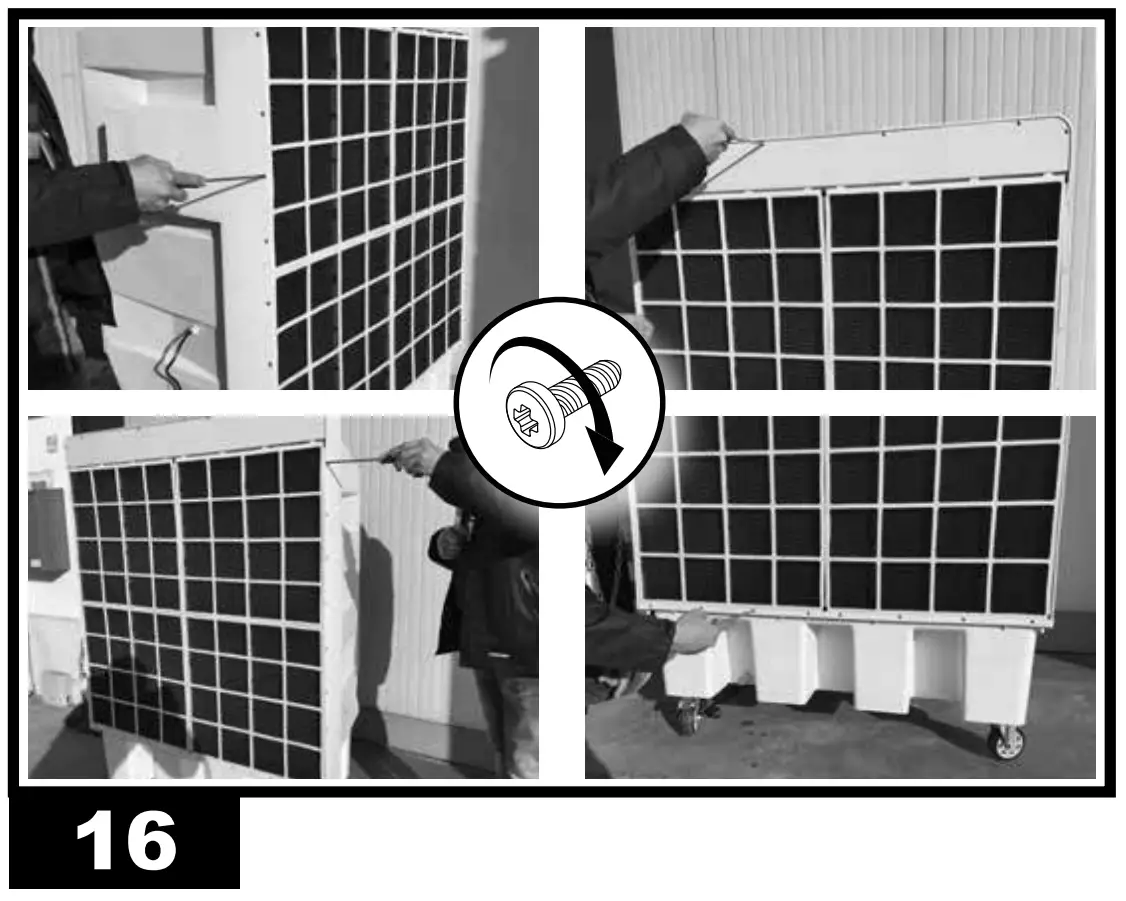
- Reposition the filter and secure it with the screws (Fig. 16)
WATER CIRCUIT:
- To ensure proper operation of the cooler, turn off COOL mode a few minutes before completely switching off the appliance, in order to avoid stagnant water.
- Once a month we recommend performing a complete cycle using clean water and appropriate disinfection products, running the cooler outdoors.
REMOTE HUMIDISTAT CONNECTION (optional)
A remote humidistat can be connected in series to the power supply plug, to manage automatic switch-on or switch-off of the cooler.
After the humidistat has been activated, during normal operation, the cooler switches off. The re-ignition is automatic and the operating configuration is restored keeping the settings prior to switch-off.
CAUTION: THE ONLY SETTING THAT IS NOT RESTORED IS THE “TIMER” FUNCTION, IN THIS CASE IN FACE THE COOLER WILL GO IN STAND-BY CONDITION.
TROUBLESHOOTING
| FAULT | CAUSE | SOLUTION |
| The display does not work |
| 1a. Make sure that the device is con- nected to the power supply 1b. Contact a support centre 2. Contact a support centre |
| There is no air flow or it is very low |
| 1a. Keep the rear of the equipment away from walls that may obstruct the airflow 1b. Remove any objects from the air vent 1c. Contact a support centre 2. Contact a support centre |
| The device does not respond to the commands |
|
|
| The device leaks water |
|
|
TECHNICAL DATA
| MODEL | COLD 120 |
 | 12.000 m³/h-м³/ч |
 | 60 l-л |
|
| 220-240 V-В 50 Hz-Гц 2,7 A 400 W-Вт |
 | 45 kg-кг |
| IPX1 |

| IMPORTANT: In order to have a correct function you must use an electrical generator in class G3 or more (frequency variation ±1%, tension variation ±2%). The maximum power of electrical generator must be three time the nominal power of device that you must connect. |
WIRING DIAGRAMS
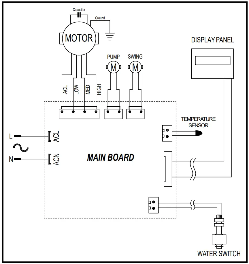
MODELE COLD 120
UNIT 1
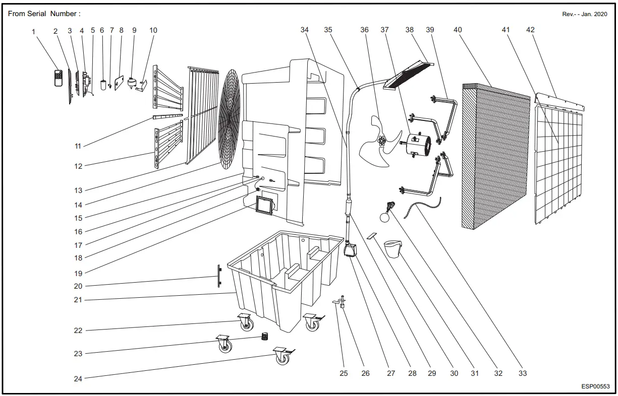
| Pos. | Code N° | Description EN |
| 1 | 4141.160 | REMOTE CONTROL |
| 2 | 4141.161 | CONTROL PANEL |
| 3 | 4141.162 | DISPLAY BOARD |
| 4 | 4141.163 | PC BOARD |
| 5 | 4141.164 | TEMPERATURE SONDE |
| 6 | 4141.165 | CAPACITOR |
| 7 | 4141.166 | CAPACITOR PLATEN |
| 8 | 4141.167 | SWING MOTOR COVER |
| 9 | 4141.168 | SWING MOTOR |
| 10 | 4141.169 | SWING MOTOR PLATEN |
| 11 | 4141.170 | MIDDLE SUPPORT |
| 12 | 4141.171 | OUTSIDE SWING BLADE |
| 13 | 4141.172 | INSIDE SWING BLADE |
| 14 | 4141.173 | FRONT MESH |
| 15 | 4141.174 | COOLING CASING |
| 16 | 4141.175 | CABLE REEL |
| 17 | 4141.176 | WIRE RING |
| 18 | 4141.177 | ELECTRIC WIRE |
| 19 | 4141.178 | WATER INLET HOLE |
| 20 | 4141.179 | WATER LEVEL DISPLAYER |
| 21 | 4141.180 | WATER TANK |
| 22 | 4141.181 | FRONT WHEEL(5”) |
| 23 | 4141.182 | DRAIN VALVE |
| 24 | 4141.183 | BACK WHEEL(5”) |
| 25 | 4141.184 | WATER LEVEL SENSOR FIXTURE |
| 26 | 4141.185 | WATER LEVEL SENSOR |
| 27 | 4141.186 | WATER PUMP |
| 28 | 4141.187 | STAINLESS CLIP |
| 29 | 4141.188 | UV LAMP |
| 30 | 4141.189 | WATER PUMP PLATEN |
| 31 | 4141.190 | PUMP FILTER |
| 32 | 4141.191 | METAL FLOAT |
| 33 | 4141.192 | FLEXIBLE CABLE TIE |
| 34 | 4141.193 | WATER PIPE |
| 35 | 4141.194 | PIPE CLAMP |
| 36 | 4141.195 | FAN |
| 37 | 4141.196 | FAN MOTOR |
| 38 | 4141.197 | WATER DISTRIBUTOR |
| 39 | 4141.198 | FAN BRACKET |
| 40 | 4141.199 | COOLING PAD |
| 41 | 4141.200 | DUST-PROOF NET |
| 42 | 4141.201 | COOLING PAD FASTEN SHEET |
DISPOSAL OF THE PRODUCT
-This product has been designed and manufactured with top-quality materials and components, which can be re-cycled and re-used.
-When a crossed-wheelie bin symbol is attached to the product, it means that the product is protected by the, 2012/19/UE European Directive.
-Please obtain information regarding the local differentiated collection system for electrical and electronic products.
-Respect local Standards in force and do not dispose of old products as normal domestic waste. Correct disposal of the product helps to prevent possible negative consequences for health, the environment and mankind.