![]() SF-150 Radiant Heater
SF-150 Radiant Heater
User Manual
SF-150 Radiant Heater
| Symptom | Possible Cause | Corrective Action |
| 1.Will not start. | Main electrical power circuit breaker tripped | Reset breaker |
| Optional thermostat turned down or improperly installed/defective | Turn thermostat up, check for loose wires and test components and replace if needed. | |
| Primary control safety tripped/defective | Reset/test components, replace if needed | |
| Too much light showing on CAD cell/defective | Eliminate light to CAD cell/test component | |
| Tip switch contacts are closed | If plugged in, verify amber light is on. If not, it is a tip switch issue. Make sure SunFire unit is level. If level, tip switch may be defective and need replacement. | |
| 2.Attempts to fire but does not establish a flame | Low fuel | Add fuel to tank |
| Contaminated fuel | Drain fuel by removing plug on bottom of fuel tank, clean, retighten plug, and fill with clean fuel. | |
| Clogged nozzle/Dirty fuel filter | Repalce nozzle/fuel filter | |
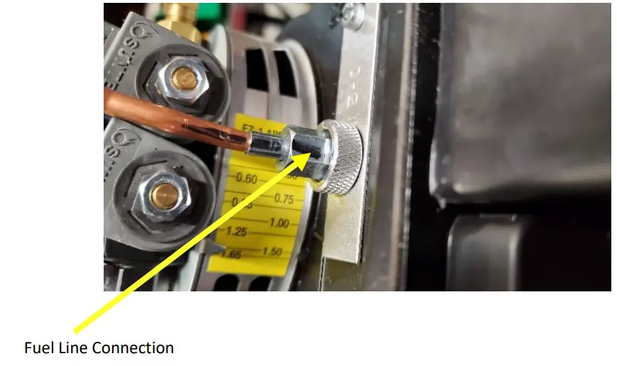
| Air bubble in fuel line | Can sometimes be cleared by starting 3-4 times. Or fix using the following process. Step 1: Open burner control housing. Step 2: Loosen nut that holds copper fuel line to the ignitor box See Fig. 7-1. Step 3: Hold a rag around loosened nut to catch fuel. Step 4: Turn unit “on”. At 15 seconds the solenoid will open from the pump and fuel will pour out. Catch fuel in rage and immediately turn unit off. Step 5: Re-tighten copper fuel line and re-test heater. Also Inspect fuel filter assembly and hose connections for air gaps if not tight or stripped or for possible cracks in the hose. |
| Symptom | Possible Cause | Corrective Action |
| 2.Attempts to fire but does not establish a flame – cont’d | Electrodes not sparking | Through front heat dome, look for sparking when turning unit on. Clean or replace electrodes. |
| Clogged nozzle or defective fuel pump. | Replace nozzle by removing burner from cone assembly. Or replace defective fuel pump. | |
| 3.Fires and then fails Only if fails contintually within | CAD cell is dirty | Clean CAD cell with cloth. If issue still pursists see below. |
| 30 seconds | ||
| CAD Cell is misaligned | Test CAD cell by slightly adjusting position a few times. If issue pursists, see below. | |
| CAD cell is defective | Test by using a jump wire from terminal Fl to terminal F2 on the primary control with the following process. Step 1: Hook jumper to Fl. Step 2: Start unit and wait until flame is present. Step 3: Then immediately hook jump wire to F2. If unit continues to run after 1 minute, CAD cell is defective and needs to be repalced. WARNING: THIS IS FOR TESTING PURPOSES ONLY. FOR SAFETY, DO NOT CONTINTUE TO OPERATE USING JUMP WIRES. | |
| Burner settings may need adjustment. | Test burner. Remove burner housing panel to access the burner. Start the SunFire and view the LED lights to the right of the burner primary control. If green light continues to blink, an adjustment may be needed. Adjust the top fuel pressure screw along with very slight adjustements to the air band until a correct adjustment is achieved and the green light stays solid green. |
| Symptom | Possible Cause | Corrective Action |
| 4.Fires and then fails Only if fails after at least 30 | Contaminated fuel supply | Drain tank from side plug, clean, and fill with clean fuel. |
| seconds with a flame | ||
| Dirty fuel filter | Clean and replace filter | |
| Improper air flow causing a poor flame. The CAD cell may shut unit off with a poor flame. | Adjust air band setting to 1.50 and test flame. See air band adjustement on Figure 3-1. | |
| Plugged nozzle or pre-heater assembly | Clean or replace nozzle | |
| Improper power supply | If using agenerator, run for 20 minutes and retry. Try a clean or different power supply. | |
| Slight haze or dust build up on CAD cell. | Wipe off CAD cell eye with a rag and restart. you may need to click reset button. | |
| 5.Black smoke or whisking Whisking – flames protrude | Nozzle is dirty or clogged | Replace nozzle |
| Improper Air flow | Adjust air band to 1.5 position | |
| through holes in dome face | ||
| Improper fuel flow rate | Adjust fuel flow rate Only after replacing nozzle | |
| 6.Runs briefly on a generator and shuts off | Generator is low on charge | Run generator for 20 minutes, then plug in SunFire unit and restart. |
| 7.Amber lamp does not light | Loose wires | Check all power and tip-switch wires for cut or loose wires and secure or fix if needed. |
| Tip switch is closed | Level SunFire or replace tip switch. | |
| Bad Light | Replace light | |
| Defective primary control circuit board | Replace primary control | |
| 8.Won’t fire If using a thermostat | Check temperature setting. | Set thermostat to a higher temperature if desired. |
| Check for loose wires | Tighten wires for improved connection to thermostat. | |
| Defective thermostat | Replace thermostat. Note: Thermostat must not | |
| require an external 24V power | ||
| source – if used it will damage | ||
| the primary. | ||
| Symptom | Possible Cause | Corrective Action |
| 9.No green light calling for heat when unit is turned on | Check the reset button | Push and hold the reset button |
| If using thermostat | See #8 above | |
| Defective Primary | Replace primary | |
| 10.Bad flame | Clogged Nozzle | Soak Nozzle in parts cleaner/degreaser and blow it out. Or replace nozzle. |
| Dirty/poor fuel | drain fuel and add new clean fuel. | |
| Clogged/dirty filter | Replace filter | |
| 11.Smoky flame | Open transformer lid | Make sure lid is closed |
| Diesel treatment was used | Add clean fuel to decrease treatment ratio, or drain all fuel and replace with new fuel and clean diesel treatment. | |
| Air flow is restricted | Check air band and increase the air flow until smoke is no longer visible. | |
| Improper seal between fuel fliter and filter assembly. | Check the seal on the fuel filter to make sure there are no obstructions between the filter and the filter assembly that could allow air to become mixed in the fuel, causing an improper fuel mixture. | |
| Bad fuel | Drain fuel from tank and add new clean fuel. | |
| 12.No flame | No fuel | Add fuel |
| fuel is not spraying | There are multiple possibilities. Call your distributor or the manufcturer at (855) 251-1649 for instructions. | |
| Vaccum leak | Check hoses for leaks and tighten or replace. | |
| Other issues | We are here to assist you. | Call us at (855) 251-1649 |
HELPFUL SERVICE MANUAL IMAGES
FIGURE 1-1 Burner Housing/Control Box
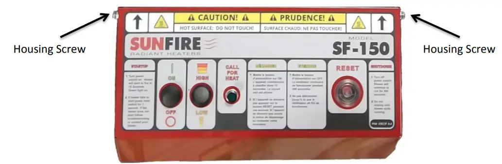
FIGURE 1-2 Burner Pressure Valves
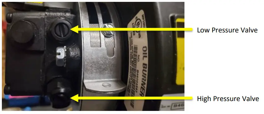
Note: Turn right for more fuel flow and left for less fuel.
FIGURE 1-3 Igniter Assembly
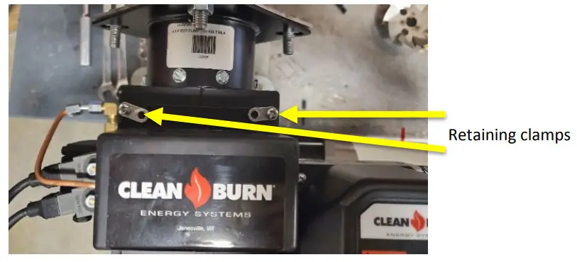
Note: Loosen screws and turn clamps to open igniter assembly.
FIGURE 2-1 CAD Cell
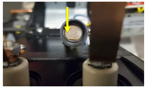
FIGURE 2-2 Inside igniter box
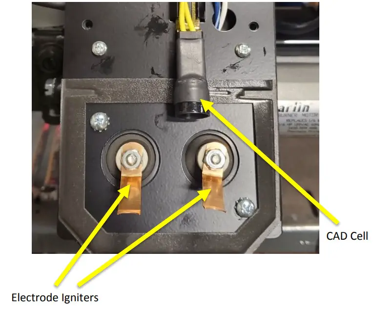
Note: If there is excessive dust while running the SunFire, the inside area of the igniter box should be inspected and cleaned periodically.
Dust can build and causing the unit to turn of prematurely from dust build up on the CAD cell, which will shut the unit off for safety as the flame will not be visible and the electrodes may not receive a proper spark If igniters are dirty. If dirty, simply clean with cloth.
FIGURE 3-1 Air Band 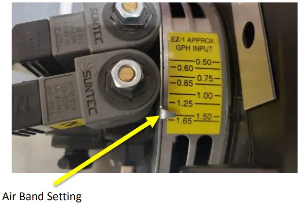
Note: The Air band should be set to approximately 1.25 – 1.5. Reducing the air band to a lower level will reduce the amount of airflow to the flame giving a higher concentration level of fuel that will raise the temperature of the SunFire. However, if reduced too low, it can cause whisking – see Figures 4-1&2 for examples. Reducing too low can become dangerous. This can easily be solved by increasing the amount of air within the flame by increasing the level of the air band.
If the air band level is set too low, upon start up, you may notice some smoke and a more noticeable smell of diesel.
FIGURE 4-1 Primary Control
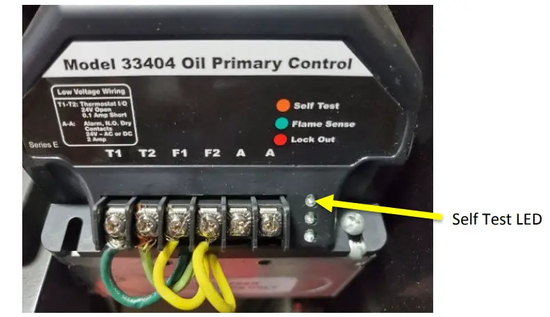
Note: Will blink for a second before the green flame sense light turns no. This simply let’s you know the unit has been turned on and will be calling for heat to produce a flame.
FIGURE 4-2 Primary Control
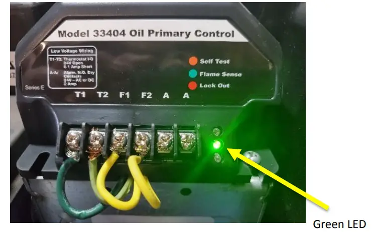
Note: A green light that blinks indicates potential issues with the flame not running efficiently. Check symptoms and causes on previous pages. If green light remains solid, the flame is running correctly. If flame gets just a little worse, it will shut the heater off. It will auto-restart one more time and if it happens again,it will go into lockout and you will need to hit the reset button to restart.
FIGURE 4-3 Primary Control
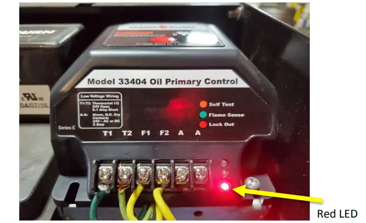
Note: If red “locked out” light is on, the control has failed to sense a flame after two attempts to fire and the reset button must be pressed before attempting to start again. When unit is turned on and does not fire on first attempts, this light will blink for 45 seconds. A 2nd attempt will be made and if no flame is sensed, the light will turn solid until the reset button is pushed.
FIGURE 5-1 Minor Whisking 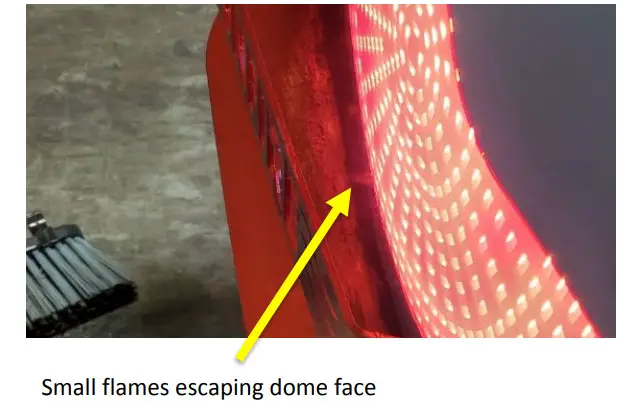
Note: It is recommended to increase the air band setting to approximately 1.50 and reduce the fuel flow on the high pressure valve if necessary.
FIGURE 5-2 Severe Whisking
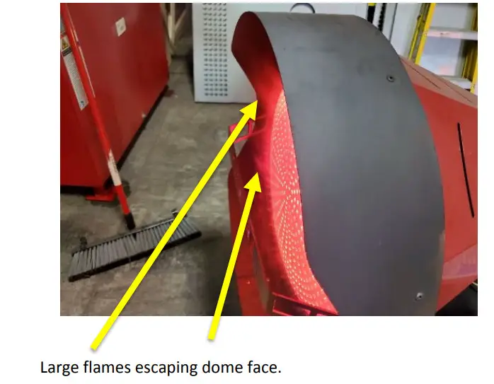
Warning: This is can be dangerous at these levels. It is recommended to immediately increase the air band setting to approximately 1.50 and reduce the fuel flow on the high pressure valve.
FIGURE: 6-1 View Inside Cone of Nozzle/Flame Assembly
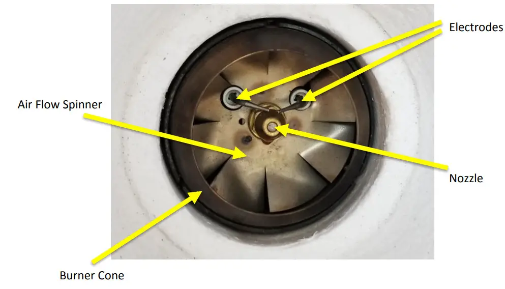
Note: It is important that the nozzle and electrodes remain free from excessive build-up. Clean if necessary or replace nozzle. It is critical to never run the unit without the burner cone in place to produce a proper flame.
FIGURE: 7-1 Copper fuel line in Burner Assembly
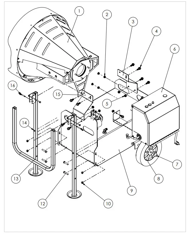
| ITEM NO. | PART NUMBER | DESCRIPTION | QTY. |
| 1 | 29462 | SUNFIRE DOME ASSEMBLY | 1 |
| 2 | 34099 | NUT 5/16-18 SERR FLANGE | 4 |
| 3 | 29468 | SUNFIRE RIGHT LOWER STRAP | 1 |
| 4 | 34502 | SCREW 3/8-16X1″ HEX | 9 |
| 5 | 34009 | NUT 3/8-16 FLANGE | 4 |
| 6 | 29463 | SF-150 BURNER | 1 |
| 7 | 34505 | 5/8 PUSH ON WHEEL RETAINER | 2 |
| 8 | 29518 | WHEEL 10X2.75 HUB2.25 | 2 |
| 9 | 29467 | SUNFIRE TANK ASSEMBLY | 1 |
| 10 | 7202 | NUT 3/8-16 HEX | 4 |
| 11 | 29465 | SUNFIRE LIFTING HANDLE ASSEMBL | 2 |
| 12 | 34514 | SCREW 3/8-16 X 1-1/2 HH ZN | 4 |
| 13 | 29492 | HINGE HANDLE | 1 |
| 14 | 34516 | BUMPER SELF ADHESIVE SF-150 | 2 |
| 15 | 29469 | SUNFIRE LEFT LOWER STRAP | 1 |
| 16 | 34515 | PIN QUICK RELEASE 6MM DIA 40M | 2 |
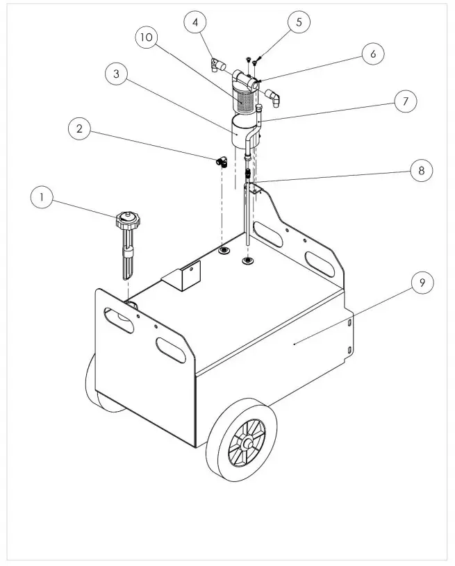
| ITEM NO. | PART NUMBER | DESCRIPTION | BOTTOM HALF/QTY. |
| 1 | 29506 | CAP GAUGE COMBO RAD HEAT 8″ | 1 |
| 2 | 29411 | FING.J1C.ST.H.90ELO6MJ-06MJ | 1 |
| 3 | 29402 | HEATER BAND FOR FUEL FILTER | 1 |
| 4 | 29407 | FING.J1C.ST.H.90ELO6M1-08MP | 2 |
| 5 | 34447 | 1/4-20 x 3/8′ | 2 |
| 6 | 29401 | FUEL FILTER ASSEMBLY | 1 |
| 7 | 29511 | SUCTION LINE HOSE e | 1 |
| 8 | 29484 | RAD HEAT TUBE DRAW ASSEMBLY | 1 |
| 9 | 29467 | SUNFIRE TANK ASSEMBLY | 1 |
| 10 | 37500 | FUEL FILTER REPLACEMENT | 1 |
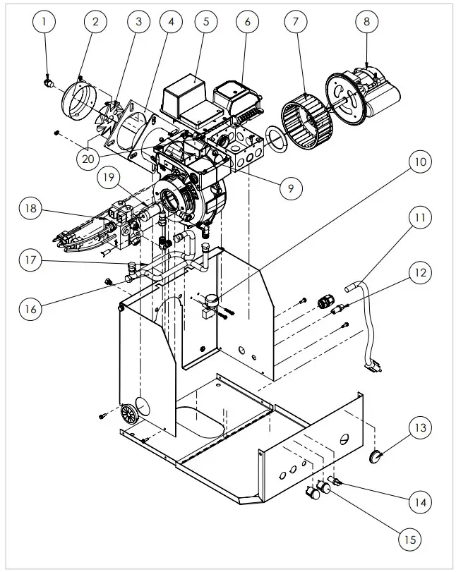
| ITEM NO. | PART NUMBER | DESCRIPTION | QTY. |
| 1 | 13154 | NOZZLE W/CHECK VALVE | 1 |
| 2 | 26669 | RADIANT HEATER BURNER CONE | 1 |
| 3 | 29418 | SPINNER RAD HTR VERSION 2 | 1 |
| 4 | 29459 | FLANGE GASKET RAD HTR | 1 |
| 5 | 81010390 | ELECTRIC IGNITER | 1 |
| 6 | 33404 | SF-ISO PRIMARY | 1 |
| 7 | 29544 | SUNFIRE BURNER BLOWER WHEEL | 1 |
| 8 | 9502 | MOTOR 1/6HP | 1 |
| 9 | 29505 | ELECTRODES | 2 |
| 10 | 29450 | SWITCH TIP RAD HEATER | 1 |
| 11 | 29437 | CORD POWER RAD HTR | 1 |
| 12 | 33168 | LED AMBER LIGHT | 1 |
| 13 | 35408 | PLUG RUBBER RESET RADIANT HEAT | 1 |
| 14 | 33169 | LED GREEN LIGHT | 1 |
| 15 | 29449 | SWITCH ON/OFF HI/LOW RAD HTR | 2 |
| 16 | 29513 | FILTER TO BURNER HOSE 10.5′ | 1 |
| 17 | 29512 | RETURN FROM BURNER TO TANK 13.5′ | I |
| 18 | 29460 | PUMP HEAD RADIANT HEATER | 1 |
| 19 | 29523 | COUPLER BURNER RAIDANT HEATER | I |
| 20 | 8981 | CAD CELL | 1 |
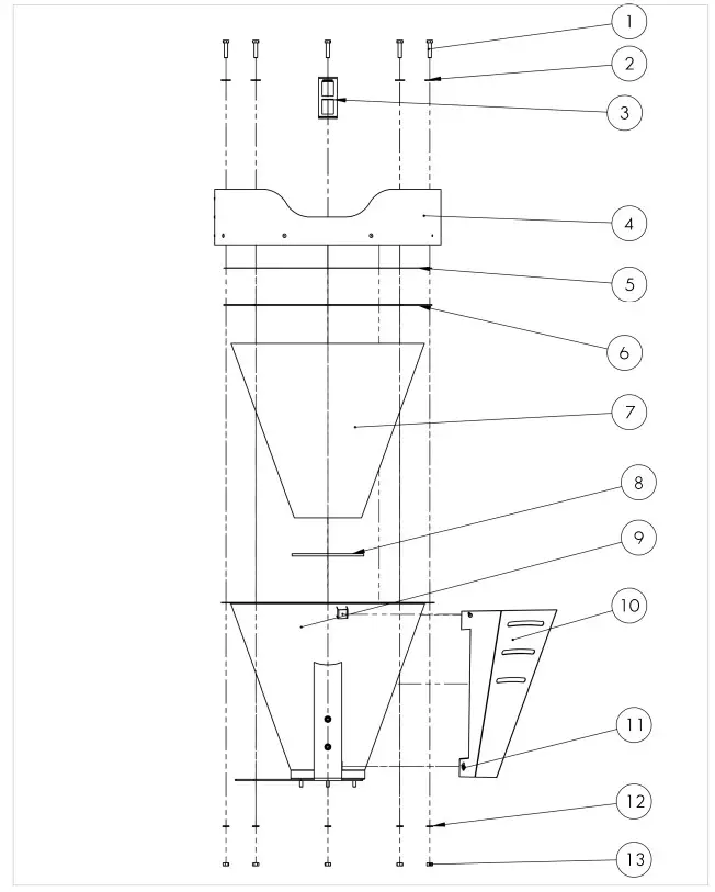
| ITEM NO. | PART NUMBER | DESCRIPTION | QTY. |
| 1 | 34457 | SCREW 3/8-16 X 1-1/2 HH | 8 |
| 2 | 34400 | 3/8 FLAT WASHER – SS | 8 |
| 3 | 29472 | FLAME GUARD | 1 |
| 4 | 29487 | ROLLED SHROUD ASSEMBLY | 1 |
| 5 | 29471 | DOME PUNCHED FACE | 1 |
| 6 | 29542 | RADIANT HEATER TOP GASKET | 1 |
| 7 | 29508 | SUNFIRE DOME INSULATION | 1 |
| 8 | 29499 | INSULATION DOME GASKET | 1 |
| 9 | 29507 | SUNFIRE SPUN DOME WITH BRACKET SUPPORTS | 1 |
| 10 | 29495 | SF HEAT SHEILD | 1 |
| 11 | 34116 | 10 X 5/8 HEX WASHER HEAD TEK Z | 4 |
| 12 | 34399 | 3/8 SPLIT LOCK WASHER – SS | 8 |
| 13 | 34010 | 3/8-16 BRASS HEX NUT | 8 |