
TKBHome
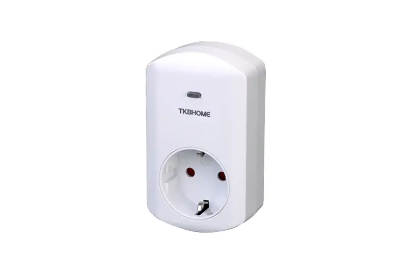
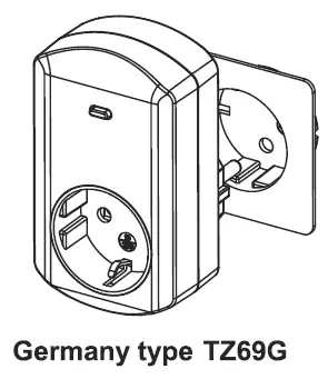
Smart energy plug in switch
SKU: TKBETZ69-G

Quickstart
This is a
On/Off Power Switch
for
Europe.
To run this device please connect it to your mains power supply.
To add this device to your network execute the following action:
Press the socket on/off button three times within 1.5 seconds will be included
Important safety information
Please read this manual carefully. Failure to follow the recommendations in this manual may be dangerous or may violate the law.
The manufacturer, importer, distributor and seller shall not be liable for any loss or damage resulting from failure to comply with the instructions in this manual or any other material.
Use this equipment only for its intended purpose. Follow the disposal instructions.
Do not dispose of electronic equipment or batteries in a fire or near open heat sources.
What is Z-Wave?
Z-Wave is the international wireless protocol for communication in the Smart Home. This
device is suited for use in the region mentioned in the Quickstart section.

Z-Wave ensures a reliable communication by reconfirming every message (two-way
communication) and every mains powered node can act as a repeater for other nodes
(meshed network) in case the receiver is not in direct wireless range of the
transmitter.
This device and every other certified Z-Wave device can be used together with any other
certified Z-Wave device regardless of brand and origin as long as both are suited for the
same frequency range.
If a device supports secure communication it will communicate with other devices
secure as long as this device provides the same or a higher level of security.
Otherwise it will automatically turn into a lower level of security to maintain
backward compatibility.
For more information about Z-Wave technology, devices, white papers etc. please refer
to www.z-wave.info.
Product Description
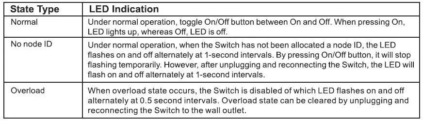
It is able to detect current wattage(5-3000W) and overload wattage(3010-3300W) of connected lights or appliances. When detecting overload state, the switch will be disabled and its on/off button will be lockout of which LED will flash quickly. However, unplug and re-connect the switch will reset its overload condition to normal status.
Prepare for Installation / Reset
Please read the user manual before installing the product.
In order to include (add) a Z-Wave device to a network it must be in factory default
state. Please make sure to reset the device into factory default. You can do this by
performing an Exclusion operation as described below in the manual. Every Z-Wave
controller is able to perform this operation however it is recommended to use the primary
controller of the previous network to make sure the very device is excluded properly
from this network.
Reset to factory default
This device also allows to be reset without any involvement of a Z-Wave controller. This
procedure should only be used when the primary controller is inoperable.
1. To reset, press the socket on/off button three times within 1.5 seconds”
2. then the fourth time, press and hold for seconds until the socket LED is off”
3. the socket reset successfully Use the “Reset” procedure only in the event that the network primary controller is missing or otherwise inoperable
Safety Warning for Mains Powered Devices
ATTENTION: only authorized technicians under consideration of the country-specific
installation guidelines/norms may do works with mains power. Prior to the assembly of
the product, the voltage network has to be switched off and ensured against re-switching.
Installation
Plug this On/OFF Switch into a wall outlett.
Inclusion/Exclusion
On factory default the device does not belong to any Z-Wave network. The device needs
to be added to an existing wireless network to communicate with the devices of this network.
This process is called Inclusion.
Devices can also be removed from a network. This process is called Exclusion.
Both processes are initiated by the primary controller of the Z-Wave network. This
controller is turned into exclusion respective inclusion mode. Inclusion and Exclusion is
then performed doing a special manual action right on the device.
Inclusion
Press the socket on/off button three times within 1.5 seconds will be included
Exclusion
Press the socket on/off button three times within 1.5 seconds will be excluded
Product Usage
LED Indication
To distinguish what mode he switch is in, view from the LED for identification
Choosing a Suitable Location
1. Do not locate the switch facing direct sinlight, humid or dusty place.
2. The suitable ambient temperature for the switch is 0-40″°C
3. Do not locate the switch whre exists combusible substances or any source of heat, e.g. fires, radiators, boiler ect.
4. After putting into use. the body of switch will become a little bit hot of which phenomenon is normal.
Quick trouble shooting
Here are a few hints for network installation if things dont work as expected.
- Make sure a device is in factory reset state before including. In doubt exclude before include.
- If inclusion still fails, check if both devices use the same frequency.
- Remove all dead devices from associations. Otherwise you will see severe delays.
- Never use sleeping battery devices without a central controller.
- Dont poll FLIRS devices.
- Make sure to have enough mains powered device to benefit from the meshing
Association – one device controls an other device
Z-Wave devices control other Z-Wave devices. The relationship between one device
controlling another device is called association. In order to control a different
device, the controlling device needs to maintain a list of devices that will receive
controlling commands. These lists are called association groups and they are always
related to certain events (e.g. button pressed, sensor triggers, …). In case
the event happens all devices stored in the respective association group will
receive the same wireless command wireless command, typically a ‘Basic Set’ Command.
Association Groups:
Group NumberMaximum NodesDescription
| 1 | 5 | Lifeline |
Configuration Parameters
Z-Wave products are supposed to work out of the box after inclusion, however
certain configuration can adapt the function better to user needs or unlock further
enhanced features.
IMPORTANT: Controllers may only allow configuring
signed values. In order to set values in the range 128 … 255 the value sent in
the application shall be the desired value minus 256. For example: To set a
parameter to 200 it may be needed to set a value of 200 minus 256 = minus 56.
In case of a two byte value the same logic applies: Values greater than 32768 may
needed to be given as negative values too.
Parameter 1: Change the state of indicator light
Size: 1 Byte, Default Value: 0
SettingDescription
| 0 | On -> LED ON |
| 1 | Off -> LED ON |
Parameter 2: Memory function
Size: 1 Byte, Default Value: 0
SettingDescription
| 0 | Disable |
| 1 | Enable |
Parameter 3: Watt Meter Report Period
If the setting configured for 1 hour (set value = 720), the TZ69 will report its instant power consumtion every 1 hour to Z-Wave Controller. The maximum interval to report its instand power consumption is 45 hours.
Size: 2 Byte, Default Value: 720
SettingDescription
| 1 – 32767 | Time in 5 second steps |
Parameter 4: KWH Meter Report Period
If the setting configured for 1 hour (set value = 6), the TZ69 will report its accumulated power consumtion every 1 hour to Z-Wave Controller. The maximum interval to report its instand power consumption is 227,55 Days.
Size: 2 Byte, Default Value: 6
SettingDescription
| 1 – 32767 | Time in 10 minutes steps |
Parameter 5: Threshold of Watt for Load Caution
In the above form, when the value is 3000, if Relay 1 load by below 3000 watt turned into more than 3000 watt, will immediately send the instantaneous load w value to Group 1.
Size: 2 Byte, Default Value: 3000
SettingDescription
| 10 – 3000 | Threshold Watt |
Parameter 6: Thresold of KWH for Load Caution
In the above form, when the value is 10000, if Relay 1 load by below 3000 watt, when the accumulation of Relay 1 consumed power more than 10000 KWH, will immediately send the accumulation of current consumed power to Group 1.
Size: 2 Byte, Default Value: 10000
SettingDescription
| 1 – 10000 | Thresold in KWH |
Technical Data
| Dimensions | 0.0596300×0.0743500×0.1016200 mm |
| Weight | 123.99 gr |
| Hardware Platform | ZM5202 |
| EAN | 6959174469769 |
| IP Class | IP 20 |
| Voltage | 230V |
| Load | 3000 W |
| Device Type | On/Off Power Switch |
| Network Operation | Always On Slave |
| Z-Wave Version | 6.51.06 |
| Certification ID | ZC10-16010014 |
| Z-Wave Product Id | 0x0118.0x0004.0x0002 |
| Frequency | Europe – 868,4 Mhz |
| Maximum transmission power | 5 mW |
Supported Command Classes
- Switch All
- Association
- Association Group Information
- Basic
- Configuration
- Device Reset Locally
- Firmware Update Md V2
- Manufacturer Specific
- Meter
- Proprietary
- Switch Binary
- Version
- Zwaveplus Info
Explanation of Z-Wave specific terms
- Controller — is a Z-Wave device with capabilities to manage the network.
Controllers are typically Gateways,Remote Controls or battery operated wall controllers. - Slave — is a Z-Wave device without capabilities to manage the network.
Slaves can be sensors, actuators and even remote controls. - Primary Controller — is the central organizer of the network. It must be
a controller. There can be only one primary controller in a Z-Wave network. - Inclusion — is the process of adding new Z-Wave devices into a network.
- Exclusion — is the process of removing Z-Wave devices from the network.
- Association — is a control relationship between a controlling device and
a controlled device. - Wakeup Notification — is a special wireless message issued by a Z-Wave
device to announces that is able to communicate. - Node Information Frame — is a special wireless message issued by a
Z-Wave device to announce its capabilities and functions.


