 AOC Q2790PQ LED Backlight LCD Monitor
Safety
National Conventions
The following subsections describe the notational conventions used in this document.
Notes Cautions, and Warnings
Throughout this guide, blocks of text may be accompanied by an icon and printed in bold type or in italic type. These blocks are notes, cautions, and warnings, and they are used as follows:
NOTE:
A NOTE indicates important information that helps you make better use of your computer system.
CAUTION:
A CAUTION indicates either potential damage to hardware or loss of data and tells you how to avoid the problem.
WARNING:
A WARNING indicates the potential for bodily harm and tells you how to avoid the problem. Some warnings may appear in alternate formats and may be unaccompanied by an icon. In such cases, the specific presentation of the warning is mandated by regulatory authority.
Power
The monitor should be operated only from the type of power source indicated on the label. If you are not sure of the type of power supplied to your home, consult your dealer or local power company.The monitor is equipped with a three-pronged grounded plug, a plug with a third (grounding) pin. This plug will fit only into a grounded power outlet as a safety feature. If your outlet does not accommodate the three-wire plug, have an electrician install the correct outlet, or use an adapter to ground the appliance safely. Do not defeat the safety purpose of the grounded plug. Unplug the unit during a lightning storm or when it will not be used for long periods of time. This will protect the
monitor from damage due to power surges. Do not overload power strips and extension cords. Overloading can result in fire or electric shock. To ensure satisfactory operation, use the monitor only with UL listed computers which have appropriate configured receptacles marked between 100-240V AC, Min. 5A.The wall socket shall be installed near the equipment and shall be easily accessible. For use only Awith the attached power adapter
Installation
Do not place the monitor on an unstable cart, stand, tripod, bracket, or table. If the monitor falls, it can injure a person and cause serious damage to this product. Use only a cart, stand, tripod, bracket, or table recommended by the manufacturer or sold with this product. Follow the manufacturer’s instructions when installing the product and use mounting accessories recommended by the manufacturer. A product and cart combination should be moved with care.
Never push any object into the slot on the monitor cabinet. It could damage circuit parts causing a fire or electric shock. Never spill liquids on the monitor. Do not place the front of the product on the floor. If you mount the monitor on a wall or shelf, use a mounting kit approved by the manufacturer and follow the kit instructions. Leave some space around the monitor as shown below. Otherwise, air circulation may be inadequate hence overheating may cause a fire or damage to the monitor. See below the recommended ventilation areas around the monitor when the monitor is installed on the wall or on the stand:
Installed with sand installed 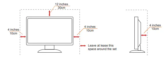
Cleaning
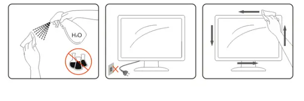
Clean the cabinet regularly with cloth. You can use soft detergent to wipe out the stain, instead of strong detergent which will cauterize the product cabinet.When cleaning, make sure no detergent is leaked into the product. The cleaning cloth should not be too rough as it will scratch the screen surface.Please disconnect the power cord before cleaning the product.
Other
If the product is emitting a strange smell, sound or smoke, disconnect the power plug IMMEDIATELY and contact a Service Center.Make sure that the ventilating openings are not blocked by a table or curtain.Do not engage the LCD monitor in severe vibration or high impact conditions during operation. Do not knock or drop the monitor during operation or transportation.
Setup
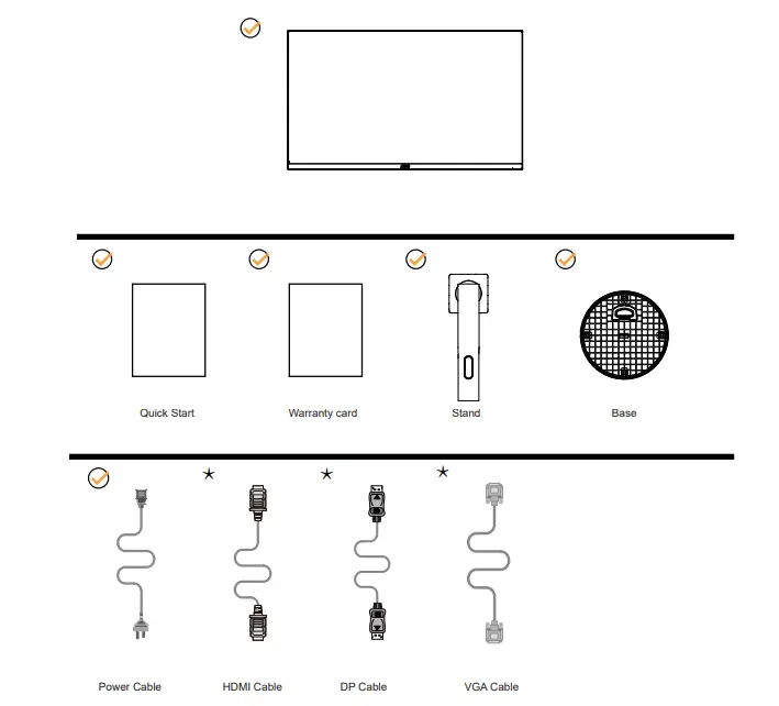
Contents in Box
Not all signal cables will be provided for all countries and regions. Please check with the local dealer or AOC branch office for confirmation
Setup Stand & Base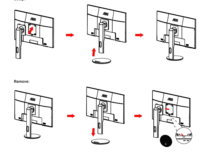
Please setup or remove the base following the steps as below.
Setup:
Adjusting Viewing Angle
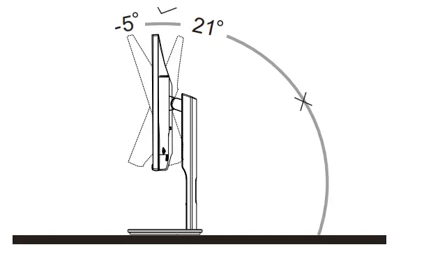
For optimal viewing it is recommended to look at the full face of the monitor, then adjust the monitor’s angle to your own preference. Hold the stand so you will not topple the monitor when you change the monitor’s angle. You are able to adjust the monitor as below:
NOTE:
Do not touch the LCD screen when you change the angle. It may cause damage or break the LCD screen.
Connecting the Monitor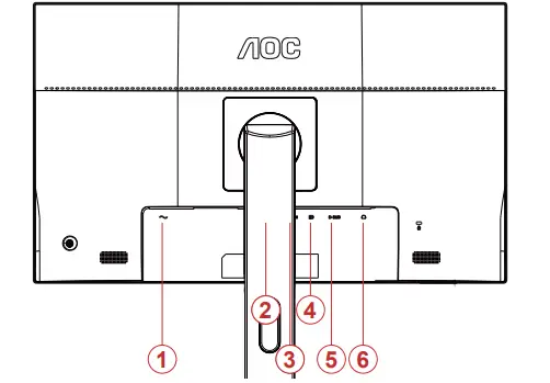
Cable Connections In Back of Monitor and Computer:
- Power
- HDMI 1
- HDMI 2
- DP
- Analog (D-Sub 15-Pin VGA cable)
- Earphone out
Connect to PC
- Connect the power cord to the back of the display firmly.
- Turn off your computer and unplug its power cable.
- Connect the display signal cable to the video connector on the back of your computer.
- Plug the power cord of your computer and your display into a nearby outlet.
- Turn on your computer and display. If your monitor displays an image, installation is complete. If it does not display an image, please refer Troubleshooting. To protect equipment, always turn off the PC and LCD monitor before connecting.
Adjusting
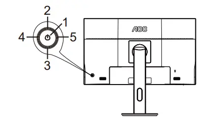
Hotkeys
| 1 | Menu/Enter/ Power |
| 2 | Source/Auto/Exit |
| 3 | ECO |
| 4 | Volume |
| 5 | Clear Vision |
Up/Source/Auto/Exit
When the OSD is closed, press “up” button will be Source hot key function. When the OSD is closed,
press “up” button continuously about 2 second to do auto configure (Only for the models with D-Sub).
Image Ratio/Volume/Right
When there is no OSD, press the “right” key to open the volume adjustment bar, under the HDMI / DP source.
When there is no OSD, press the “right” key to enter the image scale switching function, under the D-SUB signal source (If the product screen size is wide format, the hot key is disable to adjust).
Down/ECO
When there is no OSD, press “down” to active ECO adjustment bar, press left or right to adjust ECO mode.
Power/Menu/Enter
Press the Power button to turn on the monitor.
When there is no OSD, Press to display the OSD or confirm the selection. Press about 2 second to turn off the monitor
Clear Vision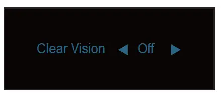
- When there is no OSD, Press the “ ” button to activate Clear Vision.
- Use the “ ” or “ ” buttons to select between weak, medium, strong, or off settings. Default setting is always “off”.

- Press and hold “ ” button for 5 seconds to activate the Clear Vision Demo, and a message of “Clear Vision Demo: on” will be display on the screen for a duration of 5 seconds. Press Menu or Exit button, the message will disappear. Press and hold “ ” button for 5 seconds again, Clear Vision Demo will be off.Clear Vision function provides the best image viewing experience by converting low resolution and blurry images into clear and vivid images.

OSD Setting
Basic and simple instruction on the control keys.
- Press the MENU button to activate the OSD window.
- Press Left or Right to navigate through the functions. Once the desired function is highlighted, press the MENU- button to activate it, press Left or Right to navigate through the sub-menu functions. Once the desired function is highlighted, press MENU button to activate it.
- Press Left or Right to change the settings of the selected function. Press AUTO–button to exit. If you want to adjust
any other function, repeat steps 2-3. - OSD Lock/Unlock Function: OSD Lock Function: To lock the OSD, press and hold the MENU button while the monitor is off and then press power button to turn the monitor on. To un-lock the OSD – press and hold the MENU button while the monitor is off and then press power button to turn the monitor on.
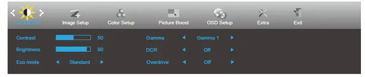
Luminance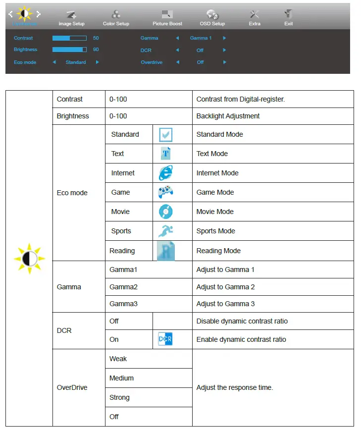
Image Setup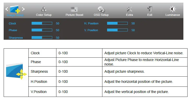
Color Setup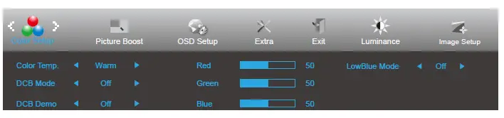
|
|
Color Temp. | Warm | Recall Warm Color Temperature from EEPROM. | |
| Normal | Recall Normal Color Temperature from EEPROM. | |||
| Cool | Recall Cool Color Temperature from EEPROM. | |||
| sRGB | Recall SRGB Color Temperature from EEPROM. | |||
| User | Red | Red Gain from Digital-register | ||
| Green | Green Gain Digital-register. | |||
| Blue | Blue Gain from Digital-register | |||
|
DCB Mode | Full Enhance | on or off | Disable or Enable Full Enhance Mode | |
| Nature Skin | on or off | Disable or Enable Nature Skin Mode | ||
| Green Field | on or off | Disable or Enable Green Field Mode | ||
| Sky-blue | on or off | Disable or Enable Sky-blue Mode | ||
| AutoDetect | on or off | Disable or Enable AutoDetect Mode | ||
| OFF | on or off | Disable or Enable OFF Mode | ||
| DCB Demo | On or off | Disable or Enable Demo | ||
| Red | 0-100 | Red gain from Digital-register. | ||
| Green | 0-100 | Green gain from Digital-register. | ||
| Blue | 0-100 | Blue gain from Digital-register. | ||
|
LowBlue Mode | Multimedia |
Decrease blue light wave by controlling color temperature. | ||
| Internet | ||||
| Office | ||||
| Reading | ||||
| Off | ||||
Picture Boost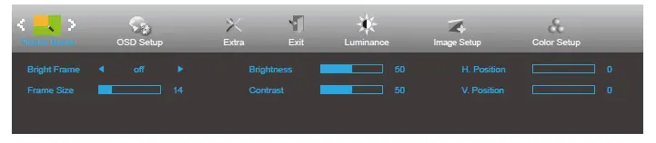
|
| Bright Frame | on or off | Disable or Enable Bright Frame |
| Frame Size | 14-100 | Adjust Frame Size | |
| Brightness | 0-100 | Adjust Frame Brightness | |
| Contrast | 0-100 | Adjust Frame Contrast | |
| H. position | 0-100 | Adjust Frame horizontal Position | |
| V. position | 0-100 | Adjust Frame vertical Position |
Note:
Adjust the brightness, contrast, and position of the Bright Frame for better viewing experience.
OSD Setup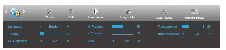
|
| Language | Select the OSD language | |
| Timeout | 5-120 | Adjust the OSD Timeout | |
| DP Capability | 1.1/1.2 | Please be noted that only DP1.2 support FreeSync function | |
| H. Position | 0-100 | Adjust the horizontal position of OSD | |
| V. Position | 0-100 | Adjust the vertical position of OSD | |
| USB | on or off | For model need to turn on/off USB power during power saving | |
| Transparence | 0-100 | Adjust the transparence of OSD | |
| Break Reminder | on or off | Break reminder if the user continuously work for more than 1hrs |
Extra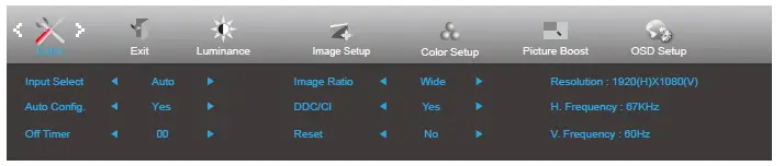
|
| Input Select | Auto/D-SUB/HDMI1/HDMI2/ DP | Select input signal source. |
| Auto Config. | Yes / No | Auto adjust.the picture to default. | |
| Off Timer | 0-24 hrs | Select DC off time. | |
| Image Ratio | Wide / 4:3 / 1:1 / Movie1/ Movie2 | Select Wide / 4:3 / 1:1 / Movie1/ Movie2 format for display. | |
| DDC/CI | Yes / No | Turn on or off DDC/CI Support. | |
| Reset | yes or no | Reset the menu to default. (ENERGY STAR® available for selective models.) | |
| ENERGY STAR® or no |
Exit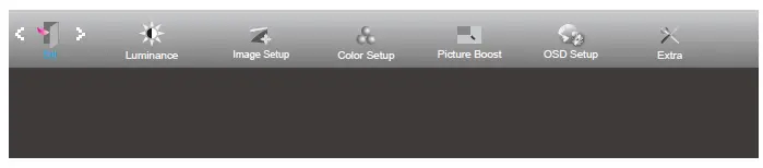
LED Indicator
| Status | LED Color |
| Full Power Mode | White |
| Active-off Mode | Orange |
Troubleshoot
| Problem & Question | Possible Solutions |
| Power LED Is Not ON | Make sure the power button is ON and the Power Cord is properly connected to a grounded power outlet and to the monitor. |
|
No images on the screen | Is the power cord connected properly? Check the power cord connection and power supply. Is the cable connected correctly? (Connected using the VGA cable) Check the VGA cable connection. (Connected using the HDMI cable) Check the HDMI cable connection. (Connected using the DP cable) Check the DP cable connection. * VGA/HDMI/DP input is not available on every model. If the power is on, reboot the computer to see the initial screen (the login screen), which can be seen. If the initial screen (the login screen) appears, boot the computer in the applicable mode (the safe mode for Windows 7/8/10) and then change the frequency of the video card. (Refer to the Setting the Optimal Resolution) If the initial screen (the login screen) does not appear, contact the Service Center or your dealer. Can you see “Input Not Supported” on the screen? You can see this message when the signal from the video card exceeds the maximum resolution and frequency that the monitor can handle properly. Adjust the maximum resolution and frequency that the monitor can handle properly. Make sure the AOC Monitor Drivers are installed. |
| Picture Is Fuzzy & Has Ghosting Shadowing Problem | Adjust the Contrast and Brightness Controls. Press to auto adjust. Make sure you are not using an extension cable or switch box. We recommend plugging the monitor directly to the video card output connector on the back. |
| Picture Bounces, Flickers Or Wave Pattern Appears In The Picture | Move electrical devices that may cause electrical interference as far away from the monitor as possible. Use the maximum refresh rate your monitor is capable of at the resolution you are using. |
|
Monitor Is Stuck In Active Off- Mode” | The Computer Power Switch should be in the ON position. The Computer Video Card should be snugly fitted in its slot. Make sure the monitor’s video cable is properly connected to the computer. Inspect the monitor’s video cable and make sure no pin is bent. Make sure your computer is operational by hitting the CAPS LOCK key on the keyboard while observing the CAPS LOCK LED. The LED should either turn ON or OFF after hitting the CAPS LOCK key. |
| Missing one of the primary colors (RED, GREEN, or BLUE) | Inspect the monitor’s video cable and make sure that no pin is damaged. Make sure the monitor’s video cable is properly connected to the computer. |
| Screen image is not centered or sized properly | Adjust H-Position and V-Position or press hot-key (AUTO). |
| Picture has color defects (white does not look white) | Adjust RGB color or select desired color temperature. |
| Horizontal or vertical disturbances on the screen | Use Windows 7/8/10 shut-down mode to adjust CLOCK and FOCUS. Press to auto-adjust. |
| Regulation & Service | Please refer to Regulation & Service Information which is in the CD manual or www.aoc.com (to find the model you purchase in your country and to find Regulation & Service Information in Support page. |
Specification
General Specification
|
Panel | Model name | Q2790PQ | ||
| Driving system | TFT Color LCD | |||
| Viewable Image Size | 68.6cm diagonal | |||
| Pixel pitch | 0.2331mm(H) x 0.2331mm(V) | |||
| Separate Sync. | H/V TTL | |||
| Display Color | 16.7M Colors | |||
|
Others | Horizontal scan range | 30~99KHz | ||
| Horizontal scan Size(Maximum) | 596.736mm | |||
| Vertical scan range | 50Hz~76Hz | |||
| Vertical Scan Size(Maximum) | 335.664mm | |||
| Optimal preset resolution | 1920×1080@60Hz(VGA) | |||
| Max resolution | 2560×1440@60Hz(HDMI, DP) | |||
| Plug & Play | VESA DDC2B/CI | |||
| Power Source | 100-240V~,50/60Hz | |||
| Power Consumption | Typical(default brightness and contrast) | 33W | ||
| Max. (brightness = 100, contrast =100) | ≤ 48W | |||
| Standby mode | <0.5W | |||
| Physical Characteristics | Connector Type | D-Sub/ HDMI/DP/Earphone out | ||
| Signal Cable Type | Detachable | |||
|
Environmental | Temperature | Operating | 0°~ 40° | |
| Non-Operating | -25°~ 55° | |||
| Humidity | Operating | 10% ~ 85% (non-condensing) | ||
| Non-Operating | 5% ~ 93% (non-condensing) | |||
| Altitude | Operating | 0~ 5000 m (0~ 16404ft ) | ||
| Non-Operating | 0~ 12192m (0~ 40000ft ) | |||
Preset Display Modes
| STANDARD | RESOLUTION | HORIZONTAL FREQUENCY(kHz) | VERTICAL FREQUENCY(Hz) |
| VGA | 640×480@60Hz | 31.469 | 59.94 |
| 640×480@72Hz | 37.861 | 72.809 | |
| 640×480@75Hz | 37.5 | 75 | |
| MAC MODES VGA | 640×480@67Hz | 35 | 66.667 |
| IBM MODE | 720×400@70Hz | 31.469 | 70.087 |
|
SVGA | 800×600@56Hz | 35.156 | 56.25 |
| 800×600@60Hz | 37.879 | 60.317 | |
| 800×600@72Hz | 48.077 | 72.188 | |
| 800×600@75Hz | 46.875 | 75 | |
| MAC MIDE SVGA | 835 x 624@75Hz | 49.725 | 74.5 |
| XGA | 1024×768@60Hz | 48.363 | 60.004 |
| 1024×768@70Hz | 56.476 | 70.069 | |
| 1024×768@75Hz | 60.023 | 75.029 | |
| SXGA | 1280×1024@60Hz | 63.981 | 60.02 |
| 1280×1024@75Hz | 79.976 | 75.025 | |
| WSXG | 1280×720@60HZ | 45 | 60 |
| 1280×960@60HZ | 60 | 60 | |
| WXGA+ | 1440×900@60Hz | 55.935 | 59.876 |
| WSXGA+ | 1680×1050@60Hz | 65.29 | 59.954 |
| FHD | 1920×1080@60Hz | 67.5 | 60 |
| QHD | 2560*1440@60Hz | 88.787 | 59.951 |
Pin Assignments
| Pin No. | Signal Name | Pin No. | Signal Name | Pin No. | Signal Name |
| 1. | TMDS Data 2+ | 9. | TMDS Data 0- | 17. | DDC/CEC Ground |
| 2. | TMDS Data 2 Shield | 10. | TMDS Clock + | 18. | +5V Power |
| 3. | TMDS Data 2- | 11. | TMDS Clock Shield | 19. | Hot Plug Detect |
| 4. | TMDS Data 1+ | 12. | TMDS Clock- | ||
| 5. | TMDS Data 1Shield | 13. | CEC | ||
| 6. | TMDS Data 1- | 14. | Reserved (N.C. on device) | ||
| 7. | TMDS Data 0+ | 15. | SCL | ||
| 8. | TMDS Data 0 Shield | 16. | SDA |
Pin Color Display Signal Cable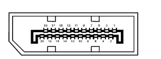
| Pin No. | Signal Name | Pin No. | Signal Name |
| 1 | ML_Lane 3 (n) | 11 | GND |
| 2 | GND | 12 | ML_Lane 0 (p) |
| 3 | ML_Lane 3 (p) | 13 | CONFIG1 |
| 4 | ML_Lane 2 (n) | 14 | CONFIG2 |
| 5 | GND | 15 | AUX_CH(p) |
| 6 | ML_Lane 2 (p) | 16 | GND |
| 7 | ML_Lane 1 (n) | 17 | AUX_CH(n) |
| 8 | GND | 18 | Hot Plug Detect |
| 9 | ML_Lane 1 (p) | 19 | Return DP_PWR |
| 10 | ML_Lane 0 (n) | 20 | DP_PWR |
Pin Color Display Signal Cable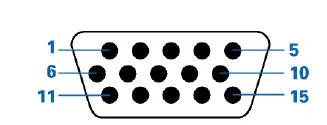
| Pin Number | 15-Pin Side of the Signal Cable | Pin Number | 15-Pin Side of the Signal Cable |
| 1 | Video-Red | 9 | +5V |
| 2 | Video-Green | 10 | Ground |
| 3 | Video-Blue | 11 | N.C. |
| 4 | N.C. | 12 | DDC-Serial data |
| 5 | Detect Cable | 13 | H-sync |
| 6 | GND-R | 14 | V-sync |
| 7 | GND-G | 15 | DDC-Serial clock |
| 8 | GND-B |
Plug and Play
Plug & Play DDC2B Feature
This monitor is equipped with VESA DDC2B capabilities according to the VESA DDC STANDARD. It allows the monitor to inform the host system of its identity and, depending on the level of DDC used, communicate additional information about its display capabilities.
The DDC2B is a bi-directional data channel based on the I2C protocol. The host can request EDID information over the DDC2B channel.


