CityGrows CG800 Series Wireless Switch
VERSION 1.2
10 JANUARY, 2020
Disclaimers and Copyright
Nothing contained in this publication is to be construed as granting any right, by implication or otherwise, for the manufacture, sale, or use in connection with any method, apparatus, or product covered by letters patent, or as insuring anyone against liability for infringement of letters patent. Efforts have been made to ensure the accuracy and reliability of the data contained in this publication; however, CityGrow Energy Systems Limited makes no representation, warranty, or guarantee in connection with this publication and hereby expressly disclaims any liability or responsibility for loss or damage resulting from its use or from the use of any product or methodology described herein; for any violation of any federal, state, or municipal regulation with which this publication may conflict; or for the infringement of any patent from the use of this publication. Nothing contained in this publication should be viewed as an endorsement by CityGrow Energy Systems Limited of any particular manufacturer’s products.
CAUTION
RISK OF ELECTRIC SHOCK DO NOT OPEN
CAUTION: TO REDUCE THE RISK OF ELECTRIC SHOCK, DO NOT REMOVE COVER (OR BACK) NO USER-SERVICEABLE PARTS INSIDE REFER SERVICING TO QUALIFIED SERVICE PERSONNEL
The lightning flash with arrowhead symbol within an equilateral triangle is intended to alert the user to the presence of uninsulated “dangerous voltage” within the product’s enclosure that may be of sufficient magnitude to constitute a risk of electric shock to persons.
The exclamation point within an equilateral triangle is intended to alert the user to the presence of important operating and maintenance (servicing) instructions in the literature accompanying the product.
IMPORTANT SAFETY INSTRUCTIONS
READ BEFORE OPERATING EQUIPMENT
This product was designed and manufactured to meet strict quality and safety standards.
There are, however, some installation and operation precautions which you should be particularly aware of.
- Read these instructions.
- Keep these instructions.
- Heed all warnings.
- Follow all instructions.
- Do not use this apparatus near water.
- Clean only with dry cloth.
- Do not block any ventilation openings. Install in accordance with the manufacturer’s instructions.
- Do not install near any heat sources such as radiators, heat registers, stoves, or other apparatus that produce heat.
- Do not defeat the safety purpose of the polarized or grounding-type plug. If the provided plug does not fit into your outlet, consult an electrician for replacement of the outlet.
- Protect the power cord from being walked on or pinched particularly at plugs, convenience receptacles, and the point where they exit from the apparatus.
- Only use attachments/accessories specified by the manufacturer.
- Use only with the cart, stand, tripod, bracket, or table specified by the manufacturer, or sold with the apparatus. When a cart is used, use caution when moving the cart/apparatus combination to avoid injury from tip-over.
- Unplug this apparatus during lightning storms.
- Refer all servicing to qualified service personnel. Servicing is required when the apparatus has been damaged in any way, such as power-supply cord or plug is damaged, liquid has been spilled or objects have fallen into the apparatus, the apparatus has been exposed to rain or moisture, does not operate normally, or has been dropped.
Introduction
Thank you for choosing CityGrow’s product. CG800 Series is highly-functional, user-friendly and installation-friendly. It is specially designed for wireless Home Automation control purpose.
Description
- ZigBee wireless remote control.
- Based on IEEE 802.15.4.
- 2.4GHz radio frequency.
- CG800S1/S2/S4/DM – lighting control.
- CG800S2/S4-CCP – Open/Close control for electric or motorized curtain and window blind.
- CG800xxH2 – 4 functions control.
- LED indicator for status indication.
- Plate button can perform two-way function.
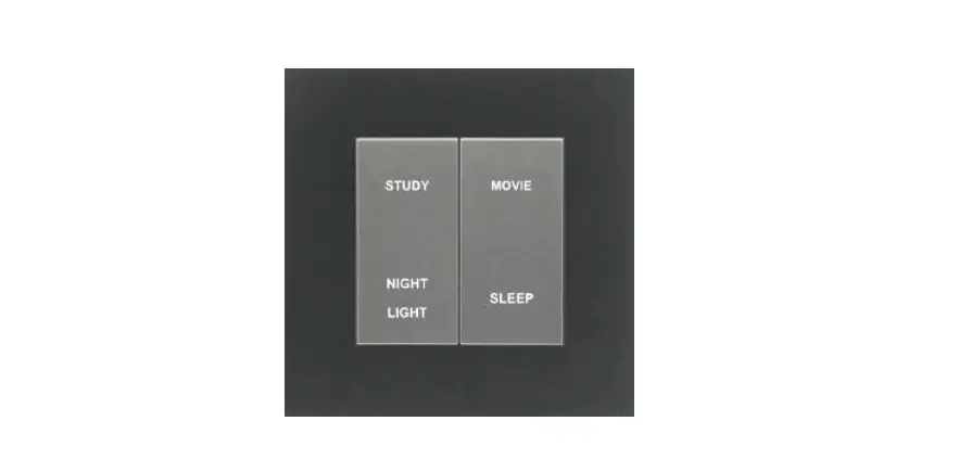
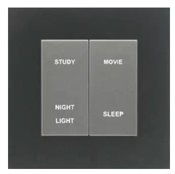
- Plate button can perform scene control function.
- Button graphics can be customized.
- With CG102BS-R Base Station, all devices support iOS/Android App control.
- Easy to install.
Understanding the product
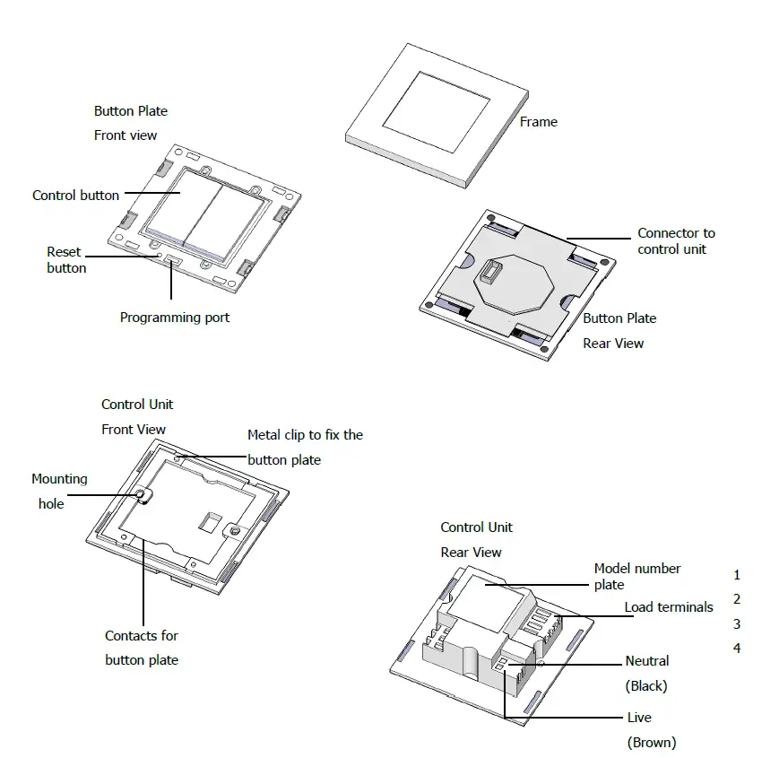
Load terminals to model number chart
| Load terminals | 1 | 2 | 3 | 4 |
| CG800S1 One Gang Switch | Load1 | NC | NC | NC |
| CG800S2 Two Gang Switch | Load 1 | Load 2 | NC | NC |
| CG800S4 Four Gang Switch | Load 1 | Load 2 | Load3 | Load 4 |
| CG800DM One Gang Dimmer | Load 1 | NC | NC | NC |
| CG800DM2 Two Gang Dimmer | Load 1 | Load 2 | NC | NC |
| CG800S2-CCP One Gang Curtain Control Switch | Motor 1 Backward | Motor 1 Forward | NC | NC |
| CG800S4-CCP Two Gang Curtain Control Switch | Motor 1 Forward | Motor 1 Backward | Motor 2 Forward | Motor 2 Backward |
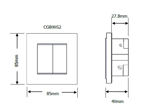
Dimensions
Wiring for CG800S1xx, CG800S2, CG800S4, CG800DMxx and CG800DM2xx
Before getting started
- WARNING! It must be installed by a qualified electrician in accordance to all applicable regulations and building codes. Improper wiring can result in personal injury or damage to control units or other equipment. Always turn off circuit breaker or remove main fuse from power line before doing any work. To avoid overheating and possible damage to equipment.
- WARNING! Do not operate when any lamps removed or burned out; replace any burned out lamps immediately; use only transformers that incorporate thermal protection or fused primary windings. This product is designed for residential and commercial use, for indoor use only.
- WARNING! Install in accordance to all national and local electrical codes.
- IMPORTANT! CityGrow® is not liable for any damage incurred with the misuse of the product. IMPORTANT! Pre-setup can only be done by a professional technician or manufacturer agent.
Reminder: The Neutral wire of load is closely connected to the Neutral point of CG800.
Situation 1: Live, Neutral and Load wires are ready at wall box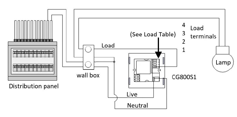
Situation 2: Live and Load wires are ready at wall box, Neutral wire is only ready at ceiling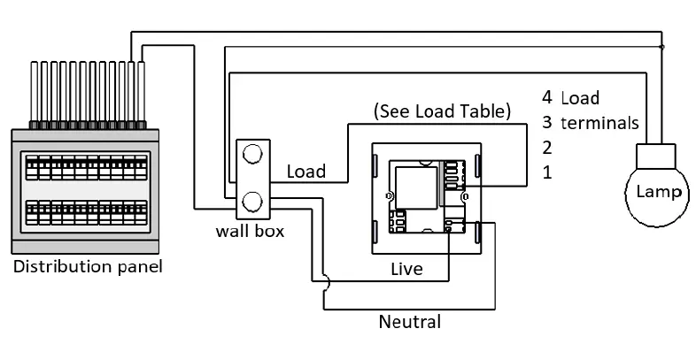
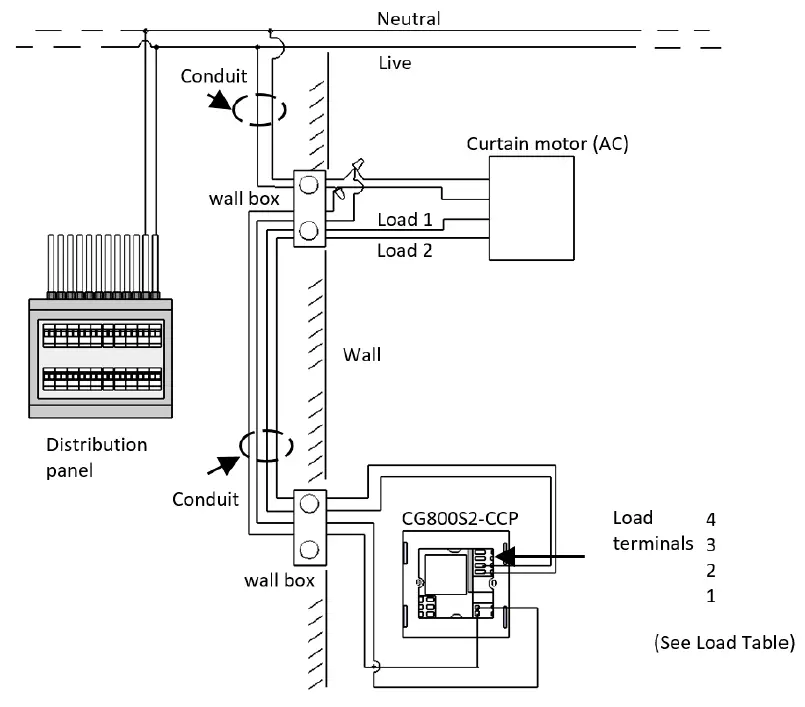
Wiring for CG800S2-CCP and CG800S4-CCP
Installation
Please follow the instructions to install the product.
STEP 1: IMPORTANT! Turn off main power at the main switch board.
STEP 2: Loosen the screws of the original wall switch. Remove the switch and disassemble the wiring.
STEP 3: Connect the main power cable to the Live and Neutral terminals and the load cable to the load terminals at the rear cabinet of the product.
STEP 4: Fasten the screws of all terminals and check that the wires are properly secured. Retrofit the switch into the standard switch box and mount it on the wall by fastening the two screws at the rear of the switch box.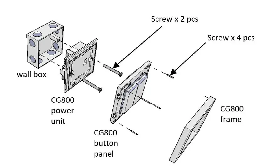
STEP 5: Press the ON/OFF button, to test whether the wiring has been connected correctly. If the ON/OFF Button does not function as expected, please check the wiring connection again.
Notes: Use Standard UK (BS4662) wall box for installation. It is recommended to embed the wall box with maximum depth fixed inside the wall for more sufficient installation space.
Operation instruction
CG800S1xx, CG800S2 and CG800S4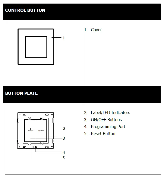
- Press ON/OFF Button once to toggle between ON and OFF.
- BRIGHT LED indicates that the Switch is ON.
- DIMMED LED indicates that the Switch is OFF.
CG800DMxx and CG800DM2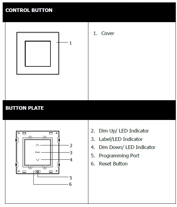
- Press the Dim Up/Dim Down button ONCE to Toggle between ON and OFF.
- LED FLASHING indicates that that the Button was pressed and dimming is in progress.
- When the LED stopped flashing, it indicates that the dimming is completed.
- Press and HOLD the Dim Up/Dim Down button to begin dimming.
- Release the button at the desired dimming level.
CG800S2-CCP and CG800S4-CCP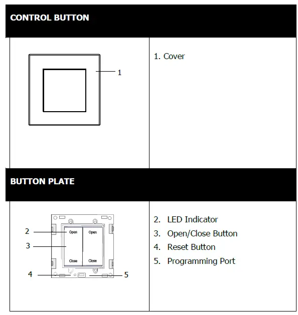
- Press the Open/Close Button once to control the electric curtain.
- Press the OPEN button to open the stopped electric curtain.
- Press the CLOSE button to close the stopped electric curtain.
- When the electric curtain is running, press ANY button to stop the electric curtain.
- Set the open and close travel distance for the curtain.
The function of the Learning Mode in the CG800S2-CCP and CG800S4-CCP is to program the duration of the curtain Opening/Closing time.
Please follow the instructions below to perform the Learning Mode function. 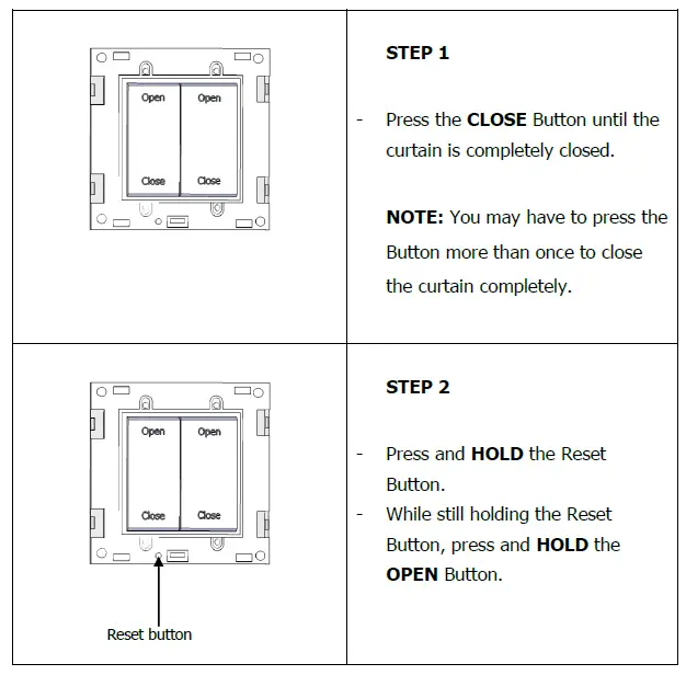
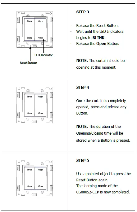
Notes: CG080S4-CCP is designed to control 2 curtain motors. Please complete the learning mode for both buttons of the CG800S4-CCP.
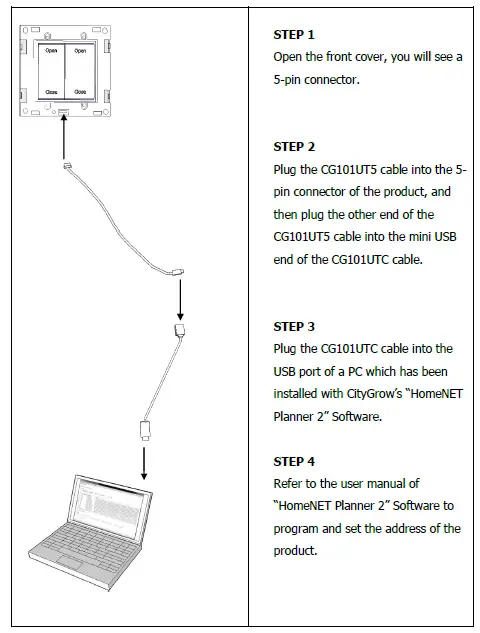
Adding the product to your Home Wireless ZigBee Network
Specification
| CG800S1 CG800S1H2 | CG800S2 | CG800S4 | CG800DM CG800DMH2 | CG800DM2 | CG800S2-CCP | CG800S4-CCP | |
| Description | One-Gang Switch | Two-Gang Switch | Four-Gang Switch | One-Gang Dimmer (Leading edge dimming) | Two-Gang Dimmer (Leading edge dimming) | One-Gang Curtain Control Switch | Two-Gang Curtain Control Switch |
| Operating voltage | AC220-240V, 50Hz | ||||||
| Maximum number of devices can be programmed in scene setting |
50 |
N/A | |||||
| Remarks: 1. When “Up” button has been programmed as dimming up function, the “Down” button cannot be programmed with scene function. 2. Each product can be programmed and control up to 50 devices. 3. The maximum load requirements for fluorescent, CFL and LED loads may vary depends on the specific fixture and/or bulb being used. 4. CG800 dimmers are compatible with leading edge dimmable lights. The dimming performance varies between devices, models and different manufacturers. Advance performance test is recommended before proceeding with the mass deployment. |
N/A | ||||||
| Minimum dimming level setting | N/A | Support | N/A | ||||
| Memory dim function | N/A | Support | N/A | ||||
| Two-way control function | Support | ||||||
| Control communications | ZigBee, IEEE 802.15.4 | ||||||
| Radio frequency | 2.4 GHz, 15 channels | ||||||
| Remote control distance (line of sight) | 100M | ||||||
| Operational temperature | 0°C to 40°C | ||||||
| Humidity | 5% to 95% non-condensing | ||||||
| Storage | -20°C to 70°C | ||||||
| Dimension L X W x D (mm) | 85x85x39 | ||||||
Specifications – Loads
| CG800S1 CG800S1H2 | CG800S2 | CG800S4 | CG800DM CG800DMH2 | CG800DM2 | CG800S2-CCP | CG800S4-CCP | |
| Description |
One-Gang Switch | Two-Gang Switch | Four-Gang Switch | One-Gang Dimmer (Leading edge dimming) | Two-Gang Dimmer (Leading edge dimming) | One-Gang Curtain Control Switch | Two-Gang Curtain Control Switch |
| Resistive load (Per Gang) 1. Incandescent 2. Halogen Electronic low voltage – ELV transformer |
2000W |
1000W |
500W |
600W |
300W |
N/A | |
| Inductive load (Per Gang) 1. Magnetic low voltage – MLV transformer. 2. Iron core / Inductive transformer |
2000VA |
1000VA |
500VA |
600VA |
300VA |
N/A | |
| Fluorescent (Per Gang) | 1400W | 700W | 350W | N/A | N/A | ||
| Compact fluorescent – CFL (Per Gang) | 400W
Max. 24 pcs CFL** | 400W
Max. 24 pcs CFL** | 200W
Max. 12 pcs CFL** | 400W Dimmable CFL Max. 20 pcs CFL** | 200W Dimmable CFL Max. 20 pcs CFL** |
N/A | |
| LED – GU10 (Per Gang) | 200W | 200W | 100W | 60W | 30W | N/A | |
| LED – MR16, MR11 (Per Gang) With electronic low voltage LED driver | 400W Max.24 pcs ELV LED driver* | 400W Max.24 pcs ELV LED driver* | 200W Max.12 pcs ELV LED driver* | 120W Max. 15 pcs ELV LED driver** | 60W Max. 15 pcs ELV LED driver** |
N/A | |
| LED strip (Per Gang) With electronic low voltage driver | 400W Max. 10 pcs ELV LED driver** | 400W Max. 10 pcs ELV LED driver** | 200W Max. 5 pcs ELV LED driver** |
N/A |
N/A | ||
| Exhaust fan (Per Gang) | 300VA | 300VA | 200VA | N/A | N/A | ||
| 3 wire type AC curtain motor | N/A | 300VA | 300VA | ||||
| Minimum load | N/A | 5W | 5W | N/A | |||
Remarks: The maximum load requirements for fluorescent, CFL and LED loads may vary depends on the specific fixture and /or bulb being used.


