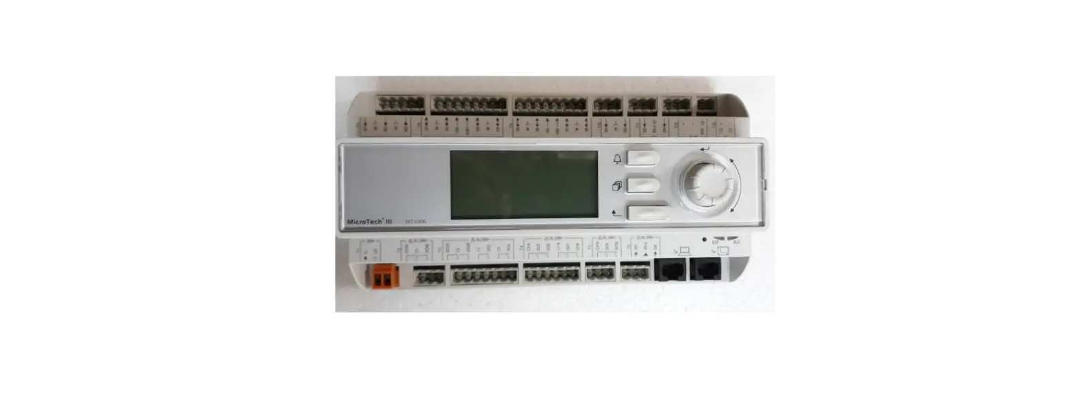
DAIKIN IM 1151-2 MicroTech III Smart Source Unit Controller

Installing A Motorized Valve For Use With MicroTech® III Smart Source Unit Controller
Introduction
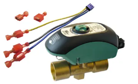
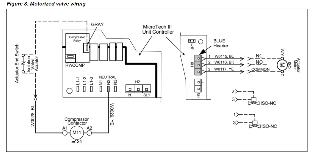
The motorized valve kit is available as a factory-installed and wired option or may be ordered as a field-installed accessory. Wired as shown in Figure 8, the motorized valve will open on a call for compressor operation. The motorized isolation valve actuator (ISO) has both a 24V power connection and a 24V end switch connection.
Figure 1: Two-way motorized valve kit
 Installation Considerations
 Installation Considerations
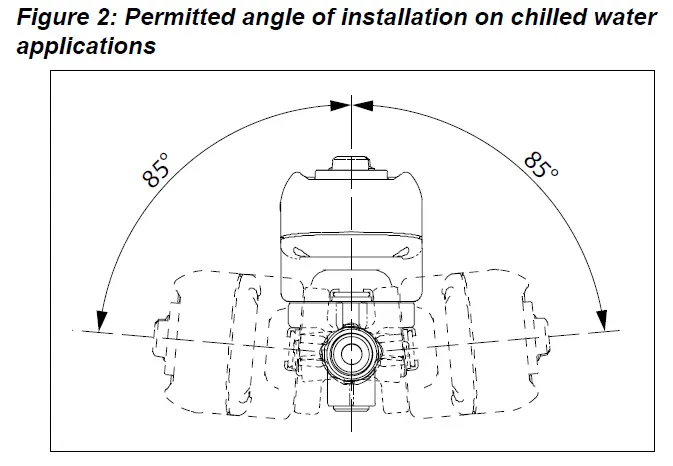
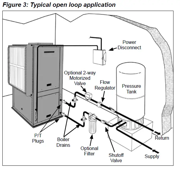
Note the placement of the water control valve in Figure 3.
- On hot water applications, the valve body may be installed in any orientation. On chilled water install-lations, do not install with the actuator beyond 85°from the top-most installation (see Figure
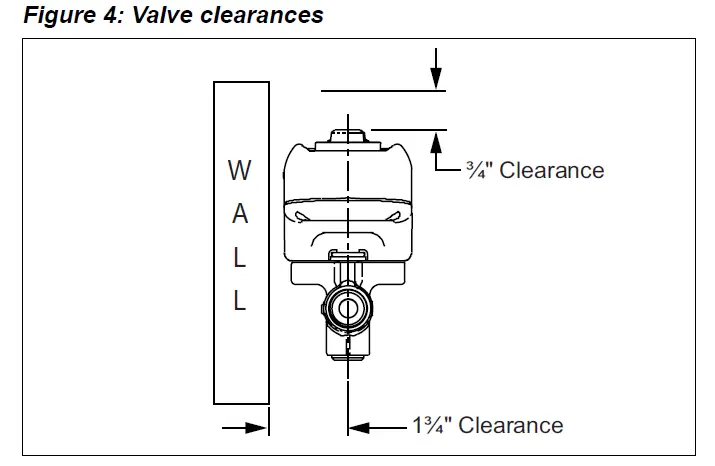
- Before mounting the body, refer to Figure 4 for clearance requirements.
CAUTION
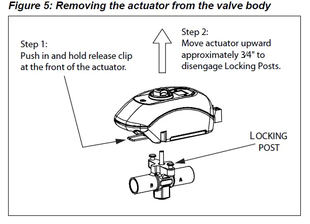
The actuator must be removed from the valve body before soldering (see Figure 5). Ball valve must be in the fully open position before soldering. Valve shipped in the closed position.
Actuator Removal
To remove the valve actuator:
- Push in and hold the release clip at the front of the actuator
- Lift actuator upward approximately 3⁄4″ (Figure 5).
Figure 5: Removing the actuator from the valve body
About Soldering
- Use of solder with a melting point below 600°F is recommended. Do not overheat! Make sure the ball valve is in the FULL OPEN position during soldering. Direct flame tip away from the center of the valve. Cool valve quickly with a wet cloth.
- Solder build-up on the ball valve may prevent proper opening and closing of the valve. Actuate the actuator once or twice and make sure the valve rotates fully.
- The valve body can be submerged for leak testing before the actuator is attached
To Re-Assemble The Actuator To The Valve Body:
- Position the actuator such that the “D” shaped valve stem aligns properly with the “D” shaped actuator drive cavity.
Note: The “D” shaped stem design allows for correct insertion every time. - Slide the valve stem into the actuator cavity, push in and hold the release clip until the actuator slips over the valve locking posts (see Figure 5).
- Once the actuator is flush to the valve body, let go of the release clip. Using very little force, try to lift the actuator off of the valve body without using the release clip. Both locking posts should be firmly attached to the actuator. If the actuator slides up the stem, repeat the assembly process.
Changing The Actuator Orientation
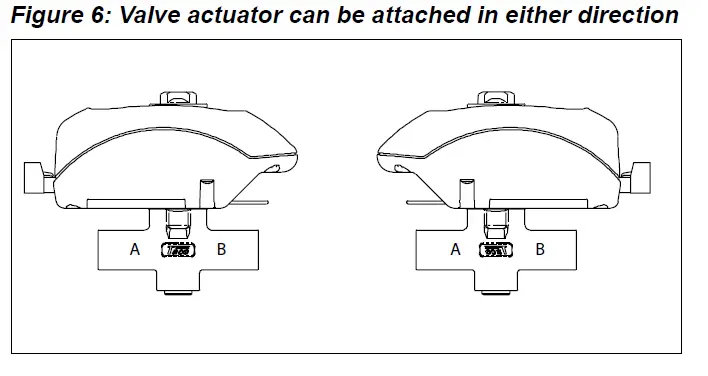
The actuator may be attached to the valve body in either direction, see Figure 6.
Figure 6: Valve actuator can be attached in either direction
To reverse the actuator orientation on the valve body, see the “Actuator Removal” instructions and refer to Figure 5, with the following exception.
- Instead of lifting the actuator the full 3⁄4″, move it just high enough to clear the locking posts, rotate the actuator 180° and reinstall it on the locking post by following the previous instructions, “To Re-Assemble The Actuator To The Valve Body:”
Wiring The Motorized Isolation Valve To The MicroTech III SmartSource Unit Controller
WARNING
Wiring connections must be made in accordance with all applicable electrical codes.
CAUTION
To prevent electrical shock, disconnect electric power to the system at the main fuse or circuit breaker box until installation is complete. When a service switch is installed, more than one disconnect switch may be required to de-energize this device for servicing,
Procedure
- Install the supplied wire harness 3-pin receptacle into the blue header terminal (H8) on the MicroTech III SmartSource control board, (Figure 7).
- Run wires between the Actuator Motor ISO and the supplied wire harness end connectors, (Figure 7). Notes: 1. Connect the N.O or N.C. wire to the actuator (W/Y) as shown on the schematic. The end switch should be wired in series with the 24V compressor signal wire, when applicable.
- Only wire end switch when M11 is in unit and is controlled with 24 volts AC.
- Use the wire end connectors provided with the kit for field wiring the actuator end switch (Figure 8).
- Connect the end switch wires as shown in the sche- matic, Figure 8. The end switch will close when the valve is fully open, (unit sizes 015-072).
Figure 7: Plug 3-pin receptacle into terminal H8
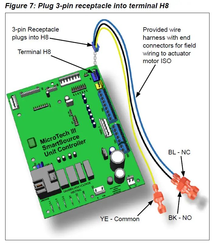
Figure 8: Motorized valve wiring
MOTORIZED VALVE MODES OF OPERATION & TROUBLESHOOTING
- Upon initial field installation the capacitor requires a full charge, up to 35 seconds, before the valve starts to turn. Charging time will vary (typically less) during normal operation.
- When the capacitor is charging the green LED light will FLASH.
- Once the capacitor is charged, the green LED will stop flashing but remain ON. At this point the valve’s actuator will rotate the ball valve. The green LED will remain ON as long as the thermostat is calling (the unit is powered).
- Once the thermostat is satisfied the green LED will turn OFF and the valve will rotate 90° into its normal position or non-powered position. For example: If the actuator is an NC (normally closed) version, the actuator would open the valve when the thermostat calls. Once the thermostat is satisfied the actuator would then rotate the valve 90° to its normally closed position.
Table 5: Flow coefficients and maximum close-off pressure
| Valve Size | CV (KV)/Ft. of Pipe Equivalent1 | Close-Off PSI (kPa) |
| 1/2″ | 4.9 (4.3)/9.5 | 0-125 psi (0-862 kPa) |
| 3/4″ | 10.3 (8.9)/8.4 | |
| 1″ | 8.9 (7.7)/47.4 |
Note: 1 At 4′ per second (maximum recommended residential flow rate).
Table 6: Multi-status LED and troubleshooting
| LED Status | Indicates | Possible Cause | Possible Solution |
| Not Illuminated | Power off | • No call • No power | • Verify there is a call. • Check for voltage at the actuator |
| Steady blink (once per second) | Charging | ||
| Solid | Power on | ||
| Slow blink (once every 5 seconds) |
Excessive charging time | • Not enough VA • Too many valves per transformer | • Reset the actuator (see note). • Use a larger VA transformer or add an additional transformer. • Reduce the number of valves. • Use a different thermostat. |
| Double blink (twice every 5 seconds) | Excessive opening time | • Obstruction in valve • Buildup of contamination in valve | • Reset the actuator (see note). • Remove obstruction. • Clean the valve and/or system. |
Warranty
All Daikin equipment is sold pursuant to its standard terms and conditions of sale, including Limited Product Warranty. Consult your local Daikin Applied representative for warranty details. Refer to Form 933-430285Y. To find your local Daikin Applied representative, go to www.DaikinApplied.com
Aftermarket Services
To find your local parts office, visit www.DaikinApplied.com or call 800-37PARTS (800-377-2787). To find your local service office, visit www.DaikinApplied.com or call 800-432-1342.
This document contains the most current product information as of this printing. For the most up-to-date product information, please go to www.DaikinApplied.com
IM 1151-2 ©2021 Daikin Applied (10/21) | (800) 432–1342 | www.DaikinApplied.com


