![]()
![]()
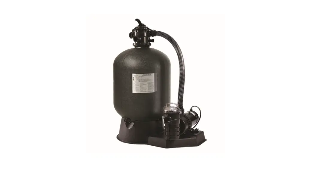
SAND DOLLAR® AND CRISTAL-FLO™ II TOP MOUNT SAND FILTER
INSTALLATION AND USER’S GUIDE
IMPORTANT SAFETY INSTRUCTIONS
READ AND FOLLOW ALL INSTRUCTIONS
SAVE THESE INSTRUCTIONS
TECHNICAL SUPPORT
If you have questions about ordering Pentair Aquatic Systems replacement parts, and pool products, please contact:
Technical Support, USA
Sanford, North Carolina (8 A.M. to 4:30 P.M. ET)
Moorpark, California (8 A.M. to 4:30 P.M. PT)
Phone: (800) 831-7133
Fax: (800) 284-4151
Web site
Visit www.pentairpool.com or www.staritepool.com for information about Pentair products.
IMPORTANT WARNING AND SAFETY INSTRUCTIONS
![]() SERIOUS BODILY INJURY OR DEATH CAN RESULT IF THIS SAND FILTER IS NOT INSTALLED AND USED CORRECTLY.
SERIOUS BODILY INJURY OR DEATH CAN RESULT IF THIS SAND FILTER IS NOT INSTALLED AND USED CORRECTLY.![]() INSTALLERS, POOL OPERATORS, AND POOL OWNERS MUST READ THESE WARNINGS AND ALL INSTRUCTIONS BEFORE USING
INSTALLERS, POOL OPERATORS, AND POOL OWNERS MUST READ THESE WARNINGS AND ALL INSTRUCTIONS BEFORE USING
THIS SAND FILTER.
This sand filter is intended for use in swimming pool applications.
Most states and local codes regulate the construction, installation, and operation of public pools and spas, and the construction of residential pools and spas. It is important to comply with these codes, many of which directly regulate the installation and use of this product. Consult your local building and health codes for more information.
![]() IMPORTANT NOTICE – Attention Installer: This Installation and User’s Guide (“Guide”) contains important information about the installation, operation, and safe use of this sand filter. This Guide should be given to the owner and/or operator of this equipment.
IMPORTANT NOTICE – Attention Installer: This Installation and User’s Guide (“Guide”) contains important information about the installation, operation, and safe use of this sand filter. This Guide should be given to the owner and/or operator of this equipment.
![]() Before installing this product, read and follow all warning notices and instructions in this Guide. Failure to follow warnings and instructions can result in severe injury, death, or property damage. Call (800) 831-7133 for additional free copies of these instructions. Please refer to www.pentair.com for more information related to this product.
Before installing this product, read and follow all warning notices and instructions in this Guide. Failure to follow warnings and instructions can result in severe injury, death, or property damage. Call (800) 831-7133 for additional free copies of these instructions. Please refer to www.pentair.com for more information related to this product.
![]()
 Water temperature in excess of 100° F (37.7° C) may be hazardous to your health. Prolonged immersion in hot water may induce hyperthermia. Hyperthermia occurs when the internal temperature of the body reaches a level several degrees above normal body temperature of 98.6° F. (37° C.). Effects of hyperthermia include (1) Unawareness of impending danger. (2) Failure to perceive heat. (3) Failure to recognize the need to leave the spa. (4) Physical inability to exit the spa. (5) Fetal damage in pregnant women. (6) Unconsciousness resulting in danger of drowning. The use of alcohol, drugs, or medication can greatly increase the risk of fatal hyperthermia in hot tubs and spas.
![]() Do not permit children to use or operate this sand filter.
Do not permit children to use or operate this sand filter.![]() When setting up pool water turnovers or flow rates the operator must consider local codes governing turnover as well as disinfectant feed ratios.
When setting up pool water turnovers or flow rates the operator must consider local codes governing turnover as well as disinfectant feed ratios.![]() DO NOT increase pump size; this will increase the flow rate through the system and may exceed the maximum flow rate stated on the drain cover.
DO NOT increase pump size; this will increase the flow rate through the system and may exceed the maximum flow rate stated on the drain cover.![]() For filters intended for use other than single-family dwellings, a clearly labeled emergency switch shall be provided as part of the installation. The switch shall be readily accessible to the occupants and shall be installed at least 5 feet (1.52 m) away, adjacent to, and within sight of, the filter.
For filters intended for use other than single-family dwellings, a clearly labeled emergency switch shall be provided as part of the installation. The switch shall be readily accessible to the occupants and shall be installed at least 5 feet (1.52 m) away, adjacent to, and within sight of, the filter.
IMPORTANT WARNING AND SAFETY INSTRUCTIONS
High Pressure from the Sand Filter can cause severe injury or major property damage due to tank separation.
Release all pressure and read instructions before working on the sand filter.
If the filter clamp is adjusted under pressure, the tank can separate, causing serious injury or major property damage.
BEFORE WORKING ON FILTER!
(1) Stop the pump.
(2) Open-air release valve.
(3) Release all pressure from the system.
![]()

RISK OF ELECTRICAL SHOCK OR ELECTROCUTION:
PUMPS REQUIRE HIGH VOLTAGE WHICH CAN SHOCK, BURN, OR CAUSE DEATH.
BEFORE WORKING ON THE PUMP!
Always disconnect power to the pool pump at the circuit breaker from the pump before servicing the pump. Failure to do so could result in death or serious injury to service personnel, pool users, or others due to electric shock.
![]() A pool or spa pump must be installed by a qualified pool and spa service professional in accordance with the National Electrical Code and all applicable local codes and ordinances. Improper installation may create an electrical hazard that could result in death or serious injury to pool users, installers, or others due to electrical shock, and may also cause damage to property.
A pool or spa pump must be installed by a qualified pool and spa service professional in accordance with the National Electrical Code and all applicable local codes and ordinances. Improper installation may create an electrical hazard that could result in death or serious injury to pool users, installers, or others due to electrical shock, and may also cause damage to property.
![]() Pumps are not a substitute for properly installed and secured pool drain covers. An ANSI/ASME A112.19.8 approved anti-entrapment drain cover must be used for each drain. Pools and spas should utilize a minimum of two drains per pump. If a drain cover becomes loose, broken, or is missing, close the pool or spa immediately and shut off the pump until an approved anti-entrapment drain cover is properly installed with the manufacturer’s supplied screws.
Pumps are not a substitute for properly installed and secured pool drain covers. An ANSI/ASME A112.19.8 approved anti-entrapment drain cover must be used for each drain. Pools and spas should utilize a minimum of two drains per pump. If a drain cover becomes loose, broken, or is missing, close the pool or spa immediately and shut off the pump until an approved anti-entrapment drain cover is properly installed with the manufacturer’s supplied screws.
For information about the Virginia Graeme Baker Pool and Spa Safety Act, contact the Consumer Product Safety Commission at (301) 504-7908 or visit www.cpsc.gov.
Important Note: Always turn off all power to the pool pump before installing the cover or working on any suction outlet.
FILTER OVERVIEW
Your high rate sand filter is designed to produce clear, sparkling water and operate for years with a minimum of maintenance when installed, operated, and maintained in accordance with these instructions. Your filter uses special filter sand to remove dirt particles from the water. Dirt is collected in the filter by the sand bed as water flows through the filter. Water enters the filter through the valve on top of the filter and is distributed evenly downward across the sand bed. The dirt is removed by the sand and the clean water flows through the piping (laterals) at the bottom of the filter, up through the standpipe, back to the valve on top of the filter, where the clean water is returned to the pool through the piping or hoses.
This filter operates under high pressure. When any part of the circulating system (e.g., clamp, pump, filter, valves, etc.) is serviced, air can enter the system and become pressurized. Pressurized air can cause the lid or control valve to separate which may result in serious injury, death, or property damage. To avoid this potential hazard, follow these instructions.
- Before repositioning valves and before beginning the assembly, disassembly, or adjustment of the clamp or any other service of the circulating system:
(a) Turn the pump off and shut off any automatic controls to ensure the system is not inadvertently started during the servicing;
(b) Open manual air relief valve;
(c) Wait until all pressure is relieved, pressure gauge must read zero (0). - Whenever installing the filter clamp, follow the filter valve and clamp installation instructions exactly.
- Once service on the circulating system is complete, follow system restart instructions exactly.
- Maintain circulation system properly. Replace worn or damaged parts immediately (e.g., clamp, pressure gauge, relief valve, o-rings, etc.).
- Be sure that the filter is properly mounted and positioned according to the instructions provided.
After a period of time, dirt will accumulate in the filter causing a resistance to the flow of water through the filter. This resistance results in a diminished flow of water and a rise in the pressure of the filter. Eventually, the filter sand will have removed so much dirt, and the filter pressure has risen to such a point that it will be necessary to clean (backwash) your filter.
By setting the valve on top of the filter to the “Backwash” position, the flow of water is automatically reversed through the filter so that the flow of water is directed to the bottom of the filter, up through the sand bed, flushing the dirt and debris out through the waste line. Once the backwash procedure is complete, the valve is manually returned to its “Filter” position to resume normal filtration. The filter’s function is to remove suspended matter from the water. It does not sanitize the water. For sparkling clear water, the water must be sanitized as well as balanced. Pool chemistry is a specialized area, and you should consult your local pool service specialist for specific details. In general, proper pool sanitation requires a free chlorine level of 1 to 2 PPM and a pH range of 7.2 to 7.6. Your filtration system should be designed to meet your local health codes. As a minimum, you must be sure that your system will turn over the total volume of water in your pool at least twice in a twenty-four-hour period.
![]() Failure to operate your filter system or inadequate filtration can cause poor water clarity obstructing visibility in your pool. Poor water clarity may obscure objects in the water which while swimming and diving could cause serious personal injury or death. Never swim in a pool with poor water clarity.
Failure to operate your filter system or inadequate filtration can cause poor water clarity obstructing visibility in your pool. Poor water clarity may obscure objects in the water which while swimming and diving could cause serious personal injury or death. Never swim in a pool with poor water clarity.
INSTALLATION
- Read and understand all instructions before attempting to install, operate or maintain your pump and sand filter system.
- Provide space and lighting for routine maintenance access. Locate the system close to the pool. Install electrical controls (e.g., on/off switches, timers, control systems, etc.) at least five (5) feet from the filter. This will allow you enough room to stand clear of the filter during system start-up.
- Remove all individual components from the carton and inspect for any visible damage. If cartons or parts are damaged contact the seller or freight company.
 Blockage of suction fittings can cause serious or fatal injury due to drowning. To reduce the risk of injury, do not permit children to use this product. Never work on the pump while it is running or power is still connected. High voltage can cause serious or fatal injury. A suitable ground fault interrupter (GFCI) should always be installed at the power supply source of this unit. Be sure to ground the motor before connecting to the electrical AC power supply. Failure to ground the motor can cause a serious or fatal electrical shock hazard. DO NOT ground to a gas supply pipeline.
 - The filter is ready to be moved into its final position. The system must be placed on a level solid earth. When the filter is filled with sand and water it can weigh several hundred pounds.
- Be certain to install the precise amount of filter sand listed on your filter nameplate. You must use only No. 20 standard silica sand having a uniformity coefficient of 1.75 or less. No. 20 silica sand has a particle size of .018-.022 inches (.45 to .55 mm). Before pouring the sand into the filter, look inside and check the lower underdrain for broken or loose laterals (or fingers), which may have been accidentally damaged by rough handling during shipment. Replace any broken parts if necessary.
- Install the sand guide at the top of the filter and fill the tank about half full of water. Pour the sand into the top of the filter at a slow rate so that the weight of the sand does not damage the laterals. After the required amount of sand has been installed, remove and discard the sand guide. Wash away all sand around the opening at the top of the tank.
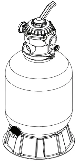
- Be sure the top of the filter is free of any sand or debris and valve o-ring is in place on the valve body. Install valve so that the port locations are in the desired final position. Valve ports are labeled with the location of where they should be connected i.e. pump port must go to pump discharge, the waste port must go to the waste line, and the return port must go to the pool return.
- Ensure that the valve is firmly pushed into the top of the tank and that the flange of the tank and the flange of the valve are contacting each other. See Figure 1.

- The plastic clamp can now be installed. Place the clamp half over the valve flange and the tank flange as shown in Figure 1. Insert the clamp screws and nuts into the clamp making sure that the nuts are located in the special hexagonal retainer slots on the clamps. See Figure 2.
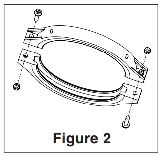
- Tighten clamp screws firmly and visually check the valve tank and clamp assembly to ensure that the joint is correctly assembled.
 High Pressure:
Improper tank valve assembly could cause the valve to separate and cause serious injury and/or major property damage. - The filter unit has a maximum operating pressure listed on the filter nameplate. DO NOT OPERATE this unit above the maximum operating pressure of the valve or the filter. Never connect the filter and valve unit to a pump that can generate a pressure that exceeds the operating pressure of the filter or valve.
- Use sealant on all tapered male connections of pipes and fittings. Use only sealant compounds suited for plastic pipes. Support pipe to prevent strains on filter, pump, or valve. DO NOT USE PETROLEUM-BASED PRODUCTS. NOTICE: All valve internal threads are tapered except the air bleeder connection. Do not over-tighten tapered thread connections.
- Install pressure gauge in 1/4” NPT port directly across from the pump port of the valve.
- Never store pool chemicals within ten (10) feet of your pool filter, pump, or valve. Pool chemicals should always be stored in a cool, dry, well-ventilated area. Chemical fumes and/or spills can cause serious corrosion to the filter and pump structural components. Structurally weakened components can cause filter, pump, or valve attachments to separate and could cause serious bodily injury or property damage. The system’s centrifugal pump operates with electrical voltage and can generate both vacuum and pressure in the water system. When properly wired and plumbed, this pump will operate in a safe manner. High voltage can cause serious or fatal injury. Always install a suitable GFCI at the power source of this unit as an added safety precaution. Article 681-31 of the NEC requires that a GFCI be used if this pump is used with a storable pool.
- Avoid over-tightening the pipe threads when connecting fittings to the pump or valve. The proper procedure is to apply a pipe sealant to the thread and then install hand tight plus one turn. DO NOT OVERTIGHTEN.

 High Pressure:
OPERATION AND MAINTENANCE
Initial Start-Up
- Be sure the correct amount of silica filter sand is in the tank and that all connections have been made and are secure.
- Verify that the backwash is open so that water is free to flow from the pool and out the backwash line. Set the control valve to the “Backwash” position.

This filter operates under pressure. With the valve clamped properly and operated without air in the system, this filter will operate in a safe manner. Air entering the filter and the valve not clamped correctly can cause the valve to separate, which could cause serious personal injury and/or property damage. Always turn the pump off before changing valve positions. Changing valve positions while the pump is running can damage the control valve, which may cause serious injury or property damage. - Check the valve clamp on the filter for proper installation. For valve clamp installation instructions, see “Installation” on page 2.
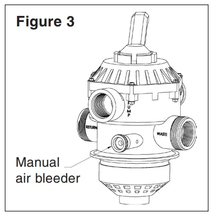
- Open the manual air bleeder. (See Figure 3 for air bleeder location). STAND CLEAR OF THE FILTER. Prime and start the pump according to the pump instructions allowing the filter tank to fill with water. Close the air bleeder on the filter when a steady stream of water emerges.
- Once the water flow is steady out the waste line, run the pump for at least two minutes.
This initial backwashing of the filter is recommended to remove any impurities of fine sand particles in the silica sand media. - Turn the pump off and set the valve to “Rinse” position. Ensure that all pool suction and return lines are open so that the water is free to flow from the pool to waste. STAND CLEAR OF FILTER and start the pump.
- Run the pump for at least two minutes.
- Turn the pump off and set the valve to the “Filter” position. Be sure that all pool suction and return lines are open so that water is free to flow from and to the pool.
- Open the manual air bleeder on the filter. STAND CLEAR OF FILTER and start the pump.
- Close the air bleeder on the filter when a steady stream of water emerges.
- The filter has now started its filtering cycle. Verify that water is returning to the pool and take note of the operating pressure. The original starting pressure is ___________ psi with the filter clean.
- Check the system for water leaks. If a leak is found, shut the pump off before correcting the leak.
- As the filter removes dirt and impurities from the pool water, the accumulation will cause the filter pressure to rise and flow to diminish. When the pressure gauge reading is 10 psi higher than the clean filter reading noted above, it is time to backwash the filter.
General Maintenance
Proper care and maintenance of the pump and sand filter system will add many years of enjoyment to the pool. Follow these suggestions for a long trouble-free operation.
- To clean the exterior of the pump and sand filter system of dust and dirt, wash with mild detergent and water and then hose off.
Do not use solvents. - If internal filter maintenance is required and may be removed by removing the entire drain spigot from the bottom of the filter and flushing it with a garden hose.
- The filter is a pressure vessel and should never be serviced while under pressure. Always relieve tank pressure and open-air bleeder on the filter before attempting to service the filter.
- When restarting the filter always open the manual air bleeder on the filter and STAND CLEAR OF FILTER.
- The strainer basket in the pump should be inspected and cleaned twice each week. Remove the clear lid and the basket, and clean debris from the basket. Inspect the lid o-ring; if damaged, replace.
The pump seal requires no lubrication. The pump motor should only be serviced by a motor service center.
Cleaning
- The filter on a new pool should be backwashed and cleaned after the first 48 hours of operation to clean out construction debris. There are three different ways to identify when the filter needs backwashing:
a) The most accurate indicator on pool systems with a flow meter is to backwash when the flow decreases 30% from the original (clean filter) flow. For example, if the original flow was 60 GPM, the filter should be backwashed when the flow is reduced by about 20 GPM (or 30%) to 40 GPM.
b) A more subjective and less accurate indicator is to observe the amount of water flowing from the flow directionals located in the wall of the pool. The filter should be backwashed once it is detected that the flow has been reduced.
c) The most commonly used, but the least accurate indicator is to backwash when the filter gauge reading increases 10 psi over the initial (clean filter) reading. - It is important not to backwash the filter solely on a timed basis such as every three (3) days. It is also important to note that backwashing too frequently actually causes poor filtration. Factors like weather conditions, heavy rains, dust or pollen, and water temperatures all affect the frequency of backwashing. As you use your pool, you will become aware of these influences.
Filter and Control Valve Functions
FILTER: From pump, through valve, downward through filter sand bed, up through center pipe to valve return port, and back to the pool for normal filter action and vacuuming pool through filter.
BACKWASH: From pump, through valve, down through center pipe, up through filter sand to valve, and out waste port. This position is used for cleaning filter by reversing flow.
RINSE: From pump, through valve, downward through filter sand, up through center pipe to valve and out waste port. This position is used for start up cleaning and resettling filter bed after backwashing.
WASTE: From pump, through valve, bypasses filter and goes to waste port. This position is for vacuuming directly to waste, lowering pool level, or draining pool.
CLOSED: NO FLOW IN THIS POSITION – DO NOT USE THIS
SETTING WHILE PUMP IS OPERATING.
RECIRCULATE: From pump, through valve, bypasses filter and goes to return port and back to pool. This position is for circulating water without going through filter.
WINTERIZING: Valve position for a winterized filter, see page 10.
Filter Backwash Procedure
![]() Failure to operate your filter system or inadequate filtration can cause poor water clarity obstructing visibility in your pool. Poor water clarity may obscure objects in the water which while swimming and diving could cause serious injury or death. Never swim in a pool with poor water clarity.
Failure to operate your filter system or inadequate filtration can cause poor water clarity obstructing visibility in your pool. Poor water clarity may obscure objects in the water which while swimming and diving could cause serious injury or death. Never swim in a pool with poor water clarity.![]() To prevent equipment damage and possible injury, always turn the pump off before changing the valve position.
To prevent equipment damage and possible injury, always turn the pump off before changing the valve position.
- Stop pump.
- Ensure that the suction and backwash lines are open so that water is free to come from the pool and flow out the backwash line. Set control valve to “Backwash” position.
- STAND CLEAR OF FILTER and start the pump.
- Backwash filter for approximately three (3) minutes or until backwash water is clean.
- Stop the pump and set the valve to the “Rinse” position.
- STAND CLEAR OF FILTER and start pump..
- Rinse the filter for approximately 30 seconds.
- Stop the pump and set the valve to the “Filter” position.
- Ensure the pool return line is open so that water may flow freely from the filter back to the pool.
- Open the manual air bleeder on the filter. STAND CLEAR OF FILTER and start the pump.
- Close manual air bleeder on the filter when a steady stream of water emerges from the bleeder.
- The filter has now started its filtering cycle. Verify the water is returning to the pool and take note of the filter pressure.
- The filter pressure in Step 12 above should not exceed the pressure originally observed on the filter when it was initially started. If after backwashing, the pressure is 4 to 6 psi above the start condition it will be necessary to chemically clean the sand bed.
Chemical Cleaning
- It is recommended that a specialty filter cleaning solution be used. These cleaners will remove oils, scale, and rust from the sand bed in one cleaning operation.
- Mix the solution following the manufacturer’s instructions on the label.
- Backwash the filter with the valve as described above.
- If the filter is below pool level, switch the pump off and close the appropriate valves to prevent draining the pool.
- Switch off-pump, open filter drain, and allow the filter to empty. Place valve in “Backwash” position.
- After the filter has drained, close the filter drain and remove the pump strainer pot lid.
- Be sure the backwash lines are open.
- Switch the pump on and slowly pour the cleaning solution into the pump strainer with the pump running. If the filter is below the pool, open the shut-off valve slightly to allow the pump to run.
- Continue adding solution until the sand bed is saturated with cleaning solution.
- Switch off the pump and leave the filter in the “Backwash” position. Allow the filter to stand overnight (12 hours).
- Replace the pump lid and follow the backwash procedure as described above.
- Do not allow cleaning solutions to get into the pool.
Winterizing the System
![]() Allowing water to freeze in the system will damage the system and cause potential water damage/flooding and potential property damage.
Allowing water to freeze in the system will damage the system and cause potential water damage/flooding and potential property damage.
- In areas that have freezing winter temperatures, the pool equipment must be winterized to protect it from damage.
- Backwash the filter. Switch off the pump and set the control valve to the “Winterize” position.
- Remove the drain port cap at the bottom of the filter.
IMPORTANT NOTE: Remove drain port cap only for draining water from the filter. Removing the entire fitting will allow sand to drain also. The filter will drain slowly. Leave the drain port cap off and store it during the time the system is shut down. The Multiport Valve should be left in the “Winterize” position during the shutdown season so that the rubber seal of the valve diverter has no pressure on it. Failure to do so can damage the valve diverter seal which can cause property damage from leaking water.
 - Drain all appropriate system piping.
- It is recommended that the pump and filter be covered with a tarpaulin or plastic sheet to inhibit deterioration from the weather. DO NOT wrap the pump motor with plastic.
- In installations where the pump cannot be drained a 40% Propylene Glycol 60% water solution will protect to -50° F (-45.5° C)
Note: Do not use anti-freeze solutions except Propylene Glycol; as other anti-freeze are highly toxic and will damage the pump.
TROUBLESHOOTING
Problem | Cause | Action |
| Pool water not sufficiently clean. | 1. Pool chemistry not adequate to inhibit algae growth. 2. Too frequent a backwash cycle. 3. Improper amount or wrong sand size. 4.Inadequate turnover rate. | Maintain pool chemistry or consult service technician. Allow pressure to build to 10PSI above clean filter condition before backwashing. Check sand bed depth and sand size or consult pool service technician. Run system for longer time or consult dealer or pool service technician. |
| Higher filter pressure. | 1. Insufficient backwashing. 2. Sand bed plugging with mineral deposits. 3. Partially closed valve or restriction. | Backwash until effluent runs clear. Chemically clean filter. Open valve or remove obstruction in return line. |
| Short filter cycles. | 1. Improper backwashing. 2. Pool chemistry not adequate to inhabit algae growth. 3. Plugged sand bed. 4. Flow rate too high | Backwash until effluent runs clear. Maintain pool chemistry or consult pool service technician. Manually remove top 1″ surface of sand bed and chemically clean as required. Restrict flow to capacity of filter. |
| Return flow to pool diminished, low filter pressure. | 1. Obstruction in the pump hair and lint pot. 2. Obstruction in pump. 3. Obstruction in suction line to pump. | Clean basket in strainer. Disassemble and clean pump. Clean skimmer basket. Remove obstruction in lines. Open valves in suction line. |
| Sand returning to pool. | 1. Broken underdrain lateral. 2. Backwash rate too high. | Replace broken or damaged laterals. Reduce backwash flow rate. |
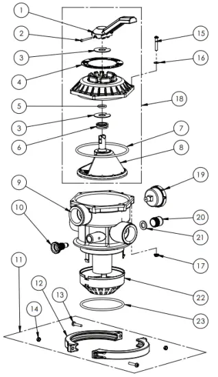
REPLACEMENT PARTS
Filter Replacement Parts

Item # | Description | Sand Dollar Part # | Cristal-Flo Part # |
| 1 | Valve, 1.5” (See page 14 for Valve Breakdown) | 262506 | |
| Valve, 2” (See page 15 for valve breakdown) | 263085 | ||
| 2 | O-Ring, Valve Body | 272541 | |
| 3 | Clamp Assembly | 152165 | |
| 4 | Piping Asy. – SD/CFII 35 | 152229 | |
| Piping Asy. – SD/CFII 40 | 152228 | ||
| Piping Asy. – SD/CFII 60 | 152227 | ||
| Piping Asy. – SD/CFII 70 | 152000 | ||
| Piping Asy. – SD/CFII/ ClearPro 80 | 152226 | ||
| Piping Asy. – SD/CFII 80 w/Hybrid 2” Valve | 152238 | ||
| 5 | Lateral – SD/CFII 35, 40 (Qty. 6) | 150084 | |
| Lateral – SD/CFII 60, 70, 80 (Qty. 6) | 150085 | ||
| Lateral – ClearPro (Qty. 6) | 150088 | ||
| 6 | Tank Asy. – SD/CFII 35 | 145339 | 145364 |
| Tank Asy. – SD/CFII 40 | 145341 | 145365 | |
| Tank Asy. – SD/CFII 60 | 145343 | 145366 | |
| Tank Asy. – SD/CFII 70 | 145368 | 145369 | |
| Tank Asy. – SD/CFII/ ClearPro 80 | 145334 | 145370 | |
| 7 | Sand Drain | 154711 | |
| 8 | Gasket, Sand Drain | 154715 | |
| 9 | Drain Cap | 154712 | |
| 10 | Foot – SD/CFII 35, 40 | 154926 | |
| Foot – SD/CFII 60, 70, 80 | 154520 | ||
| * | Pressure Gauge | 190059 | |
| * | Flex Hose Kit, 6’ | 155151 | |
| * | Flex Hose Kit, 12’ | 155005 | |
(*) – Not Shown
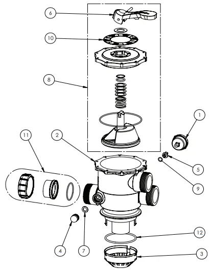
1.5” Valve Replacement Parts
Item# | Part # | Description |
| 1 | 272520 | Handle |
| 2 | 272405 | Screw, Handle |
| 3 | 272505 | Washer, Plastic (2 Req.) |
| 4 | 272599 | Valve Position Label |
| 5 | 272511 | O-Ring, Diverter Shaft |
| 6 | 272535 | Spring, 100lb,1-3/8 O.D. |
| 7 | 354053 | O-Ring Top |
| 8 | 272512 | Diverter w/Gasket |
| 9 | 272530 | Valve Body & Diffuser |
| 10 | 273512 | Air Bleeder w/O-Ring |
| 11 | 152165 | Clamp Asy1 |
| 12 | 152166 | Clamp Half (2 Req.) |
| 13 | 152168 | Clamp Screw (2 Req.) |
| 14 | 152167 | Clamp Nut (2 Req.) |
| 15 | 354541 | Screw #10-24 SS (6 req.) |
| 16 | 272555 | Washer 9/16 SS (6 req.) |
| 17 | 272554 | Nut Serrated SS (6 req.) |
| 18 | 272531 | Valve Top Assembly2 |
| 19 | 190059 | Pressure Gauge |
| 20 | 272550 | Sight Glass |
| 21 | 271106 | Gasket, Sight Glass |
| 22 | 272518 | Diffuser |
| 23 | 272541 | Valve Body O-Ring |
| * | 272517 | Valve Manual |
Note:
(*) Not Shown
(1) Clamp Assembly consists of items 12 thru 14.
(2) Valve Top Assembly consists of items 1 thru 8 and Valve Manual P/N 272517.
2” Valve Replacement Parts
Item# | Part # | Description |
| 1 | 190059 | Pressure Gauge |
| 2 | 270210Z | Valve Body |
| 3 | 272541 | Diffuser |
| 4 | 272556Z | Sight Glass |
| 5 | 272557Z | Drain Plug |
| 6 | 272558Z | Handle |
| 7 | 272567Z | Gasket, Sight Glass |
| 8 | 272568Z | Valve Top Assembly1 |
| 9 | 272573Z | Drain O-Ring |
| 10 | 272576Z | Valve Position Label |
| 11 | 272590Z | Union Kit |
| 12 | 274402Z | Valve Body O-Ring |
Note:
(1) Valve Top Assembly consists of items 6 and 10.
1620 HAWKINS AVE., SANFORD, NC 27330 • (919) 566-8000
10951 WEST LOS ANGELES AVE., MOORPARK, CA 93021 • (805) 553-5000
WWW.PENTAIRPOOL.COM
All Pentair trademarks and logos are owned by Pentair or one of its global affiliates.
Sta-Rite®, Sand Dollar®and Cristal-Flo™ are trademarks and/or registered trademarks of Pentair Water
Pool and Spa, Inc. and/or its affiliated companies in the United States and/ or other countries.
Unless expressly noted, names and brands of third parties that may be used in this document are not used to indicate any affiliation or endorsement between the owners of these names and brands and Pentair Water Pool and Spa, Inc.
Those names and brands may be the trademarks or registered trademarks of those third parties.
Because we are continuously improving our products and services, Pentair reserves the right to change specifications without prior notice.
Pentair is an equal opportunity employer.
© 2017 Pentair Water Pool and Spa, Inc. All rights reserved. This document is subject to change without notice.
 P/N 152006 REV. D 8/18/17
Documents / Resources
 | PENTAIR CRISTAL-FLO II Top Mount Sand Filter [pdf] Installation Guide CRISTAL-FLO II Top Mount Sand Filter, CRISTAL-FLO II, Top Mount Sand Filter |
 | PENTAIR CRISTAL-FLO II Top Mount Sand Filter [pdf] User Guide SAND DOLLAR, CRISTAL-FLO II, Top Mount Sand Filter, CRISTAL-FLO II Top Mount Sand Filter, Mount Sand Filter, Sand Filter, Filter |


