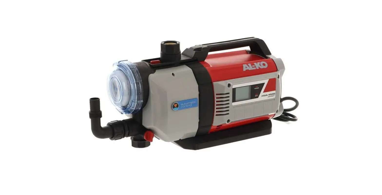
AL-KO HWA 4500 Comfort Home Automatic Water Pump Instruction Manual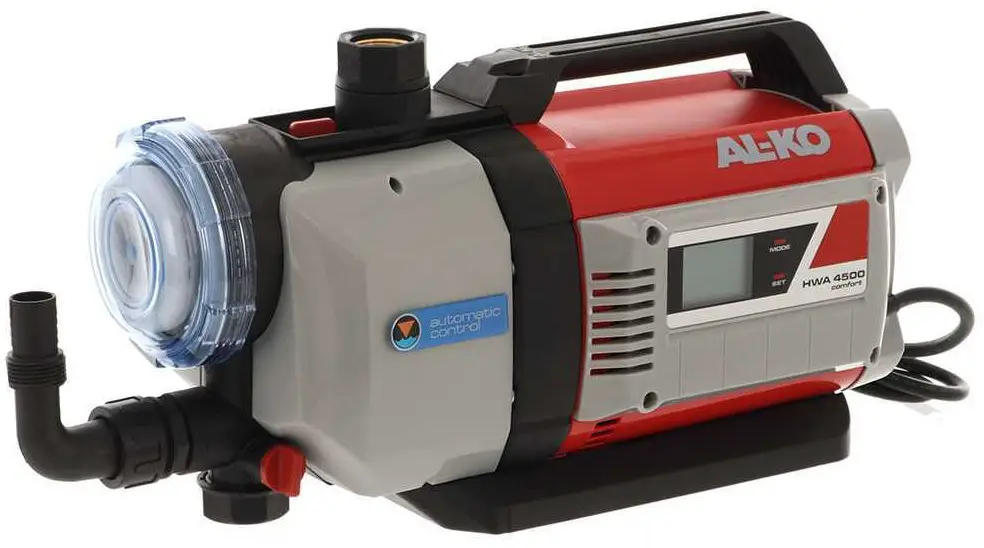
Instructions
 | HWA 4000 comfort (Art.Nr. 113 139) | HWA 4500 comfort (Art.Nr. 113 140) | HWA 6000/5 Premium (Art.Nr. 113 141) |
 | 1000 W | 1300 W | 1400 W |
 | 230 V AC/50 Hz | 230 V AC/50 Hz | 230 V AC/50 Hz |
 | X 4 | X 4 | X 4 |
 | 81 dB (A) | 81 dB (A) | 73 dB (A) |
 | 8 m | 8 m | 8 m |
 | 45 m / 4,5 bar | 50 m / 5,0 bar | 60 m / 6,0 bar |
 | 4000 l/h | 4500 l/h | 6000 l/h |
 | 35 °C | 35 °C | 35 °C |
 | 1″ | 1″ | 1″ |
 | 11 kg | 11,2 kg | 14,1 kg |
 | 1 | 1 | 5 |
ABOUT THIS HANDBOOK
- Read this documentation before starting up the machine. This is a precondition for safe working and flawless operation.
- Observe the safety warnings in this documentation and on the product.
- This documentation is a permanent integral part of the product described and must be passed on to the new owner if the product is sold.
Explanation of symbols
![]() CAUTION!
CAUTION!
Following these safety warnings carefully can prevent personal injury and/or material damage.
![]() Special instructions for greater ease of understanding and improved handling.
Special instructions for greater ease of understanding and improved handling.
PRODUCT DESCRIPTION
This documentation describes various different unit models. Identify your model using the identification plate.
Product overview
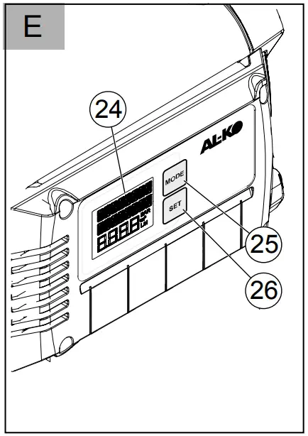
Domestic water pump (Fig. A – E)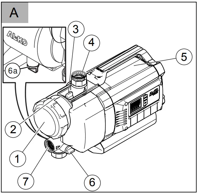
| 1 | Clear filter cover |
| 2 | Pump housing |
| 3 | Filling screw |
| 4 | Pump outlet/pressure line connection |
| 5 | Motor housing |
| 6 | Drain screws |
| 7 | Pump inlet/suction line connection |
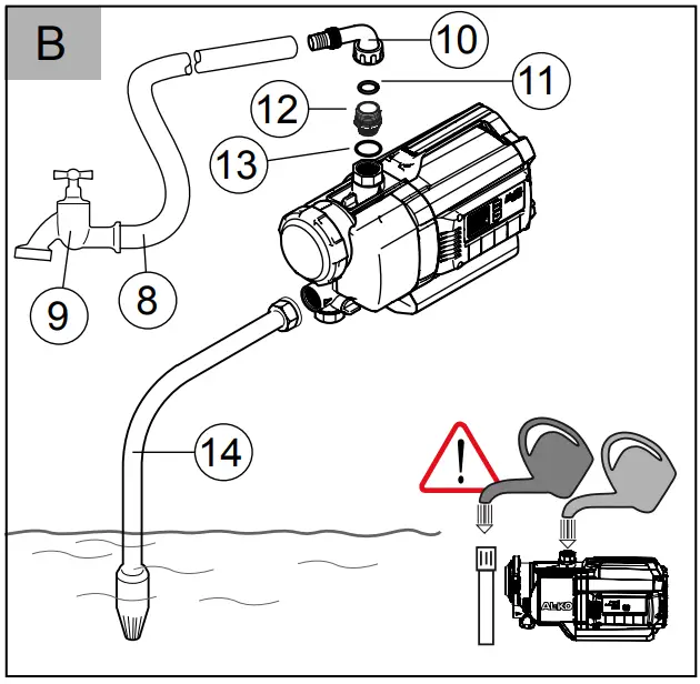
| 8 | Pressure line |
| 9 | Water tap |
| 10 | Elbow nipple |
| 11 | Seal |
| 12 | Connecting nipple |
| 13 | Seal |
| 14 | Suction line |
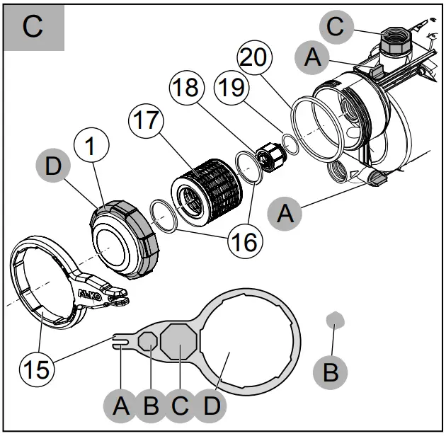
| 15 | Filter spanner |
| 16 | Filter seal |
| 17 | Filter |
| 18 | Check valve |
| 19 | Check valve seal |
| 20 | Housing seal |
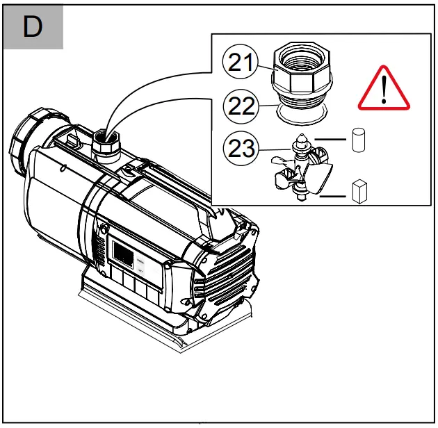
| 21 | Screw-in nipple |
| 22 | Seal |
| 23 | Measuring unit float body |
| 24 | Display |
| 25 | MODE button |
| 26 | SET button |
Designated use
The unit is intended for private use in the house and garden, and is exclusively suited to pumping clean water and rainwater.
It is suitable for:
- Watering the garden and premises
- Water supply in the house
- Pressure increase in the water supply
![]() If the pressure of the water supply is increased, the local regulations must be observed. Your sanitation expert will provide the necessary information.
If the pressure of the water supply is increased, the local regulations must be observed. Your sanitation expert will provide the necessary information.
Possible misuse
The house water system is not suitable for the conveying:
- Water containing sand, salt water and waste water with textile and paper content
- Aggressive, corrosive, explosive or fuming chemicals or liquids
- Fluids above 35°C.
![]() The unit is not allowed to be used for pumping water for use in food or beverages.
The unit is not allowed to be used for pumping water for use in food or beverages.
The unit is not suitable for continuous use.
SCOPE OF DELIVERY
The unit is supplied ready for operation, with key for filter cover, elbow nipple and operating instructions.
Function
The described unit is an automatically working pump. The pump switches itself on and off according to the pressure (see technical data). When a draw-off point is opened, the pump draws in water through the pump inlet (7) and pumps it through the pressure line connection (4) to the draw-off point.
The pump switches itself off automatically about 20 seconds after the draw-off point is closed.
Thermal protection
The unit is fitted with a thermal protection switch which switches the motor off in the event of overheating. The pump switches on again automatically after a cooling down period of approx. 15 – 20 minutes.
Dry-run protection
The unit is provided with dry-run protection. The dry-run protection switches the pump off after about 90 seconds if water is not being drawn up or if the suction line is damaged.
Pressure sensor
The unit is provided with a pressure sensor. This sensor automatically switches the pump off and on.
Display indicator
For displaying the operational conditions and fault messages, the unit is equipped with a display (Fig. E -24). With the MODE button (E -25) you can select various different settings and displays and confirm with the SET button (-26).
SAFETY INSTRUCTIONS
![]() CAUTION!
CAUTION!
Risk of injury!
Use the machine and the extension cable only in perfect working order. Damaged equipment may not be operated.
Do not disable safety and protective devices!
- Children, or people who are not familiar with the operating instructions, are not allowed to use the machine.
- Never lift, transport or suspend the unit using the connection cable.
- Unilateral modifications or conversions of the unit are prohibited.
Electrical safety
![]() CAUTION!
CAUTION!
Danger when touching voltage conducting parts!
Disconnect the plug from the mains if the extension cable is damaged or severed!
We recommend connecting a RCD (residual current operated device) having a nominal residual current of < 30 mA.
- The pump may not be operated while people are in the pool or pond.
- The house mains voltage must agree with the details quoted in the technical data, do not use any other supply voltage.
- The unit must only be operated with an electrical installation in accordance with DIN/VDE 0100, Part 737, 738 and 702. Protection must be provided by a 10 A line protection switch and a RCCD (residual current operated device) having a nominal residual current of 10/30 mA.
- Use only extension cables that are suitable for use outdoors – minimum cross-section 1.5 mm2. Cable drums should always be unrolled completely.
- Damaged or brittle extension cables must not be used.
- Check the condition of your extension cable each time you start to use the equipment.
ASSEMBLY
![]() CAUTION!
CAUTION!
The unit will not function correctly if the draw-off point is 15 m higher than the unit.
Erect the unit
- Prepare a flat solid area for erection.
- Erect the unit horizontally and where it will not be flooded.
- The unit must be protected from the rain and direct water jet impingement.
![]() In day-to-day operation (automatic mode) you must take measures to exclude the possibility that flooding of the room occurs as a result of malfunctions on the unit.
In day-to-day operation (automatic mode) you must take measures to exclude the possibility that flooding of the room occurs as a result of malfunctions on the unit.
Connect the suction line
- Select the length of the suction line (Fig. B-14) so that the house water system cannot run dry. The suction line must always be at least 30 cm under the surface of the water.
- Connect the suction line. Make sure that the connection does not leak, without damaging the thread.
- We recommend using flexible hoses at the pump inlet (Fig. A -10). This prevents mechanical tension or pressure from being exerted on the house water system.
- Always lay the suction line with an uphill gradient.
![]() If the suction height is more than 4 m, you must use a suction hose having a diameter greater than 1″. We recommend the use of an AL-KO suction unit with suction hose, suction filter and flow-back stop. Ask your expert dealer.
If the suction height is more than 4 m, you must use a suction hose having a diameter greater than 1″. We recommend the use of an AL-KO suction unit with suction hose, suction filter and flow-back stop. Ask your expert dealer.
Fitting the pressure line
- Screw the connecting nipple (Fig. B -12) with the round seal ring (Fig. B -13) into the pump outlet (Fig. A -4).
- Screw the elbow nipple (Fig. B -10) with seal (Fig. B -11) onto the connecting nipple (Fig. B-12) and turn the elbow nipple in the desired direction.
- Fix a pressure line (Fig. B -8) onto the elbow nipple (Fig. B -10).
STARTUP
![]() On initial commissioning the display (Fig. E -24) shows all information in English.
On initial commissioning the display (Fig. E -24) shows all information in English.
Select the desired language with the MODE button (-25) and confirm with the SET button (-26).
Filling the unit
![]() CAUTION!
CAUTION!
Dry running will destroy the pump! The pump must be filled with water up to the overflow before each use so that it can draw water immediately.
- Open the filling screw (Fig. A -3) with the filter key.
- Fill with water via the filling screw until the marl on the pump housing is reached.
- Screw the filling screw back in position.
In order to reduce the suction time, fill the suction hose with water before screwing in position.
Initial start-up of the unit
- Open a closing-off device (valve, spray nozzle, water tap) in the pressure line.
- Insert the mains plug on the connection cable into the plug socket.
- The pumps starts to pump.
- When no more air comes out with the water, close the closing off device in the pressure line.
- The pump switches off when the flow stops, after building up pressure.
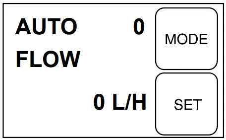
- The domestic water pump is ready for operation. The display shows AUTO O and FLOW O.
Operation
- Take the unit into operation as described (initial start-up of the unit).
- The domestic water pump is electronically controlled and operates fully automatically after initial start-up.
- The pump switches on when water is drawn off at the pressure side. The display shows ON X and PRESSURE as well as the actual pressure.
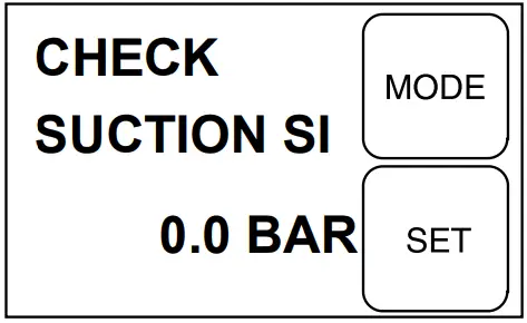
![]() If no water has been drawn in through the suction line within 20 seconds, the pump switches to a checking mode. In this, the pump continues to run and the display shows CHECK SUCTION SIDE.
If no water has been drawn in through the suction line within 20 seconds, the pump switches to a checking mode. In this, the pump continues to run and the display shows CHECK SUCTION SIDE.
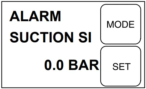
![]() If no water is drawn in via the suction line (Fig. B -14) in approx. 90 seconds, the dry-run protection switches off the pump, and the display shows ALARM and SUCTION SIDE.
If no water is drawn in via the suction line (Fig. B -14) in approx. 90 seconds, the dry-run protection switches off the pump, and the display shows ALARM and SUCTION SIDE.
Troubleshooting and fault rectification, see Help in case of malfunctions.
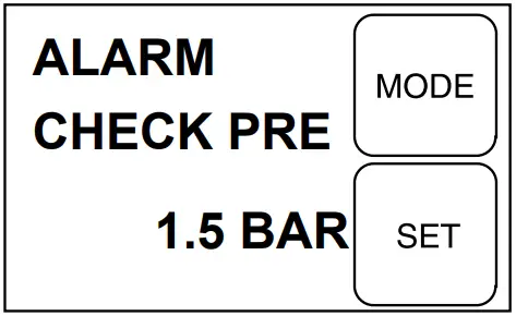
![]() If the pump switches on and off frequently although no water is being drawn off, the pump will switch itself off to protect against overheating and the display shows ALARM and PRESSURE SIDE. Troubleshooting and fault rectification, see Help in case of malfunctions.
If the pump switches on and off frequently although no water is being drawn off, the pump will switch itself off to protect against overheating and the display shows ALARM and PRESSURE SIDE. Troubleshooting and fault rectification, see Help in case of malfunctions.
Switching the pump off
- Remove the mains plug from the plug socket.
- Close the closing off devices (valves, spray nozzles, water tap) in the pressure line.
![]() CAUTION!
CAUTION!
Danger of injury from hot water
In extended use against the closed pressure side (>10 min.), the water in the pump can be severely heated up and can be emitted in an uncontrolled manner!
Isolate the unit from the mains and allow the pump and water to cool down. Start the unit again only after all the faults have been rectified!
The risk of injury from hot water can arise if:
- the installation is not correct
- the pressure side is closed off
- there is a lack of water in the suction line, or if
- the pressure switch is defective.
Procedure
- Isolate the unit from the mains and allow the pump and water to cool down.
- Check the unit, the installation and water level.
- Start the unit again only after all the faults have been rectified!
MAINTENANCE AND CARE
![]() CAUTION!
CAUTION!
The pump must be isolated from the mains before any maintenance and service work. Remove the mains plug from the plug socket.
Flushing the pump
After conveying swimming pool water containing chlorine or fluids that leave a residue the pump must be flushed out with clear water.
Cleaning the filter
- Unscrew the drain screw filter chamber (Fig. A -6) of the draining opening, drain the filter chamber and close the draining opening again.
- Clear filter cover (Fig. A -1) using the filter key (Fig. C -15/D) .
- Remove the filter (Fig. C -16/C-17) from the filter housing (Fig. A -2) and clean under flowing water.
- Cleaning the filter housing and clear sight filter cover.
- Before fitting the filter, check the filter seal (Fig. C -16) and the housing seal (Fig. C -20) for damage, and replace if necessary.
- Fit the filter, screw the filter clear sight cover in place and tighten hand-tight with the filter key.
Cleaning the check valve
- Removing and fitting the filter (see Section “Cleaning the Filter”).
- Check valve (Fig. C -18) and clean under flowing water.
- Replace seal (Fig. C -19) if necessary.
- Fit check valve.
Unscrew float body
- Pressure line (Fig. B -8) with elbow nipple (Fig. B -10) and connecting nipple (Fig. B -12) must be unscrewed.
- Unscrew screw-in nipple (Fig. D -21) with seal (Fig. D -22) . Note the fitting position of the float body (Fig. D -23) . Pull out the float body and clean it.
- Replace the float body – note fitting position (Fig. D).
Remove blockages
- Isolate the unit from the mains and secure against switching on again.
- Remove the suction hose from pump inlet.
- Connect the pressure hose to the water supply.
- Allow water to run through the pump housing until the blockage is removed.
- Check that the pump is running freely by switching it on briefly.
- Start the house water system again as described.
STORAGE
- If there is a risk of frost, the entire system must be drained (pump, lines, storage vessel and filter chamber).
- Drain the suction line (Fig. B -14) and the pressure line (Fig. B -8).
- Unscrew the drain screws (Fig. A -6/A-6a) and allow the water to flow out of the pump.
- Screw the drain screws (Fig. A -6/A-6a) back in position and store the pump, lines and storage vessel in a frost-free environment.
DISPLAY INDICATIONS
- On initial commissioning, all information appears on the display in English.
- All functions can be called up using the MODE button. The displays/functions called up are confirmed with the SET button.
![]() The information in the second line of the display is partially shown as running text which provides running information continuously.
The information in the second line of the display is partially shown as running text which provides running information continuously.
Normal operation and additional functions
| Setting the language | ||
| Display indicator | Switching condition | Function / actions |
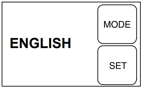 | Pump running or switched off | Press the MODE button for longer than 3 se- conds, the operating language is activated. Change the operating language by pressing the MODE button (30). Confirm the new operating language by pressing the SET button. |
| Initial start-up of the unit | ||
| Display indicator | Switching condition | Function / actions |
 | Pump ready | Pump starts automatically when water is drawn off. |
| Pump runs in normal operation | ||
| Display indicator | Switching condition | Function / actions |
| Pump runs in normal operation | ||
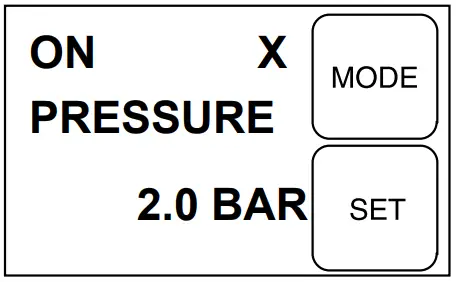 | Pump is switched on and is pumping water.
| |
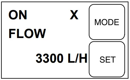 | Pump is switched on and is pumping water.
| |
| Rotating X after ON symbolises pump is ON | ||
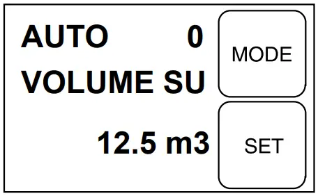
| Pump in automatic mode, not pumping | ||
| Display indicator | Switching condition | Function / actions |
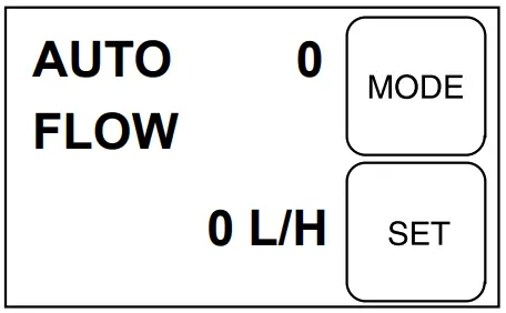 | Pump is switched on but is not pumping water.
| Pump starts automatically when pressure line is opened (valves, spray nozzles, water tap, etc.). |
 | Pump is switched on but is not pumping water.
| Pump starts automatically when pressure line is opened (valves, spray nozzles, water tap, etc.). |
| 0 after AUTO symbolises pump off | ||
| Displaying flow rates | ||
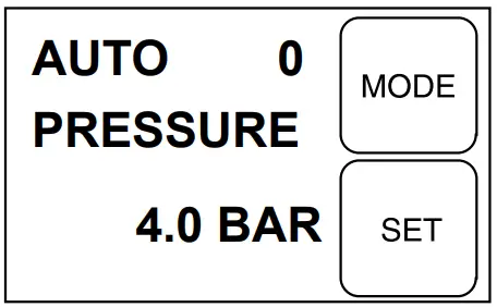
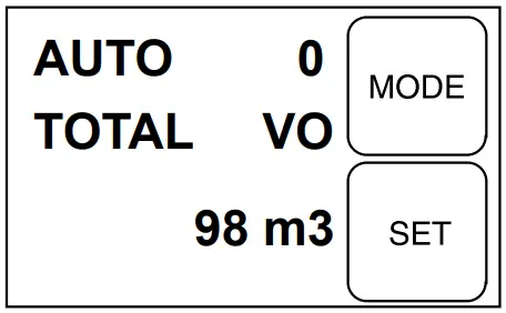
| The following information can be displayed by pressing the MODE key both during operation (ON) and in AUTO status. | ||
| Display indicator | Switching condition | Function / actions |
 |
| |
 |
| Press the SET button to reset to zero. |
| Press the MODE button to switch between displaying the pressure and through-flow as well as flow rate. | ||
TROUBLESHOOTING
![]() CAUTION!
CAUTION!
Disconnect the mains plug before any fault rectification work. Faults in the electrical system must be rectified by a qualified electrician.
| Malfunction | Cause | Rectification |
| Pump drive motor does not run. | No mains power. | Check fuses and power supply. |
 | Pressure and through-flow are deviating from normal values, but pump is still run- ning. | Message appears after 20 s. Pump at- tempts to rectify fault itself for 90 s. No action required. If fault persists after 90 s, pump switches off as dry-run protection. |
 | Pump is switched off as dry- run protection. | Fault on suction side. Rectify fault and press SET. Pump then starts up again. Attention: hot water when restart occurs. |
| Leak on suction side. | Check suction valve and suction hose. | |
| Leak on filter bowl. | Check filter bowl seal, retighten filter bowl. | |
| Leak on filter chamber drain screw. | Check drain screw seal, retighten drain screw. | |
| End of hose not in water, water reservoir (e.g. cistern or borehole) empty. Pump drawing in air. | Suction line must always be at least 30 cm under the surface of the water. | |
| Filter heavily contaminated. | Clean filter. | |
| Suction line blockage | Remove dirt from the suction area. | |
| Flow rate less than 300 l/h. | Increase flow rate. | |
 | Pump switches on and off several times although no water is being drawn off.
| Fault on pressure side, e.g. leak. Even small leaks on water taps and toilets can cause the system pressure to drop. Check the pressure line and draw-off points for leaks. Check and clean the check valve (18) in the filter chamber. Rectify the fault and confirm with SET – pump then restarts. Attention: hot water when restart occurs! |
![]() If the faults cannot be rectified, please contact our customer service department.
If the faults cannot be rectified, please contact our customer service department.
DISPOSAL
 Do not dispose of worn-out machines or spent batteries (including rechargeable batteries) in domestic waste!
The packaging, machine and accessories are made from recyclable materials and must be disposed of accordingly.
WARRANTY
We will address claims for any defects in materials and workmanship during the statutory period of limitation by means of repairs or replacements of our choice. The period of limitation is governed by the laws of the country in which the machine was purchased.
Our warranty applies only if:
- The machine has been properly handled
- The operating instructions have been adhered to
- Original replacement parts have been used
The warranty is no longer in effect if:
- Efforts have been made to repair the machine
- Technical modifications have been made to the machine
- The machine has not been used for its intended purpose
The warranty does not cover:
- Damage to paint work through normal use
- Parts subject to wear as indicated in the replacement parts list with a box [xxx xxx (x)]
- Internal combustion engines – separate warranty conditions of the respective engine manufacturer apply
The warranty period begins with the purchase by the first buyer. The warranty period begins on the date that appears on the original purchase receipt. In the event of a warranty claim, please your contact supplier or the nearest authorised customer service centre with this warranty declaration and the purchase receipt in hand. This warranty does not affect the legal warranty claims by the purchaser against the seller.
EU DECLARATION OF CONFORMITY
We hereby declare that this product in the version introduced into trade by us, complies with the requirements of the harmonised EU Directives, EU safety standards and the product-specific standards.
Product
Domestic water system
Serial number
G3043045
Type
HWA 4000 comfort
HWA 4500 comfort
HWA 6000/5 Premium
Manufacturer
AL-KO Geräte GmbH
Ichenhauser Str. 14
D-89359 Kötz
Duly authorised person
Andreas Hedrich
Ichenhauser Str. 14
D-89359 Kötz
EU Directives
2014/35/EU
2014/30/EU
2000/14/EU (13)
2011/65/EU
Harmonised standards
EN 60335-1:2012
EN 60335-2-41:2012
EN 62233:2008
EN 55014-1:2012
EN 55014-2:2016
EN 61000-3-2:2014
EN 61000-3-3:2014
Kötz, 19.01.2016
Wolfgang Hergeth
Managing Director
Sound pressure level
EN ISO 3744
HWA 4000 comfort
measured: 80 dB(A)
guaranteed: 82 dB(A)
HWA 4500 comfort
measured: 81 dB(A)
guaranteed: 83 dB(A)
HWA 6000/5 Premium
measured: 73 dB(A)
guaranteed: 75 dB(A)
Conformity evaluation
2000/14/EC Appendix V
![]()
2015
Spare parts
HWA 4000 / HWA 4500
Art.Nr. 113 139 / 113140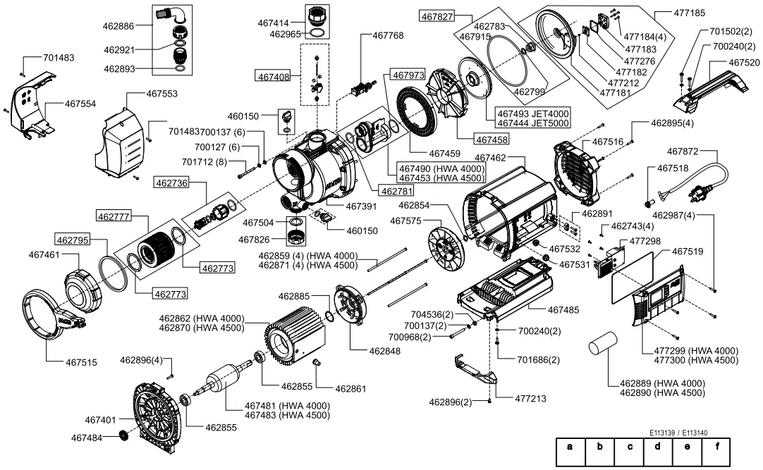
HWA 6000/5
Art.Nr. 113 141_1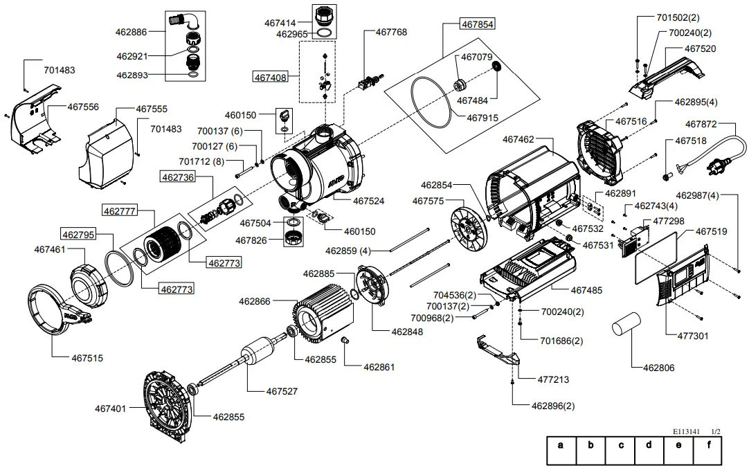
HWA 6000/5
Art.Nr. 113 141_2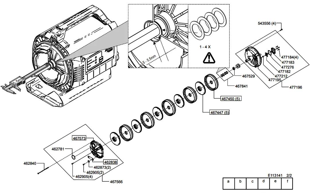
Customer service
| Country | Company | Telephone | Fax |
| A | AL-KO KOBER Ges.m.b.H. | (+43)3578/2515-100 | (+43)3578/2515-31 |
| AUS | AL-KO INTERNATIONAL Pty. Ltd. | (+61)3/9767-3700 | (+61)3/9767-3799 |
| B / L | Eurogarden NV | (+32)16/805427 | (+32)16/805425 |
| BG | Valerii S&M Group SJ | (+359)2 942 34 02 | (+359)2 942 34 10 |
| CH | AL-KO KOBER AG | (+41)56/418-31 53 | (+41)56/4183160 |
| CZ | AL-KO KOBER Spol. S.R.O. | (+420)382/210381 | (+420)382/212782 |
| D | AL-KO GERATE GmbH | (+49)8221/203-0 | (+49)8221/97-8199 |
| DK | AL-KO GINGE NS | (+45)98 8210 00 | (+45)98 8254 54 |
| EST/LT/LV | SIA AL-KO KOBER | (+371)67/627-326 | ((+371)67/807-018 |
| F | AL-KO S.A.S. | (+33)3/8576-3500 | (+33)3/8576-3581 |
| GB | Rochford Garden Machinery Ltd. | (+44)1963/828050 | (+44)1963/828052 |
| H | AL-KO KFT | (+36)29/53 70 -50 | (+36)29/5370-51 |
| HR | Brun.ko.-prom d.o.o. | (+385)1 3096 567 | (+385)1 3096 567 |
| N | AL-KO KOBER GmbH / SRL | (+39) 0 39/ 932 9-311 | (+39) 039/9 32 9-390 |
| IN | AGRO-COMMERCIAL | (+91)3322874206 | (+91)3322874139 |
| IQ | Avro Gulistan Com | (+946)750 450 80 64 | |
| IRL | Cyril Johnston & Co. Ltd. | (+44)2890813121 | (+44)2890914220 |
| LY | ASHOFAN FOR AGRICULT. ACC. | (+218)512660209 | (+218)512660209 |
| MA | BADRA Sarl | (+212)022447128 | (+212)022447130 |
| MK | Techno Geneks | (+389)2 2551801 | (+389)2 2520175 |
| N | AL-KO GINGE NS | (+47)64/86-2550 | (+47)64/86-2554 |
| NL | 0.DE LEEUW GROENTECHNIEK | (+31)38/444 6160 | (+31)38/444 6358 |
| PL | AL-KO KOBER Sp. z.o.o. | (+48)61/816-1925 | (+48)61/816-1980 |
| R 0 | SC PECEF TEHNICA SRL | (+40)344 40 30 30 | (+40)244 51 44 86 |
| RUS | 000 AL-KO KOBER | (+7)499/16708-42 | (+7)499/96600-00 |
| RUS | ZAO AL-KO St. Petersburg GmbH | (+7)812/446-1084 | (+7)812/446-1084 |
| S | GINGE Svenska AB | (+46)31/57-3580 | (+46)31/57-5620 |
| SK | AL-KO KOBER Slovakia Spol. S.R.O. | (+421)2/4564-8267 | (+421)2/4564-8117 |
| SLO | Darko Opara s.p. | (+386)1 722 58 50 | (+386)1 722 58 51 |
| SR B | Agromarket d.o.o. | (+381)34 308 000 | (+381)34 308 16 |
| TR | ZIMAS A.S. | (+90)232 4580586 | (+90)232 4572697 |
| UA | TOV AL-KO KOBER | (+380)44/392-07-08 | (+380)44/392-07-09 |
AL-KO GERATE GmbH | Head Quarter I Ichenhauser St r. 14 | 89359 Utz | Deutschland Telefon: (+49)8221/203-0 | Telefax: (+49)8221/97-8199 | www.al-ko.com